EP1180974B1 - Verfahren für ultraschallbilddarstellung und ultraschalldiagnostisches gerät - Google Patents
Verfahren für ultraschallbilddarstellung und ultraschalldiagnostisches gerät Download PDFInfo
- Publication number
- EP1180974B1 EP1180974B1 EP01912972A EP01912972A EP1180974B1 EP 1180974 B1 EP1180974 B1 EP 1180974B1 EP 01912972 A EP01912972 A EP 01912972A EP 01912972 A EP01912972 A EP 01912972A EP 1180974 B1 EP1180974 B1 EP 1180974B1
- Authority
- EP
- European Patent Office
- Prior art keywords
- strength
- ultrasonic
- contrast agent
- transmission
- ultrasonic wave
- Prior art date
- Legal status (The legal status is an assumption and is not a legal conclusion. Google has not performed a legal analysis and makes no representation as to the accuracy of the status listed.)
- Expired - Lifetime
Links
- 238000003384 imaging method Methods 0.000 title claims description 21
- 238000000034 method Methods 0.000 title claims description 9
- 230000005540 biological transmission Effects 0.000 claims abstract description 62
- 239000002872 contrast media Substances 0.000 claims abstract description 61
- 239000000523 sample Substances 0.000 claims description 5
- 230000017531 blood circulation Effects 0.000 abstract description 10
- 238000010586 diagram Methods 0.000 description 23
- 239000006185 dispersion Substances 0.000 description 23
- 239000011800 void material Substances 0.000 description 7
- 230000015572 biosynthetic process Effects 0.000 description 6
- 238000002604 ultrasonography Methods 0.000 description 4
- 206010016322 Feeling abnormal Diseases 0.000 description 2
- 239000008280 blood Substances 0.000 description 1
- 210000004369 blood Anatomy 0.000 description 1
- 210000004204 blood vessel Anatomy 0.000 description 1
- 230000001419 dependent effect Effects 0.000 description 1
- 238000002592 echocardiography Methods 0.000 description 1
- 210000002837 heart atrium Anatomy 0.000 description 1
- 210000001308 heart ventricle Anatomy 0.000 description 1
Images


Classifications
-
- A—HUMAN NECESSITIES
- A61—MEDICAL OR VETERINARY SCIENCE; HYGIENE
- A61B—DIAGNOSIS; SURGERY; IDENTIFICATION
- A61B8/00—Diagnosis using ultrasonic, sonic or infrasonic waves
- A61B8/48—Diagnostic techniques
- A61B8/481—Diagnostic techniques involving the use of contrast agents, e.g. microbubbles introduced into the bloodstream
-
- A—HUMAN NECESSITIES
- A61—MEDICAL OR VETERINARY SCIENCE; HYGIENE
- A61B—DIAGNOSIS; SURGERY; IDENTIFICATION
- A61B8/00—Diagnosis using ultrasonic, sonic or infrasonic waves
- A61B8/06—Measuring blood flow
-
- G—PHYSICS
- G01—MEASURING; TESTING
- G01S—RADIO DIRECTION-FINDING; RADIO NAVIGATION; DETERMINING DISTANCE OR VELOCITY BY USE OF RADIO WAVES; LOCATING OR PRESENCE-DETECTING BY USE OF THE REFLECTION OR RERADIATION OF RADIO WAVES; ANALOGOUS ARRANGEMENTS USING OTHER WAVES
- G01S7/00—Details of systems according to groups G01S13/00, G01S15/00, G01S17/00
- G01S7/52—Details of systems according to groups G01S13/00, G01S15/00, G01S17/00 of systems according to group G01S15/00
- G01S7/52017—Details of systems according to groups G01S13/00, G01S15/00, G01S17/00 of systems according to group G01S15/00 particularly adapted to short-range imaging
- G01S7/52023—Details of receivers
- G01S7/52036—Details of receivers using analysis of echo signal for target characterisation
- G01S7/52038—Details of receivers using analysis of echo signal for target characterisation involving non-linear properties of the propagation medium or of the reflective target
- G01S7/52041—Details of receivers using analysis of echo signal for target characterisation involving non-linear properties of the propagation medium or of the reflective target detecting modification of a contrast enhancer, e.g. detecting the destruction of a contrast agent by an acoustic wave, e.g. loss of correlation
-
- G—PHYSICS
- G01—MEASURING; TESTING
- G01S—RADIO DIRECTION-FINDING; RADIO NAVIGATION; DETERMINING DISTANCE OR VELOCITY BY USE OF RADIO WAVES; LOCATING OR PRESENCE-DETECTING BY USE OF THE REFLECTION OR RERADIATION OF RADIO WAVES; ANALOGOUS ARRANGEMENTS USING OTHER WAVES
- G01S7/00—Details of systems according to groups G01S13/00, G01S15/00, G01S17/00
- G01S7/52—Details of systems according to groups G01S13/00, G01S15/00, G01S17/00 of systems according to group G01S15/00
- G01S7/52017—Details of systems according to groups G01S13/00, G01S15/00, G01S17/00 of systems according to group G01S15/00 particularly adapted to short-range imaging
- G01S7/52053—Display arrangements
- G01S7/52057—Cathode ray tube displays
- G01S7/5206—Two-dimensional coordinated display of distance and direction; B-scan display
- G01S7/52066—Time-position or time-motion displays
-
- G—PHYSICS
- G01—MEASURING; TESTING
- G01S—RADIO DIRECTION-FINDING; RADIO NAVIGATION; DETERMINING DISTANCE OR VELOCITY BY USE OF RADIO WAVES; LOCATING OR PRESENCE-DETECTING BY USE OF THE REFLECTION OR RERADIATION OF RADIO WAVES; ANALOGOUS ARRANGEMENTS USING OTHER WAVES
- G01S7/00—Details of systems according to groups G01S13/00, G01S15/00, G01S17/00
- G01S7/52—Details of systems according to groups G01S13/00, G01S15/00, G01S17/00 of systems according to group G01S15/00
- G01S7/52017—Details of systems according to groups G01S13/00, G01S15/00, G01S17/00 of systems according to group G01S15/00 particularly adapted to short-range imaging
- G01S7/52053—Display arrangements
- G01S7/52057—Cathode ray tube displays
- G01S7/52073—Production of cursor lines, markers or indicia by electronic means
-
- G—PHYSICS
- G01—MEASURING; TESTING
- G01S—RADIO DIRECTION-FINDING; RADIO NAVIGATION; DETERMINING DISTANCE OR VELOCITY BY USE OF RADIO WAVES; LOCATING OR PRESENCE-DETECTING BY USE OF THE REFLECTION OR RERADIATION OF RADIO WAVES; ANALOGOUS ARRANGEMENTS USING OTHER WAVES
- G01S15/00—Systems using the reflection or reradiation of acoustic waves, e.g. sonar systems
- G01S15/88—Sonar systems specially adapted for specific applications
- G01S15/89—Sonar systems specially adapted for specific applications for mapping or imaging
- G01S15/8906—Short-range imaging systems; Acoustic microscope systems using pulse-echo techniques
- G01S15/8979—Combined Doppler and pulse-echo imaging systems
Definitions
- the present invention relates to a method of ultrasonic imaging and an ultrasonic diagnostic apparatus, and more particularly to a method of ultrasonic imaging and an ultrasonic diagnostic apparatus capable of producing ultrasonic images by which it is possible to visually recognize at a glance the time-wise change of a blood flow.
- images are formed of frames in which some beams have higher ultrasound power for dispersing the contrast agent and some beams have lower ultrasound power for not dispersing the contrast agent.
- image frames are formed in which all the beams of a frame have higher ultrasound power interposed with frames in which all the beams have lower ultrasound power.
- imaging for a high-transmission frame a frame taken by use of an ultrasonic wave which is strong enough to disperse the contrast agent
- imaging for low-transmission frames frames taken by use of an ultrasonic wave which is not so strong as to disperse the contrast agent
- imaging for another high-transmission frame is carried out on expiration of the time at which the view field is filled with a blood flow including the contrast agent, with these operations being implemented cyclically, as shown in FIG. 1.
- vertical line segments aligning along the time axis represent transmission time points and transmission strengths of sonic beams which form the frames.
- Fig. 2(a) shows sonic beams which form a high-transmission frame, and the bold lines signify an ultrasonic wave which is strong enough to disperse the contrast agent.
- V is a blood vessel, and the arrow indicates the direction of blood flow.
- Fig. 2(b) shows sonic beams which form a low-transmission frame, and the thin lines signify an ultrasonic wave which is not so strong as to disperse the contrast agent.
- ultrasonic imaging method and ultrasonic diagnostic apparatus of this invention which actively utilize the dispersion of contrast agent in the presence of a strong ultrasonic wave, it is possible to produce ultrasonic images which enable to visually recognize at a glance the time-wise change of a blood flow.
- Fig. 3 is a block diagram of an ultrasonic diagnostic apparatus 100 based on an embodiment of this invention.
- This ultrasonic diagnostic apparatus 100 is made up of an ultrasonic probe 1, a transmitter/receiver 2 which transmits an ultrasonic wave at a specified transmission strength, receives the echo of ultrasonic transmission, and produces a reception signal, a transmission strength controller 3 which specifies the transmission strength, an operation console 4 which is used by the operator to instruct the transmission strength controller 3, a data processor 5 which produces an ultrasonic image such as a B-mode image from the reception signal, a DSC (digital scan converter) 6 which converts the ultrasonic image into a display image, and a CRT 7 which displays the display image.
- an ultrasonic probe 1 a transmitter/receiver 2 which transmits an ultrasonic wave at a specified transmission strength, receives the echo of ultrasonic transmission, and produces a reception signal
- a transmission strength controller 3 which specifies the transmission strength
- an operation console 4 which is used by the operator to instruct the transmission strength controller 3
- a data processor 5 which produces an ultrasonic image such as a B-mode image from
- Fig. 4(a) is an explanatory diagram of a marking frame produced by the ultrasonic diagnostic apparatus 100.
- the marking frame is defined to be an image of a frame which is produced by the transmission of an ultrasonic wave at the strength for the dispersion of contrast agent for part (shown by the bold lines) of a number of sonic beams which form one frame and the transmission of an ultrasonic wave at the strength for no dispersion of contrast agent for other sonic beams (shown by the thin lines), and the formation of an image for one frame from received signals which correspond to the ultrasonic wave transmission.
- Fig. 4(b) is an explanatory diagram of a no-marking frame produced by the ultrasonic diagnostic apparatus 100.
- the no-marking frame is defined to be an image of a frame which is produced by the transmission of an ultrasonic wave at the strength for the dispersion of contrast agent for all of a number of sonic beams which form one frame, and the formation of an image for one frame from received signals which correspond to the ultrasonic wave transmission.
- Fig. 5 is an explanatory diagram showing the transmission time points and transmission strengths of sonic beams of the ultrasonic diagnostic apparatus 100.
- Vertical line segments aligning along the time axis represent transmission time points and transmission strengths of sonic beams which form the frames.
- imaging for a marking frame Following the imaging for a marking frame, imaging for no-marking frames is carried out continuously, and imaging for another marking frame is carried out after such a time length that the flow range is present within the view field, with these operations being repeated.
- the time difference based on the heart beat may be a multiple of the period of heart beat measured with an electrocardiograph, or may be a multiple of an approximate heart beat period (e.g., 1 second).
- Fig. 6 is a set of explanatory diagrams of images produced by the ultrasonic diagnostic apparatus 100.
- Shown by (a) is a first marking frame, in which case the contrast agent on the sonic beam (bold dashed line) at the transmission strength for the dispersion of contrast agent disperses, whereas the contrast agent on the sonic beams (thin dashed line) at the transmission strength for no dispersion of contrast agent does not disperse.
- (c) Shown by (c) is a second marking frame, in which case only the contrast agent on the sonic beam (bold dashed line) at the transmission strength for the dispersion of contrast agent disperses, as in the case of (a).
- the portion (bold line) where the contrast agent has dispersed in the first marking frame seems to be the black void.
- Shown by (d) is an image after the fifth or later marking frame, in which the portions (bold line) where the contrast agent has dispersed in the preceding marking frames seem to be stripes of the black void.
- the ultrasonic diagnostic apparatus 100 of the foregoing embodiment presents a stripe pattern appended to a flow which intersects the direction of sonic beams as shown by (d) in Fig. 6, whereby it becomes possible to visually recognize the time-wise change at a glance.
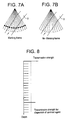
- Fig. 7(a) is an explanatory diagram of a marking frame produced by the ultrasonic diagnostic apparatus.
- the marking frame is defined to be a frame produced by the concentrated transmission of an ultrasonic wave at the strength for the dispersion of contrast agent for a certain depth (indicated by black dots) of a number of sonic beams (thin lines) which form one frame and the transmission of an ultrasonic wave at the strength for no dispersion of contrast agent for other depths, and the formation of an image for one frame from received signals which correspond to the ultrasonic wave transmission.
- a certain depth on sonic beams may be replaced with a certain depth seen from the ultrasonic probe.
- Fig. 7(b) is an explanatory diagram of a no-marking frame.
- the no-marking frame is defined to be a frame which is produced by the transmission of an ultrasonic wave at the strength for no dispersion of contrast agent for all of a number of sonic beams which form one frame, and the formation of an image for one frame from received signals which correspond to the ultrasonic wave transmission.
- Fig. 8 is an explanatory diagram showing the depths and transmission strengths of sonic beams used for the marking frame.
- Lateral line segments aligning on the depth axis represent transmission strengths.
- imaging for no-marking frames is carried out continuously, and imaging for another marking frame is carried out after such a time length that the flow range is present within the view field, with these operations being repeated.
- the time difference based on the heart beat may be a multiple of the period of heart beat measured with an electrocardiograph, or may be a multiple of an approximate heart beat period (e.g., 1 second).
- Fig. 9 is a set of explanatory diagrams of images produced by the ultrasonic diagnostic apparatus.
- Shown by (a) is a first marking frame, in which case the contrast agent in a portion of the depth (white dots) where the contrast agent is to be dispersed disperses, whereas the contrast agent in other portion does not disperse.
- Thin dashed lines represent sonic beams at the transmission strength for no dispersion of contrast agent.
- Shown by (b) is a no-marking frame which follows the first marking frame, in which case the portion (black dots) where the contrast agent has dispersed in the first marking frame has weaker echoes than other portion and seems to be the black void.
- (c) Shown by (c) is a second marking frame, in which case only the contrast agent at the depth (white dots) for the dispersion of contrast agent disperses, as in the case of (a).
- the portion (black dots) where the contrast agent has dispersed in the first marking frame seems to be the black void.
- Shown by (d) is an image after the fourth or later marking frame, in which the portions (black dots) where the contrast agent has dispersed in the preceding marking frames seem to be stripes of the black void.
- the ultrasonic diagnostic apparatus of the foregoing presents a stripe pattern appended to a flow which is virtually parallel to the direction of sonic beams as shown by (d) in Fig. 9, whereby it becomes possible to visually recognize the time-wise change at a glance.
- Fig. 10(a) is an explanatory diagram of a marking frame produced by the ultrasonic diagnostic apparatus.
- the marking frame is defined to be a frame produced by the transmission of an ultrasonic wave at the strength for the dispersion of contrast agent for two or more spaced-out sonic beams (bold lines) among a number of sonic beams which form one frame and the transmission of an ultrasonic wave for other sonic beams at the strength for the dispersion of contrast agent for two or more spaced-out positions of a certain depth (black dots) and at the strength for no dispersion of contrast agent for other depths, and the formation of an image for one frame from received signals which correspond to the ultrasonic transmission.
- a certain depth on sonic beams may be replaced with a certain depth seen from the ultrasonic probe.
- Fig. 10 (b) is an explanatory diagram of a no-marking frame.
- the no-marking frame is defined to be a frame which is produced by the transmission of an ultrasonic wave at the strength for no dispersion of contrast agent for all of a number of sonic beams which form one frame, and the formation of an image for one frame from received signals which correspond to the ultrasonic wave transmission.
- imaging for no-marking frames is carried out continuously, and imaging for another marking frame is carried out after such a time length that the flow range is present within the view field, with these operations being repeated.
- the time difference based on the heart beat may be a multiple of the period of heart beat measured with an electrocardiograph, or may be a multiple of an approximate heart beat period (e.g., 1 second).
- Fig. 11 is an explanatory diagram of an image produced by the ultrasonic diagnostic apparatus.
- the ultrasonic diagnostic apparatus presents stripe patterns in both the direction orthogonal to the direction of sonic beams and the direction of flow which is virtually parallel to the direction of sonic beams (i.e., in a shape of lattice) as shown in Fig. 11, whereby it becomes possible to visually recognize at a glance the time-wise change of particularly a two-dimensional flow in the cardiac ventricle and atrium.
Landscapes
- Engineering & Computer Science (AREA)
- Physics & Mathematics (AREA)
- Health & Medical Sciences (AREA)
- Life Sciences & Earth Sciences (AREA)
- Radar, Positioning & Navigation (AREA)
- Remote Sensing (AREA)
- Computer Networks & Wireless Communication (AREA)
- General Physics & Mathematics (AREA)
- Pathology (AREA)
- Molecular Biology (AREA)
- Biophysics (AREA)
- Nuclear Medicine, Radiotherapy & Molecular Imaging (AREA)
- Veterinary Medicine (AREA)
- Radiology & Medical Imaging (AREA)
- Biomedical Technology (AREA)
- Heart & Thoracic Surgery (AREA)
- Medical Informatics (AREA)
- Hematology (AREA)
- Surgery (AREA)
- Animal Behavior & Ethology (AREA)
- General Health & Medical Sciences (AREA)
- Public Health (AREA)
- Nonlinear Science (AREA)
- Acoustics & Sound (AREA)
- Ultra Sonic Daignosis Equipment (AREA)
Claims (8)
- Ultraschallbildgebungsverfahren, welches die folgenden Schritte umfasst:Übertragung einer Ultraschallwelle bei einer Stärke, bei der das Kontrastmittel für eine Anzahl von Schallstrahlen, die einen ersten Frame bilden, dispergiert wird, sowie Übertragung einer Ultraschallwelle bei einer Stärke, bei der das Kontrastmittel für die anderen Schallstrahlen, die den ersten Frame bilden, nicht dispergiert wird;Übertragung einer Ultraschallwelle bei einer Stärke, bei der das Kontrastmittel nicht für alle der Schallstrahlen dispergiert wird, die einen zweiten Frame bilden;Erzeugung eines Bildes aus den empfangenen Signalen, welche den Ultraschallwellenübertragungen entsprechen;Wiederholung der Schritte der Ultraschallwellenübertragung zur Bildung des ersten und zweiten Frames; undEinschieben der zweiten Frames zwischen die ersten Frames.
- Ultraschallbildgebung gemäß Anspruch 1, dadurch gekennzeichnet, dass eine Zeitfestlegung der Ultraschallwellenübertragung für den ersten Frame und eine anderes Zeitfestlegung der Ultraschallwellenübertragung für einen späteren der ersten Frames eine Zeitdifferenz aufweisen, die auf dem Herzschlag beruht.
- Ultraschallbildgebungsverfahren gemäß Anspruch 1, dadurch gekennzeichnet, dass die ersten Frames mindestens zwei im Abstand angeordnete Schallstrahlen umfassen, für die eine Ultraschallwelle bei einer Stärke übertragen wird, bei der das Kontrastmittel dispergiert wird.
- Ultraschallbildgebungsverfahren gemäß einem der Ansprüche 1 bis 3, dadurch gekennzeichnet, dass der Schritt der Ultraschallwellenübertragung bei einer Stärke, bei der das Kontrastmittel für einen ersten Frame dispergiert wird, bei einer Stärke vor sich geht, bei der das Kontrastmittel für eine bestimmte Tiefe dispergiert wird, und dadurch gekennzeichnet, dass das Verfahren der Ultraschallwellenübertragung bei einer Stärke vor sich geht, bei der das Kontrastmittel für andere Tiefen nicht dispergiert wird.
- Ultraschall-Diagnostikgerät, umfassend:eine Ultraschallsonde (1);eine Sende/Empfangsvorrichtung (2) zur Aussendung einer Ultraschallwelle von der Ultraschallsonde sowie zum Empfang eines Signals, das der Ultraschallwellenübertragung entspricht;eine Übertragungstärkesteuervorrichtung (3) zur Steuerung der Ultraschallwellenübertragung, so dass sie eine Stärke hat, bei der das Kontrastmittel für eine Anzahl von Schallstrahlen, die einen ersten Frame bilden, dispergiert wird, und dass sie eine Stärke hat, bei der das Kontrastmittel für die anderen Schallstrahlen, die den ersten Frame bilden, nicht dispergiert wird;wobei die Übertragungsstärkesteuervorrichtung (3) die Ultraschallwellenübertragung so steuert, dass ein zweiter Frame durch die Ultraschallwellenübertragung bei einer Stärke gebildet wird, bei der das Kontrastmittel für alle Schallstrahlen, der den zweiten Frame bilden, nicht dispergiert wird,eine Bilderzeugungsvorrichtung (5, 6, 7) zur Erzeugung eines Bildes aus den empfangenen Signalen,wobei die Übertragungsstärkesteuervorrichtung (3) so bedient werden kann, dass sie wiederholt die ersten und zweiten Frame generiert und die zweiten Frame zwischen die ersten Frame einsschiebt.
- Ultraschall-Diagnostikgerät gemäß Anspruch 5, dadurch gekennzeichnet, dass die Übertragungsstärkesteuervorrichtung (3) die Übertragung der Ultraschallwellen so steuert, dass eine Zeitfestlegung der Ultraschallwellenübertragung für den ersten Frame und eine andere Zeitfestlegung der Ultraschallwellenübertragung für einen späteren der ersten Frames eine Zeitdifferenz aufweisen, die auf dem Herzschlag beruht.
- Ultraschall-Diagnostikgerät gemäß Anspruch 6, dadurch gekennzeichnet, dass die Übertragungsstärkesteuervorrichtung (3) die Übertragung der Ultraschallwellen so steuert, dass in dem ersten Frame mindestens zwei im Abstand zueinander liegende Schallstrahlen vorhanden sind, für die eine Ultraschallwelle bei einer Stärke übertragen wird, bei der das Kontrastmittel dispergiert wird.
- Ultraschall-Diagnostikgerät gemäß einem der Ansprüche 5 bis 7, dadurch gekennzeichnet, dass die Übertragungsstärkesteuervorrichtung (3) so angeordnet ist, dass sie die Ultraschallwellenübertragung so steuert, dass sie eine Stärke hat, bei der das Kontrastmittel für eine bestimmte Tiefe dispergiert wird, und eine Stärke hat, bei der das Kontrastmittel für andere Tiefen nicht dispergiert wird.
Applications Claiming Priority (3)
| Application Number | Priority Date | Filing Date | Title |
|---|---|---|---|
| JP2000063853 | 2000-03-08 | ||
| JP2000063853A JP3911379B2 (ja) | 2000-03-08 | 2000-03-08 | 超音波診断装置 |
| PCT/US2001/005792 WO2001066015A1 (en) | 2000-03-08 | 2001-02-23 | Method of ultrasonic imaging and ultrasonic diagnostic apparatus |
Publications (2)
| Publication Number | Publication Date |
|---|---|
| EP1180974A1 EP1180974A1 (de) | 2002-02-27 |
| EP1180974B1 true EP1180974B1 (de) | 2008-01-16 |
Family
ID=18583649
Family Applications (1)
| Application Number | Title | Priority Date | Filing Date |
|---|---|---|---|
| EP01912972A Expired - Lifetime EP1180974B1 (de) | 2000-03-08 | 2001-02-23 | Verfahren für ultraschallbilddarstellung und ultraschalldiagnostisches gerät |
Country Status (8)
| Country | Link |
|---|---|
| US (1) | US6464644B2 (de) |
| EP (1) | EP1180974B1 (de) |
| JP (1) | JP3911379B2 (de) |
| KR (1) | KR100742462B1 (de) |
| CN (1) | CN1196448C (de) |
| AT (1) | ATE383819T1 (de) |
| DE (1) | DE60132402T2 (de) |
| WO (1) | WO2001066015A1 (de) |
Families Citing this family (8)
| Publication number | Priority date | Publication date | Assignee | Title |
|---|---|---|---|---|
| JP3748848B2 (ja) * | 2002-11-11 | 2006-02-22 | ジーイー・メディカル・システムズ・グローバル・テクノロジー・カンパニー・エルエルシー | 超音波診断装置 |
| JP4521204B2 (ja) * | 2004-02-27 | 2010-08-11 | 株式会社東芝 | 超音波診断装置、画像処理装置及び超音波画像撮影方法 |
| EP1635703B1 (de) * | 2004-04-30 | 2015-04-22 | Apollo Medical Imaging Technology Pty Ltd | Verfahren zur berechnung von verbesserten daten bei perfusionsmessungen |
| JP2006020710A (ja) * | 2004-07-06 | 2006-01-26 | Ge Medical Systems Global Technology Co Llc | 超音波撮影装置 |
| JP2006141798A (ja) * | 2004-11-22 | 2006-06-08 | Toshiba Corp | 超音波診断装置 |
| JP5454901B2 (ja) * | 2010-02-15 | 2014-03-26 | 株式会社東芝 | 超音波診断装置 |
| JP4929409B2 (ja) * | 2011-05-31 | 2012-05-09 | 株式会社東芝 | 超音波診断装置 |
| CN104614728B (zh) * | 2015-02-13 | 2018-06-05 | 张鸿 | 一种超声成像装置及成像方法 |
Family Cites Families (5)
| Publication number | Priority date | Publication date | Assignee | Title |
|---|---|---|---|---|
| US5694937A (en) | 1995-01-31 | 1997-12-09 | Kabushiki Kaisha Toshiba | Ultrasound diagnostic apparatus and method |
| US5735281A (en) | 1996-08-09 | 1998-04-07 | Hewlett-Packard Company | Method of enhancing and prolonging the effect of ultrasound contrast agents |
| US5944666A (en) | 1997-08-21 | 1999-08-31 | Acuson Corporation | Ultrasonic method for imaging blood flow including disruption or activation of contrast agent |
| JP4142766B2 (ja) * | 1998-05-11 | 2008-09-03 | 株式会社東芝 | 超音波診断装置 |
| US5971928A (en) * | 1998-11-02 | 1999-10-26 | Acuson Corporation | Diagnostic medical ultrasonic system and method for image subtraction |
-
2000
- 2000-03-08 JP JP2000063853A patent/JP3911379B2/ja not_active Expired - Fee Related
-
2001
- 2001-02-06 US US09/777,984 patent/US6464644B2/en not_active Expired - Fee Related
- 2001-02-23 AT AT01912972T patent/ATE383819T1/de not_active IP Right Cessation
- 2001-02-23 EP EP01912972A patent/EP1180974B1/de not_active Expired - Lifetime
- 2001-02-23 DE DE60132402T patent/DE60132402T2/de not_active Expired - Fee Related
- 2001-02-23 KR KR1020017014201A patent/KR100742462B1/ko not_active Expired - Fee Related
- 2001-02-23 CN CNB018004695A patent/CN1196448C/zh not_active Expired - Fee Related
- 2001-02-23 WO PCT/US2001/005792 patent/WO2001066015A1/en not_active Ceased
Also Published As
| Publication number | Publication date |
|---|---|
| KR20020002497A (ko) | 2002-01-09 |
| US20010021810A1 (en) | 2001-09-13 |
| CN1196448C (zh) | 2005-04-13 |
| DE60132402T2 (de) | 2009-01-02 |
| JP2001252270A (ja) | 2001-09-18 |
| ATE383819T1 (de) | 2008-02-15 |
| EP1180974A1 (de) | 2002-02-27 |
| US6464644B2 (en) | 2002-10-15 |
| JP3911379B2 (ja) | 2007-05-09 |
| KR100742462B1 (ko) | 2007-07-25 |
| WO2001066015A1 (en) | 2001-09-13 |
| DE60132402D1 (de) | 2008-03-06 |
| CN1364065A (zh) | 2002-08-14 |
Similar Documents
| Publication | Publication Date | Title |
|---|---|---|
| US8233687B2 (en) | Ultrasonic imaging apparatus and a method of obtaining ultrasonic images | |
| KR100806449B1 (ko) | 천자침 안내구, 초음파 프로브 및 초음파 촬영 장치 | |
| US4070905A (en) | Ultrasonic beam scanning | |
| US8454517B2 (en) | Ultrasonic diagnostic apparatus and ultrasonic diagnostic method | |
| US20100240997A1 (en) | Ultrasound diagnosis apparatus and a centesis supporting method | |
| KR101126851B1 (ko) | 적응적 컬러 도플러 수행 방법 및 그를 위한 초음파 진단 시스템 | |
| EP0035387B1 (de) | Vorrichtung zur Abbildung mittels Ultraschall | |
| EP1098207A2 (de) | Verfahren und Anordnung zum Justieren der Impulswiederholungsfrequenz, und Ultraschall- Bilderzeugungsgerät | |
| EP1914567B1 (de) | Vorrichtung und Verfahren zum Erzeugen eines Ultraschallbildes | |
| EP1180974B1 (de) | Verfahren für ultraschallbilddarstellung und ultraschalldiagnostisches gerät | |
| US4078435A (en) | Simultaneous display of compound and simple ultrasound scans | |
| EP1867285A1 (de) | Ultraschallbildgebungsvorrichtung, Bildverarbeitungsvorrichtung und Ultraschallbildverarbeitungsverfahren | |
| CN102090901A (zh) | 医用图像显示装置 | |
| EP1437095A1 (de) | Ultraschalldiagnosegerät und ultraschalldiagnoseverfahren | |
| EP0414261B1 (de) | Ultraschall-Diagnosegerät | |
| KR102545007B1 (ko) | 초음파 영상장치 및 그 제어방법 | |
| JPH06269453A (ja) | 超音波診断装置 | |
| US20090069684A1 (en) | Ultrasonic imaging apparatus and a method for generating an ultrasonic image | |
| JP4820210B2 (ja) | 超音波診断装置及び超音波診断画像生成方法 | |
| JP5405804B2 (ja) | Bcモード映像を形成する超音波システム及び方法 | |
| JP3691825B2 (ja) | 超音波診断装置 | |
| JP2009082624A (ja) | 超音波観測装置及びこの超音波観測装置を用いた超音波診断装置 | |
| US20170100093A1 (en) | Acoustic wave image generating apparatus and control method thereof | |
| JP2760550B2 (ja) | 超音波診断装置 | |
| JPH02224648A (ja) | 超音波診断装置 |
Legal Events
| Date | Code | Title | Description |
|---|---|---|---|
| PUAI | Public reference made under article 153(3) epc to a published international application that has entered the european phase |
Free format text: ORIGINAL CODE: 0009012 |
|
| AK | Designated contracting states |
Kind code of ref document: A1 Designated state(s): AT BE CH CY DE DK ES FI FR GB GR IE IT LI LU MC NL PT SE TR |
|
| AX | Request for extension of the european patent |
Free format text: AL;LT;LV;MK;RO;SI |
|
| 17P | Request for examination filed |
Effective date: 20020313 |
|
| 17Q | First examination report despatched |
Effective date: 20050422 |
|
| 17Q | First examination report despatched |
Effective date: 20050422 |
|
| GRAP | Despatch of communication of intention to grant a patent |
Free format text: ORIGINAL CODE: EPIDOSNIGR1 |
|
| GRAS | Grant fee paid |
Free format text: ORIGINAL CODE: EPIDOSNIGR3 |
|
| GRAA | (expected) grant |
Free format text: ORIGINAL CODE: 0009210 |
|
| AK | Designated contracting states |
Kind code of ref document: B1 Designated state(s): AT BE CH CY DE DK ES FI FR GB GR IE IT LI LU MC NL PT SE TR |
|
| REG | Reference to a national code |
Ref country code: GB Ref legal event code: FG4D |
|
| REG | Reference to a national code |
Ref country code: CH Ref legal event code: EP |
|
| REG | Reference to a national code |
Ref country code: IE Ref legal event code: FG4D |
|
| REF | Corresponds to: |
Ref document number: 60132402 Country of ref document: DE Date of ref document: 20080306 Kind code of ref document: P |
|
| PG25 | Lapsed in a contracting state [announced via postgrant information from national office to epo] |
Ref country code: FI Free format text: LAPSE BECAUSE OF FAILURE TO SUBMIT A TRANSLATION OF THE DESCRIPTION OR TO PAY THE FEE WITHIN THE PRESCRIBED TIME-LIMIT Effective date: 20080116 Ref country code: ES Free format text: LAPSE BECAUSE OF FAILURE TO SUBMIT A TRANSLATION OF THE DESCRIPTION OR TO PAY THE FEE WITHIN THE PRESCRIBED TIME-LIMIT Effective date: 20080427 Ref country code: CH Free format text: LAPSE BECAUSE OF FAILURE TO SUBMIT A TRANSLATION OF THE DESCRIPTION OR TO PAY THE FEE WITHIN THE PRESCRIBED TIME-LIMIT Effective date: 20080116 Ref country code: LI Free format text: LAPSE BECAUSE OF FAILURE TO SUBMIT A TRANSLATION OF THE DESCRIPTION OR TO PAY THE FEE WITHIN THE PRESCRIBED TIME-LIMIT Effective date: 20080116 |
|
| REG | Reference to a national code |
Ref country code: CH Ref legal event code: PL |
|
| PG25 | Lapsed in a contracting state [announced via postgrant information from national office to epo] |
Ref country code: AT Free format text: LAPSE BECAUSE OF FAILURE TO SUBMIT A TRANSLATION OF THE DESCRIPTION OR TO PAY THE FEE WITHIN THE PRESCRIBED TIME-LIMIT Effective date: 20080116 |
|
| PG25 | Lapsed in a contracting state [announced via postgrant information from national office to epo] |
Ref country code: PT Free format text: LAPSE BECAUSE OF FAILURE TO SUBMIT A TRANSLATION OF THE DESCRIPTION OR TO PAY THE FEE WITHIN THE PRESCRIBED TIME-LIMIT Effective date: 20080616 Ref country code: BE Free format text: LAPSE BECAUSE OF FAILURE TO SUBMIT A TRANSLATION OF THE DESCRIPTION OR TO PAY THE FEE WITHIN THE PRESCRIBED TIME-LIMIT Effective date: 20080116 |
|
| PG25 | Lapsed in a contracting state [announced via postgrant information from national office to epo] |
Ref country code: DK Free format text: LAPSE BECAUSE OF FAILURE TO SUBMIT A TRANSLATION OF THE DESCRIPTION OR TO PAY THE FEE WITHIN THE PRESCRIBED TIME-LIMIT Effective date: 20080116 Ref country code: SE Free format text: LAPSE BECAUSE OF FAILURE TO SUBMIT A TRANSLATION OF THE DESCRIPTION OR TO PAY THE FEE WITHIN THE PRESCRIBED TIME-LIMIT Effective date: 20080416 Ref country code: MC Free format text: LAPSE BECAUSE OF NON-PAYMENT OF DUE FEES Effective date: 20080228 |
|
| EN | Fr: translation not filed | ||
| PLBE | No opposition filed within time limit |
Free format text: ORIGINAL CODE: 0009261 |
|
| STAA | Information on the status of an ep patent application or granted ep patent |
Free format text: STATUS: NO OPPOSITION FILED WITHIN TIME LIMIT |
|
| 26N | No opposition filed |
Effective date: 20081017 |
|
| GBPC | Gb: european patent ceased through non-payment of renewal fee |
Effective date: 20080416 |
|
| PG25 | Lapsed in a contracting state [announced via postgrant information from national office to epo] |
Ref country code: IE Free format text: LAPSE BECAUSE OF NON-PAYMENT OF DUE FEES Effective date: 20080225 |
|
| PG25 | Lapsed in a contracting state [announced via postgrant information from national office to epo] |
Ref country code: FR Free format text: LAPSE BECAUSE OF FAILURE TO SUBMIT A TRANSLATION OF THE DESCRIPTION OR TO PAY THE FEE WITHIN THE PRESCRIBED TIME-LIMIT Effective date: 20081107 |
|
| PGFP | Annual fee paid to national office [announced via postgrant information from national office to epo] |
Ref country code: NL Payment date: 20090224 Year of fee payment: 9 |
|
| PG25 | Lapsed in a contracting state [announced via postgrant information from national office to epo] |
Ref country code: GB Free format text: LAPSE BECAUSE OF NON-PAYMENT OF DUE FEES Effective date: 20080416 |
|
| PG25 | Lapsed in a contracting state [announced via postgrant information from national office to epo] |
Ref country code: CY Free format text: LAPSE BECAUSE OF FAILURE TO SUBMIT A TRANSLATION OF THE DESCRIPTION OR TO PAY THE FEE WITHIN THE PRESCRIBED TIME-LIMIT Effective date: 20080116 |
|
| PG25 | Lapsed in a contracting state [announced via postgrant information from national office to epo] |
Ref country code: IT Free format text: LAPSE BECAUSE OF FAILURE TO SUBMIT A TRANSLATION OF THE DESCRIPTION OR TO PAY THE FEE WITHIN THE PRESCRIBED TIME-LIMIT Effective date: 20080116 |
|
| PGFP | Annual fee paid to national office [announced via postgrant information from national office to epo] |
Ref country code: DE Payment date: 20090331 Year of fee payment: 9 |
|
| PG25 | Lapsed in a contracting state [announced via postgrant information from national office to epo] |
Ref country code: LU Free format text: LAPSE BECAUSE OF NON-PAYMENT OF DUE FEES Effective date: 20080223 |
|
| PG25 | Lapsed in a contracting state [announced via postgrant information from national office to epo] |
Ref country code: TR Free format text: LAPSE BECAUSE OF FAILURE TO SUBMIT A TRANSLATION OF THE DESCRIPTION OR TO PAY THE FEE WITHIN THE PRESCRIBED TIME-LIMIT Effective date: 20080116 |
|
| REG | Reference to a national code |
Ref country code: NL Ref legal event code: V1 Effective date: 20100901 |
|
| PG25 | Lapsed in a contracting state [announced via postgrant information from national office to epo] |
Ref country code: GR Free format text: LAPSE BECAUSE OF FAILURE TO SUBMIT A TRANSLATION OF THE DESCRIPTION OR TO PAY THE FEE WITHIN THE PRESCRIBED TIME-LIMIT Effective date: 20080417 |
|
| PG25 | Lapsed in a contracting state [announced via postgrant information from national office to epo] |
Ref country code: NL Free format text: LAPSE BECAUSE OF NON-PAYMENT OF DUE FEES Effective date: 20100901 |
|
| PG25 | Lapsed in a contracting state [announced via postgrant information from national office to epo] |
Ref country code: DE Free format text: LAPSE BECAUSE OF NON-PAYMENT OF DUE FEES Effective date: 20100901 |