EP1182006A2 - Surveillance de la vitesse de rotation, en particulier l'arrêt d'une broche porte-outil - Google Patents
Surveillance de la vitesse de rotation, en particulier l'arrêt d'une broche porte-outil Download PDFInfo
- Publication number
- EP1182006A2 EP1182006A2 EP01120310A EP01120310A EP1182006A2 EP 1182006 A2 EP1182006 A2 EP 1182006A2 EP 01120310 A EP01120310 A EP 01120310A EP 01120310 A EP01120310 A EP 01120310A EP 1182006 A2 EP1182006 A2 EP 1182006A2
- Authority
- EP
- European Patent Office
- Prior art keywords
- spindle
- monitoring
- speed
- signal
- tool spindle
- Prior art date
- Legal status (The legal status is an assumption and is not a legal conclusion. Google has not performed a legal analysis and makes no representation as to the accuracy of the status listed.)
- Withdrawn
Links
- 238000012544 monitoring process Methods 0.000 title claims description 56
- 238000011156 evaluation Methods 0.000 claims abstract description 20
- 230000008054 signal transmission Effects 0.000 claims abstract description 4
- 230000005540 biological transmission Effects 0.000 claims description 11
- 230000005355 Hall effect Effects 0.000 claims description 4
- 238000003801 milling Methods 0.000 claims description 3
- 238000004026 adhesive bonding Methods 0.000 claims 1
- 238000010586 diagram Methods 0.000 description 5
- 230000001939 inductive effect Effects 0.000 description 3
- 230000001960 triggered effect Effects 0.000 description 3
- 238000003754 machining Methods 0.000 description 2
- 230000000712 assembly Effects 0.000 description 1
- 238000000429 assembly Methods 0.000 description 1
- 230000009351 contact transmission Effects 0.000 description 1
- 238000011161 development Methods 0.000 description 1
- 230000018109 developmental process Effects 0.000 description 1
- 238000006073 displacement reaction Methods 0.000 description 1
- 238000005553 drilling Methods 0.000 description 1
- 230000000694 effects Effects 0.000 description 1
- 230000005693 optoelectronics Effects 0.000 description 1
- 230000001105 regulatory effect Effects 0.000 description 1
- 239000011347 resin Substances 0.000 description 1
- 229920005989 resin Polymers 0.000 description 1
Images

Classifications
-
- G—PHYSICS
- G01—MEASURING; TESTING
- G01P—MEASURING LINEAR OR ANGULAR SPEED, ACCELERATION, DECELERATION, OR SHOCK; INDICATING PRESENCE, ABSENCE, OR DIRECTION, OF MOVEMENT
- G01P13/00—Indicating or recording presence, absence, or direction, of movement
-
- B—PERFORMING OPERATIONS; TRANSPORTING
- B23—MACHINE TOOLS; METAL-WORKING NOT OTHERWISE PROVIDED FOR
- B23Q—DETAILS, COMPONENTS, OR ACCESSORIES FOR MACHINE TOOLS, e.g. ARRANGEMENTS FOR COPYING OR CONTROLLING; MACHINE TOOLS IN GENERAL CHARACTERISED BY THE CONSTRUCTION OF PARTICULAR DETAILS OR COMPONENTS; COMBINATIONS OR ASSOCIATIONS OF METAL-WORKING MACHINES, NOT DIRECTED TO A PARTICULAR RESULT
- B23Q1/00—Members which are comprised in the general build-up of a form of machine, particularly relatively large fixed members
- B23Q1/0009—Energy-transferring means or control lines for movable machine parts; Control panels or boxes; Control parts
-
- B—PERFORMING OPERATIONS; TRANSPORTING
- B23—MACHINE TOOLS; METAL-WORKING NOT OTHERWISE PROVIDED FOR
- B23Q—DETAILS, COMPONENTS, OR ACCESSORIES FOR MACHINE TOOLS, e.g. ARRANGEMENTS FOR COPYING OR CONTROLLING; MACHINE TOOLS IN GENERAL CHARACTERISED BY THE CONSTRUCTION OF PARTICULAR DETAILS OR COMPONENTS; COMBINATIONS OR ASSOCIATIONS OF METAL-WORKING MACHINES, NOT DIRECTED TO A PARTICULAR RESULT
- B23Q17/00—Arrangements for observing, indicating or measuring on machine tools
- B23Q17/10—Arrangements for observing, indicating or measuring on machine tools for indicating or measuring cutting speed or number of revolutions
Definitions
- the invention relates to speed monitoring, in particular standstill monitoring of a tool spindle, preferably a high-speed spindle mounted in an interchangeable spindle head according to the preamble of the first claim.
- the high-speed spindle is mounted in a spindle head which can be changed to the stationary part of the machine and which has a rotating region and a stationary region, and is preferably used in milling machining centers.
- a tool head of a drilling machine with an external power supply is described, in which an inductive current transmission path is used for measuring the displacement.
- the machine-side coil housing surrounds the tool shank and optoelectronic transceivers are also provided for data exchange.
- This solution can be used for a speed range up to a maximum of 7000 min-1.
- speed monitoring in particular the standstill monitoring of high-speed tool spindles with a speed in the range of 70,000 to 10,000,000 rpm, there are currently no known contactless solutions.
- the object of the invention is a non-contact Solution for speed monitoring, in particular Standstill monitoring of a tool spindle, preferably one in an interchangeable spindle head High-speed spindle, e.g. for a milling machining center, too develop a reliable non-contact Transmission of the speed values even at high speeds in of the order of magnitude up to 100,000 rpm.
- the speed monitoring in particular standstill monitoring of the tool spindle, preferably a high-speed spindle, which is mounted in a spindle head which can be changed to the fixed part of the machine, with a rotating area to which the tool spindle is assigned and a fixed area of the spindle head, is carried out according to the invention in that on the rotating area of the spindle head at least one signal element and associated with this at least one sensor element is arranged on the fixed area of the spindle head and that there is a contactless transmission of the signal of the frequency to be monitored from the signal element to the sensor element.
- the signal of the actual frequency obtained is forwarded to an evaluation module and compared there with a setpoint in the form of a predetermined sensor signal, the setpoint during standstill monitoring being less than or equal to a frequency to be monitored, which corresponds to the spindle standstill.
- the message "spindle standstill" is output to an external circuit on the stationary machine part and the manipulations required for changing the spindle head can be triggered.
- the evaluation module is preferably arranged on the fixed part of the machine.
- the sensor signal is transmitted wirelessly from the spindle head to the evaluation module, preferably via an infrared sensor, the infrared transmitter of which is arranged on the spindle head and the infrared receiver on the fixed part of the machine.
- the power supply to the sensors arranged on the spindle head takes place wirelessly via a primary coil arranged on the fixed part of the machine and a secondary coil located on the spindle head.
- the contactless signal transmission from the rotating area to the fixed area of the spindle head can take place by means of different physical principles, for example inductive, capacitive or by means of a Hall effect.
- two signal elements are preferably arranged on the rotating area and two sensor elements on the fixed area of the spindle head and the two sensor signals obtained are transmitted to the evaluation module via two separate infrared sensor channels. If you arrange the two signal elements on the rotating area at an angle of 180 ° and the two sensor elements on the fixed area of the spindle head at an angle smaller or greater than 180 ° or vice versa, it is also possible to detect the direction of rotation of the spindle. In this case, the two signal elements or the two sensor elements are preferably arranged at an angle of 135 ° to one another, because then an edge deviation of the two signals of 1/4 rpm is achieved, which can be easily evaluated. A positive or negative deviation then indicates the direction of rotation.
- the signal element is preferably fastened to the turbine wheel with which the high-speed spindle is driven, advantageously on the end face of the spindle area facing the fixed area of the spindle head turbine wheel.
- the sensor element is then designed as a Hall sensor.
- the magnets are preferably glued in recesses in the turbine wheel.
- the infrared transmission channel or channels are monitored by means of a 1 Hz basic clock. If this cycle does not occur, the drive of the spindle is deactivated, ie the compressed air release of the drive air and the brake air is blocked in the case of a compressed air drive.
- the evaluation module is preferably designed as a ⁇ C system.
- the invention provides a simple, elegant possibility of monitoring the standstill of a high-speed spindle in the speed range up to 100,000 rpm.
- the use of two Hall sensors and two independent transmission channels ensures high reliability of the standstill monitoring, with the possibility of monitoring the direction of rotation at the same time.
- a battery must be constantly monitored for its state of charge and requires additional space. Electrical contacts can become dirty and become inoperative.
- the wireless power transmission by means of a primary coil in the fixed part of the machine and a secondary coil in the replaceable spindle head represents a simple and reliable solution that was not yet known in this way for monitoring the standstill of a tool spindle.
- This type of power transmission can also be used to drive the high-speed spindle.
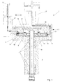
- Fig. 1 the longitudinal partial section through a spindle head 1 is shown, in which the drive of the high-speed spindle 2 takes place via compressed air.
- the exchangeable spindle head 1 essentially consists of a base body 1.1, on which the mandrel 3 and the adapter 4 for the compressed air supply 5 are arranged in the direction of the fixed part of the machine (not shown).
- the high-speed spindle 2 is rotatably supported in a cylindrical part 6 of the spindle head 1 via a plurality of bearings L.
- the cylindrical part 6 for the spindle bearing has a flange 8 at its end pointing in the direction of the mandrel 3 and is fastened via this to the base body 1.1 of the spindle head 1 by fastening elements 9.
- the high-speed spindle 2 has a turbine wheel 10 attached to it at its end.
- the turbine wheel 10 recesses 11 are provided on the mandrel side.
- the turbine wheel 10 has drive elements 12 in the manner of through openings with inclined surfaces.
- the radially circumferential surface 13 of the turbine wheel 10 serves as a braking surface and can also be provided with additional inclined surface elements which increase the braking effect.
- two permanent magnets 7, which are preferably glued are seated at an angle of 180 °.
- the Hall sensors 14 are arranged in the base body 1.1 at an angle of 135 ° on a printed circuit board 15 which is fastened by means of screws 16 and is advantageously additionally cast (for example with resin).
- a wiring 17, which is only partially shown, leads from the printed circuit board 15 to two infrared sensors 18, which are integrated in the adapter 4 for the compressed air supply (see FIG. 2).
- the secondary coil 19 is also seated in this adapter 4.
- the drive compressed air is guided by the compressed air supply 5 in the adapter 4 along the bores, which are marked with the through line, in the direction of the arrow thereof to the drive elements 12 of the turbine wheel 10.
- the brake air passes through a central through-hole along the holes marked with the dashed line in the direction of the arrow to the radially circumferential surface 13 of the turbine wheel 10.
- the assemblies arranged on the fixed part of the machine in the form of a primary coil, infrared receiver, evaluation circuit and external circuit are not shown. It works as follows: After changing the spindle head 1 into the fixed part of the machine via the mandrel 3, the compressed air connection 5 is also connected via the adapter 4. Driving compressed air can now be guided along the passage line marked with arrows in the direction of the arrow to the drive elements 12 of the turbine wheel 10.
- a voltage is induced in the secondary coil 19 via the primary coil (not shown), as a result of which the Hall sensors 14 and the infrared sensors 18 are supplied with current.
- a sensor signal is triggered in the opposite Hall sensors 14 by the magnets 7 arranged on the rotating part of the spindle head 1 (here on the turbine wheel 10). Due to the offset arrangement of the Hall sensors at an angle of 135 °, the flank of both sensor signals is offset in time.
- the signals pass through the cabling 17 to the two infrared sensors 18 and are thus transmitted wirelessly via two separate channels to the infrared receivers (not shown) on the fixed part of the machine and passed on to the evaluation module.
- the signal "spindle standstill" is forwarded to an external circuit by the evaluation module and is initiated via these measures to remove the spindle head.
- the two infrared transmission channels are monitored using a 1 Hz basic clock. If this cycle does not occur, the compressed air release of the drive air and the brake air is blocked.
- the evaluation module which is designed as a microcomputer, is monitored with the aid of an external reset circuit and the associated ⁇ C program is monitored with a watchdog. The state of the reset circuit and the watchdog are also made available to the external circuit. The signal is forwarded as an error message and the "spindle standstill" signal is not output.
- FIG. 3 shows the arrangement of the magnets 7 and the Hall sensors 14 as a schematic diagram.
- the magnets 7 are arranged at an angle of 180 ° and the Hall sensors 14 at an angle of 135 °.
- FIG. 4 shows the diagram of the two switching signals S1, S2 of the Hall sensors in clockwise rotation and FIG. 5 in counterclockwise rotation for one spindle revolution. During one revolution, two switching signals are triggered by the rotating magnets in each Hall sensor.
- the sensors for speed monitoring of the Fast spindle also on the inductive or capacitive Working principle.
- the wireless transmission to the evaluation module instead of using infrared sensors e.g. also done via radio.
Landscapes
- Engineering & Computer Science (AREA)
- Mechanical Engineering (AREA)
- Physics & Mathematics (AREA)
- General Physics & Mathematics (AREA)
- Arrangements For Transmission Of Measured Signals (AREA)
Applications Claiming Priority (2)
| Application Number | Priority Date | Filing Date | Title |
|---|---|---|---|
| DE2000141854 DE10041854A1 (de) | 2000-08-25 | 2000-08-25 | Drehzahlüberwachung, insbesondere Stillstandsüberwachung einer Werkzeugspindel, vorzugsweise einer, in einem auswechselbarem Spindelkopf gelagerten Schnellaufspindel |
| DE10041854 | 2000-08-25 |
Publications (1)
| Publication Number | Publication Date |
|---|---|
| EP1182006A2 true EP1182006A2 (fr) | 2002-02-27 |
Family
ID=7653805
Family Applications (1)
| Application Number | Title | Priority Date | Filing Date |
|---|---|---|---|
| EP01120310A Withdrawn EP1182006A2 (fr) | 2000-08-25 | 2001-08-24 | Surveillance de la vitesse de rotation, en particulier l'arrêt d'une broche porte-outil |
Country Status (2)
| Country | Link |
|---|---|
| EP (1) | EP1182006A2 (fr) |
| DE (1) | DE10041854A1 (fr) |
Cited By (4)
| Publication number | Priority date | Publication date | Assignee | Title |
|---|---|---|---|---|
| EP1932617A1 (fr) * | 2006-12-14 | 2008-06-18 | Gleason Cutting Tools Corporation | Axe de machine |
| EP3028804A1 (fr) * | 2014-12-04 | 2016-06-08 | SMW-AUTOBLOK Spannsysteme GmbH | Agencement de transmission, en particulier la transmission d'énergie et/ou de signal |
| EP3275593A1 (fr) * | 2016-07-25 | 2018-01-31 | DMG Mori Co., Ltd. | Machine-outil et procédé de détection |
| EP4474102A1 (fr) * | 2023-06-08 | 2024-12-11 | Pisek - Vitli Krpan, d.o.o. | Machine de coupe ou de séparation avec un ensemble de sécurité pour empêcher une utilisation incorrecte |
Families Citing this family (4)
| Publication number | Priority date | Publication date | Assignee | Title |
|---|---|---|---|---|
| DE102004050270B4 (de) * | 2004-10-14 | 2008-07-03 | Grotefeld Gmbh | Bearbeitungsaggregat |
| DE102006026193B3 (de) * | 2006-06-06 | 2008-01-31 | Grotefeld Gmbh | Winkelaggregat |
| DE102006056257B4 (de) * | 2006-11-27 | 2013-05-29 | Günther Zimmer | Einwechselaggregat mit Kleinmengenschmiermittelspender |
| DE102019124761A1 (de) * | 2019-09-13 | 2021-03-18 | Wto Vermögensverwaltung Gmbh | Angetriebener Werkzeughalter mit Mehrfach-Turbine |
Family Cites Families (1)
| Publication number | Priority date | Publication date | Assignee | Title |
|---|---|---|---|---|
| US5020968A (en) * | 1988-04-15 | 1991-06-04 | Ishikawajima-Harima Heavy Industries Co., Ltd. | System for controlling the rotating speed of a pneumatically driven spindle |
-
2000
- 2000-08-25 DE DE2000141854 patent/DE10041854A1/de not_active Withdrawn
-
2001
- 2001-08-24 EP EP01120310A patent/EP1182006A2/fr not_active Withdrawn
Cited By (7)
| Publication number | Priority date | Publication date | Assignee | Title |
|---|---|---|---|---|
| EP1932617A1 (fr) * | 2006-12-14 | 2008-06-18 | Gleason Cutting Tools Corporation | Axe de machine |
| US7462143B2 (en) | 2006-12-14 | 2008-12-09 | Gleason Cutting Tools Corporation | Machine spindle |
| CN101204791B (zh) * | 2006-12-14 | 2011-10-05 | 格里森刀具股份有限公司 | 机器心轴 |
| EP3028804A1 (fr) * | 2014-12-04 | 2016-06-08 | SMW-AUTOBLOK Spannsysteme GmbH | Agencement de transmission, en particulier la transmission d'énergie et/ou de signal |
| US10476277B2 (en) | 2014-12-04 | 2019-11-12 | Smw-Autoblok Spannsysteme Gmbh | Transmission arrangement such as for energy and/or signal transmission |
| EP3275593A1 (fr) * | 2016-07-25 | 2018-01-31 | DMG Mori Co., Ltd. | Machine-outil et procédé de détection |
| EP4474102A1 (fr) * | 2023-06-08 | 2024-12-11 | Pisek - Vitli Krpan, d.o.o. | Machine de coupe ou de séparation avec un ensemble de sécurité pour empêcher une utilisation incorrecte |
Also Published As
| Publication number | Publication date |
|---|---|
| DE10041854A1 (de) | 2002-03-21 |
Similar Documents
| Publication | Publication Date | Title |
|---|---|---|
| EP1882548B1 (fr) | Machine-outil à rotation améliorée | |
| EP0108857B1 (fr) | Mandrin de serrage actionné mécaniquement | |
| DE102007050111B4 (de) | Verfahren und Anlage-Sensorvorrichtung zu einer Anlagemessung bei einer Werkzeugmaschine | |
| DE69411262T2 (de) | Vorrichtung zum dynamischen auswuchten rotierender körper | |
| DE102013201328B4 (de) | Bearbeitungseinheit für eine programmgesteuerte Werkzeugmaschine | |
| DE2758275C2 (de) | Verfahren bzw. Einrichtung zum Außenrund- und Planschleifen | |
| WO2005115848A2 (fr) | Machine pour orienter et mettre en place des objets | |
| EP3040144A1 (fr) | Dispositif de serrage | |
| DE19712869A1 (de) | Lenkwinkelsensorsystem mit erhöhter Redundanz | |
| DE1477605C3 (de) | Vorrichtung zum Positionieren und Festspannen einer Werkstückplatte | |
| EP2311589A2 (fr) | Agrégat de serrage | |
| EP2925649A2 (fr) | Dispositif de réception d'une pièce pour un système rotatif de porte-pièce appartenant à une machine de production | |
| EP1182006A2 (fr) | Surveillance de la vitesse de rotation, en particulier l'arrêt d'une broche porte-outil | |
| EP0294547B1 (fr) | Cylindre de serrage circulant pour mandrin de serrage | |
| DE19733261C2 (de) | Rotations-Kantendreher mit direkt elektromagnetischem Antrieb für Webmaschinen | |
| EP1414606B1 (fr) | Outil rotatif a plusieurs tranchants | |
| DE19733262A1 (de) | Rotations-Kantendreher mit direkt elektromagnetischem Antrieb für Webmaschinen | |
| DE102008015435B4 (de) | Konusrändelwerkzeug | |
| EP1764186A1 (fr) | Système de contrôle d'une opération d'usinage avec des capteurs piézoélectriques axiaux dans la broche de travail | |
| DE102007057640B3 (de) | Werkzeugspanneinrichtung und Werkzeughalter | |
| DE19861417B4 (de) | Vorrichtung zum Verändern eines Zickzack-Musters bei einer Nähmaschine | |
| DE202004000212U1 (de) | Vorrichtung zur Drehzahlerkennung an Fräsköpfen beim mechanischen Entfernen von Ablagerungen an Schweißelektroden für das Widerstandsschweißen | |
| DE3930787A1 (de) | Einrichtung zur spanabhebenden bearbeitung, insbesondere fraeseinrichtung, fuer den werkzeugrevolver von werkzeugmaschinen | |
| DE102005042932A1 (de) | Druckmaschine, insbesondere Rollendruckmaschine | |
| DD264625A1 (de) | Einrichtung zur kontrolle der plananlage eines werkstuecks |
Legal Events
| Date | Code | Title | Description |
|---|---|---|---|
| PUAI | Public reference made under article 153(3) epc to a published international application that has entered the european phase |
Free format text: ORIGINAL CODE: 0009012 |
|
| 17P | Request for examination filed |
Effective date: 20010824 |
|
| AK | Designated contracting states |
Kind code of ref document: A2 Designated state(s): AT BE CH CY DE DK ES FI FR GB GR IE IT LI LU MC NL PT SE TR |
|
| AX | Request for extension of the european patent |
Free format text: AL;LT;LV;MK;RO;SI |
|
| STAA | Information on the status of an ep patent application or granted ep patent |
Free format text: STATUS: THE APPLICATION HAS BEEN WITHDRAWN |
|
| 18W | Application withdrawn |
Effective date: 20020402 |