EP1182010B1 - Schwingungsschraubenschlüssel - Google Patents
Schwingungsschraubenschlüssel Download PDFInfo
- Publication number
- EP1182010B1 EP1182010B1 EP99918392A EP99918392A EP1182010B1 EP 1182010 B1 EP1182010 B1 EP 1182010B1 EP 99918392 A EP99918392 A EP 99918392A EP 99918392 A EP99918392 A EP 99918392A EP 1182010 B1 EP1182010 B1 EP 1182010B1
- Authority
- EP
- European Patent Office
- Prior art keywords
- fly
- wrench
- wheel
- reduction gear
- output shaft
- Prior art date
- Legal status (The legal status is an assumption and is not a legal conclusion. Google has not performed a legal analysis and makes no representation as to the accuracy of the status listed.)
- Expired - Lifetime
Links
Images
Classifications
-
- B—PERFORMING OPERATIONS; TRANSPORTING
- B25—HAND TOOLS; PORTABLE POWER-DRIVEN TOOLS; MANIPULATORS
- B25B—TOOLS OR BENCH DEVICES NOT OTHERWISE PROVIDED FOR, FOR FASTENING, CONNECTING, DISENGAGING, OR HOLDING
- B25B21/00—Portable power-driven screw or nut setting or loosening tools; Attachments for drilling apparatus serving the same purpose
- B25B21/02—Portable power-driven screw or nut setting or loosening tools; Attachments for drilling apparatus serving the same purpose with means for imparting impact to screwdriver blade or nut socket
-
- B—PERFORMING OPERATIONS; TRANSPORTING
- B25—HAND TOOLS; PORTABLE POWER-DRIVEN TOOLS; MANIPULATORS
- B25B—TOOLS OR BENCH DEVICES NOT OTHERWISE PROVIDED FOR, FOR FASTENING, CONNECTING, DISENGAGING, OR HOLDING
- B25B21/00—Portable power-driven screw or nut setting or loosening tools; Attachments for drilling apparatus serving the same purpose
Definitions
- the invention belongs to portable hand tools with power drive using for assembling and disassembling of threaded connections and can be used for mechanization of installation works in different branches of industry.
- the electrical vibration wrench the inventor's certificate SU, A, 967791 , is additionally supplied with an ordinary free-wheel two-way clutch, the hoop of which is fixed strictly on the outer shaft of the drive's rotor, the warpage fork is strictly connected to the planet carrier of the reduction gear and the hub of the sprocket wheel is fixed so that it can rotate relatively the outer shaft of the rotor and is connected to the warpage fork though the spiral spring.
- the wrench contains the body with the handle, the power drive with the output shaft and the exciter of rotary oscillations located inside.
- debalanced shafts Into the body of the exciter of rotary oscillations there are placed debalanced shafts, the reduction gear and the spindle with the head for a wrench on its end.
- the spindle is strictly connected to the body of the exciter of rotary oscillations, and the reduction gear has cog-wheels with outer cogs mounted on the appropriate debalanced shaft, its cogs are in geared mesh with the cog-wheel with inner cogs, which is kinematically connected to the output shaft of the drive.
- the closest document in its technical essence and the achieved effect is the vibration nut wrench by the RU 2081741 C1 patent.
- the wrench contains a body with a control handle, a drive means with an output shaft being disposed within the body, a means for generating rotational oscillations being connected to the output shaft of the drive means, the means for generating rotational oscillations comprising, in series, a first fly-wheel, a mechanism of variable speed of rotation, a planetary reduction gear and a second fly wheel, a planet carrier of the planetary reduction gear is directly connected to an output spindle of the wrench, which has a wrench head on its end.
- the drive When screwing a nut freely, the drive, through the mechanism of variable speed, turns the carrier of the planetary reduction gear that has far less mass than the fly-wheel.
- the carrier When the nut contacts the surface of the screwed detail, the carrier is stopped and the fly-wheel increase revolutions, putting in action the exciter of the rotary oscillations and tightening the threaded connection.
- the construction of the known vibration nut wrench provides vibration oscillations of the exciter of rotary oscillations, under which the tightening torque will be more than the untightening torque. But the known nut wrench does not utilize energies of the fly-wheels because of faint difference between the amplitudes of vibration tightening and untightening torques. Besides, the known nut wrench does not allow to choose the most effective mode that minimizes the friction in thread.
- the invention is based on the idea of increasing the amplitude difference of the shaft's turning when screwing and unscrewing and, thus, achieve a greater total vibration screwing torque and so to increase the effectiveness of the action of the vibration wrench.
- the raised problem is solved in the vibration nut wrench containing a body with a control handle, a drive means with an output shaft being disposed within the body, a means for generating rotational oscillations being connected to the output shaft of the drive means, the means for generating rotational oscillations comprising, in series, a first fly-wheel, a mechanism of variable speed of rotation, a planetary reduction gear and a second fly wheel , a planet carrier of the planetary reduction gear is directly connected to an output spindle of the wrench, which ha a wrench head on its end, wherein the second fly wheel which is located on the side of the planetary reduction gear is provided with a brake arrangement.
- the brake device in the proposed vibration nut wrench makes it possible to provide additional damping of the fly-wheel of the exciter of rotary oscillations located on the side of the planetary reduction gear.
- the brake arrangement can be either with variable, or with constant braking effort. As a result of all this the turn amplitude of the drive and the associated shaft in the unscrewing direction is decreased, while in screwing direction it grows up, i.e., the difference between them is increased, and the total vibration torque will be directed to screwing.
- the possibility of regulation of the amplitude of oscillations makes it possible to find out the most effective operating mode, achieving the minimal friction in thread. All this will increase the effectiveness of the vibration wrench.
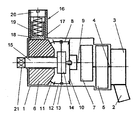
- the vibration nut wrench contains a body 1 with a control handle 2.
- a drive 3 and an exciter of rotary oscillations connected to its output shaft 4.
- the exciter of the rotary oscillations is designed in the form of two fly-wheels 5 and 6 connected between each other by the mechanism of variable speed of rotation 7 and a planetary reduction gear 8.
- the mechanism of variable speed of rotation 7 and the planetary reduction gear 8 can be designed in different ways.
- the mechanism of variable speed of rotation can be designed in the known way from gears of non-circle form or in the form of link gear, and the planetary mechanism can be conic, cylindrical, or frictional.
- the fly-wheel 5 is located on the output shaft 4 of the drive 3 connected also to the mechanism of variable speed of rotation 7, a shaft 9 of which is connected to a central (solar) pinion 10 of the planetary reduction gear 8.
- Another pinion II of the reduction gear 8 (epicycle) is strictly connected to the second fly-wheel 6 of the exciter of the rotary oscillations.
- the central pinions 10 and 11 are connected to each other by the satellites 12 fixed on the axes 13, which are strictly fixed on a carrier 14.
- the carrier 14 of the planetary reduction gear 8 is connected just to a spindle 15 of the wrench.
- the fly-wheel 6 of the exciter of rotary oscillations is supplied with a brake arrangement 16 that is designed as a shell 17 welded to the body 1.
- a brake block 18 (designed in any form) jammed to a fly-wheel 19 by the spring 19.
- the amount of hold-down pressure of the brake block 18 is regulated by a threaded plug 20.
- a square 21 for setting of interchangeable heads (not displayed in the figure) by a wrench.
- the brake arrangement can be designed in many ways, for example, with use of known constructions of electromagnetic clutches, compressed air, i.e., with a turbine on the fly-wheel, permanent magnets, hydrodynamic clutches etc.
- the vibration nut wrench works as follows. By screwing the threaded plug 20 of the brake arrangement 16 it is set the desired amount of hold-down pressure of the brake block to the fly-wheel 6, this pressure is supported during the whole process of screwing or unscrewing of threaded connections.
- the interchangeable working head (not displayed) is fixed on the nut (screwbolt) of a threaded connection.
- the drive 3 After pushing the button of the starting device (not displayed) the drive 3 is switched on transferring rotation through the output shaft 4 to the fly-wheel 5 and to the output shaft 9 of the mechanism of variable speed of rotation 7.
- the output shaft 9, in its turn, transfers rotation to the central solar pinion 10 of the planetary reduction gear 8, which, in its turn, through the satellites 12, initiate rotation of another central pinion (epicycle) 11 of the planetary reduction gear 8 and to the fly-wheel 6.
- the output shaft 9 of the mechanism of variable speed 7 has variable speed when rotating, i.e., its rotation accelerates or slows down.
- the brake arrangement 16 can become uncontrollable, for example, when constant magnets are used for braking.
- the invention can be used in hand portable tools with power drive designed for assembling and disassembling of threaded connections, screwing on and screwing out of screws, chasing, drilling.
Landscapes
- Engineering & Computer Science (AREA)
- Mechanical Engineering (AREA)
- Details Of Spanners, Wrenches, And Screw Drivers And Accessories (AREA)
- Nonmetallic Welding Materials (AREA)
- Consolidation Of Soil By Introduction Of Solidifying Substances Into Soil (AREA)
- Injection Moulding Of Plastics Or The Like (AREA)
- Nitrogen And Oxygen Or Sulfur-Condensed Heterocyclic Ring Systems (AREA)
- Percussive Tools And Related Accessories (AREA)
- Gripping On Spindles (AREA)
Claims (1)
- Vibrations-Schraubenschlüssel, umfassend ein Gehäuse (1) mit einem Steuerhebel (2), ein Antriebsmittel (3) mit einer Ausgangswelle (4), die im Gehäuse (1) angeordnet ist, eine Einrichtung zum Erzeugen von Drehschwingungen, die in die Ausgangswelle (4) des Antriebsmittels (3) eingekoppelt werden, wobei die Einrichtung zum Erzeugen von Drehschwingungen hintereinander ein erstes Schwungrad (5), einen Mechanismus (7) mit variabler Drehgeschwindigkeit, ein Planeten-Untersetzungsgetriebe (8) und ein zweites Schwungrad (6) umfasst, und wobei ein Planetenträger (14) des Planeten-Untersetzungsgetriebes (8) direkt mit einer Ausgangsspindel (15) des Schraubenschlüssels verbunden ist, die an ihrem Ende einen Schraubenschlüsselkopf (21) aufweist,
dadurch gekennzeichnet, dass
das zweite Schwungrad (6), das auf der Seite des Planeten-Untersetzungsgetriebes (8) angeordnet ist, mit einer Bremsanordnung (16) versehen ist.
Applications Claiming Priority (2)
| Application Number | Priority Date | Filing Date | Title |
|---|---|---|---|
| RU98106646/28A RU2182533C2 (ru) | 1998-04-03 | 1998-04-03 | Вибрационный гайковерт |
| PCT/RU1999/000094 WO1999051403A1 (fr) | 1998-04-03 | 1999-03-26 | Serreuse vibrante |
Publications (3)
| Publication Number | Publication Date |
|---|---|
| EP1182010A1 EP1182010A1 (de) | 2002-02-27 |
| EP1182010A4 EP1182010A4 (de) | 2006-08-09 |
| EP1182010B1 true EP1182010B1 (de) | 2008-01-16 |
Family
ID=20204539
Family Applications (1)
| Application Number | Title | Priority Date | Filing Date |
|---|---|---|---|
| EP99918392A Expired - Lifetime EP1182010B1 (de) | 1998-04-03 | 1999-03-26 | Schwingungsschraubenschlüssel |
Country Status (10)
| Country | Link |
|---|---|
| US (1) | US6631659B1 (de) |
| EP (1) | EP1182010B1 (de) |
| JP (1) | JP2002534274A (de) |
| CN (1) | CN1154553C (de) |
| AT (1) | ATE383926T1 (de) |
| AU (1) | AU3632699A (de) |
| CA (1) | CA2369353A1 (de) |
| DE (1) | DE69938010D1 (de) |
| RU (1) | RU2182533C2 (de) |
| WO (1) | WO1999051403A1 (de) |
Families Citing this family (6)
| Publication number | Priority date | Publication date | Assignee | Title |
|---|---|---|---|---|
| DE102004037072B3 (de) * | 2004-07-30 | 2006-01-12 | Hilti Ag | Handwerkzeuggerät mit Drehimpuls- und Bremskrafterzeuger |
| CN102305275A (zh) * | 2011-08-17 | 2012-01-04 | 冯谷宝 | 多功能功率增力器 |
| US10099351B2 (en) | 2013-08-08 | 2018-10-16 | Atlas Copco Industrial Technique Ab | Torque delivering power tool with flywheel |
| JP6335296B2 (ja) * | 2013-08-08 | 2018-05-30 | アトラス・コプコ・インダストリアル・テクニーク・アクチボラグ | フライホイールを備えた動力工具及び該フライホイールを加速するギア |
| CN108274227B (zh) * | 2018-03-05 | 2023-09-26 | 王聪 | 用于螺栓连接构件的自动松紧装置及其工作方法 |
| CN114336434B (zh) * | 2021-12-24 | 2022-10-11 | 泰州市达维电器有限公司 | 一种适用于建筑电气管道的穿线器 |
Family Cites Families (8)
| Publication number | Priority date | Publication date | Assignee | Title |
|---|---|---|---|---|
| US3886821A (en) * | 1974-07-19 | 1975-06-03 | Nippon Concrete Ind Co Ltd | Automatic fastening device with bolts for concrete molds |
| SU795927A1 (ru) * | 1978-11-13 | 1981-01-15 | Брянский технологический институт | Электрический вибрационныйгАйКОВЕРТ |
| SU891418A1 (ru) * | 1980-05-05 | 1981-12-23 | Челябинский Политехнический Институт Им.Ленинского Комсомола | Гайковерт инерционный |
| SU967791A2 (ru) * | 1980-10-16 | 1982-10-23 | Брянский Ордена Трудового Красного Знамени Технологический Институт | Электрический вибрационный гайковерт |
| NO158490C (no) * | 1986-04-18 | 1988-09-21 | Kverneland As | Muttertrekker. |
| RU1771943C (ru) * | 1990-02-26 | 1992-10-30 | Брянский технологический институт | Вибрационный гайковерт |
| JPH0731277U (ja) | 1993-11-11 | 1995-06-13 | 前田金属工業株式会社 | ナット締付機 |
| RU2081741C1 (ru) * | 1994-08-12 | 1997-06-20 | Иван Васильевич Стариков | Вибрационный гайковерт |
-
1998
- 1998-04-03 RU RU98106646/28A patent/RU2182533C2/ru not_active IP Right Cessation
-
1999
- 1999-03-26 DE DE69938010T patent/DE69938010D1/de not_active Expired - Lifetime
- 1999-03-26 US US09/937,436 patent/US6631659B1/en not_active Expired - Fee Related
- 1999-03-26 EP EP99918392A patent/EP1182010B1/de not_active Expired - Lifetime
- 1999-03-26 CN CNB998166677A patent/CN1154553C/zh not_active Expired - Fee Related
- 1999-03-26 CA CA002369353A patent/CA2369353A1/en not_active Abandoned
- 1999-03-26 AT AT99918392T patent/ATE383926T1/de not_active IP Right Cessation
- 1999-03-26 WO PCT/RU1999/000094 patent/WO1999051403A1/ru not_active Ceased
- 1999-03-26 AU AU36326/99A patent/AU3632699A/en not_active Abandoned
- 1999-03-26 JP JP2000542153A patent/JP2002534274A/ja active Pending
Also Published As
| Publication number | Publication date |
|---|---|
| CA2369353A1 (en) | 1999-10-14 |
| RU2182533C2 (ru) | 2002-05-20 |
| CN1154553C (zh) | 2004-06-23 |
| WO1999051403A1 (fr) | 1999-10-14 |
| AU3632699A (en) | 1999-10-25 |
| JP2002534274A (ja) | 2002-10-15 |
| CN1367728A (zh) | 2002-09-04 |
| US6631659B1 (en) | 2003-10-14 |
| EP1182010A4 (de) | 2006-08-09 |
| EP1182010A1 (de) | 2002-02-27 |
| DE69938010D1 (de) | 2008-03-06 |
| ATE383926T1 (de) | 2008-02-15 |
Similar Documents
| Publication | Publication Date | Title |
|---|---|---|
| US8631880B2 (en) | Power tool with impact mechanism | |
| CN103619542B (zh) | 电脉冲螺丝刀 | |
| US3866492A (en) | Torque multiplier | |
| US6631659B1 (en) | Vibrating nutrunner | |
| JP4989856B2 (ja) | 補助ハンドル付き回転駆動の手工具 | |
| JP2006212764A5 (de) | ||
| CN102387896B (zh) | 冲击工具 | |
| CN100475450C (zh) | 电动螺丝刀 | |
| CN216483935U (zh) | 一种航空作动装置用离合器的自动磨合装置 | |
| CN101699018B (zh) | 自动无级变速钻修井顶驱 | |
| CN212330860U (zh) | 一种电动螺母预装工具 | |
| RU2081741C1 (ru) | Вибрационный гайковерт | |
| CN211388508U (zh) | 一种便捷式扳手 | |
| CN203765536U (zh) | 一种螺丝刀变速棘轮装置及其螺丝刀 | |
| CN2193234Y (zh) | 一种紧固工具 | |
| SU891418A1 (ru) | Гайковерт инерционный | |
| CN201579741U (zh) | 动力工具 | |
| CN201535135U (zh) | 自动无级变速钻修井顶驱 | |
| CN222702068U (zh) | 带悬浮扭簧的动力传动机构 | |
| CN221494257U (zh) | 一种角钻锁止结构 | |
| CN220882154U (zh) | 一种便于更换套筒的电动扳手 | |
| CN2319236Y (zh) | 四头手动拆轮工具 | |
| CN2782270Y (zh) | 充电式多用电钻 | |
| CN2099647U (zh) | 增力可调螺丝松紧器 | |
| CN206561379U (zh) | 一种具有防转死装置的新型电动螺丝刀 |
Legal Events
| Date | Code | Title | Description |
|---|---|---|---|
| PUAI | Public reference made under article 153(3) epc to a published international application that has entered the european phase |
Free format text: ORIGINAL CODE: 0009012 |
|
| 17P | Request for examination filed |
Effective date: 20011026 |
|
| AK | Designated contracting states |
Kind code of ref document: A1 Designated state(s): AT BE CH DE ES FI FR GB IT LI NL PT SE |
|
| A4 | Supplementary search report drawn up and despatched |
Effective date: 20060706 |
|
| 17Q | First examination report despatched |
Effective date: 20061214 |
|
| GRAP | Despatch of communication of intention to grant a patent |
Free format text: ORIGINAL CODE: EPIDOSNIGR1 |
|
| GRAS | Grant fee paid |
Free format text: ORIGINAL CODE: EPIDOSNIGR3 |
|
| GRAA | (expected) grant |
Free format text: ORIGINAL CODE: 0009210 |
|
| AK | Designated contracting states |
Kind code of ref document: B1 Designated state(s): AT BE CH DE ES FI FR GB IT LI NL PT SE |
|
| REG | Reference to a national code |
Ref country code: GB Ref legal event code: FG4D |
|
| REG | Reference to a national code |
Ref country code: CH Ref legal event code: EP |
|
| REF | Corresponds to: |
Ref document number: 69938010 Country of ref document: DE Date of ref document: 20080306 Kind code of ref document: P |
|
| PG25 | Lapsed in a contracting state [announced via postgrant information from national office to epo] |
Ref country code: NL Free format text: LAPSE BECAUSE OF FAILURE TO SUBMIT A TRANSLATION OF THE DESCRIPTION OR TO PAY THE FEE WITHIN THE PRESCRIBED TIME-LIMIT Effective date: 20080116 |
|
| NLV1 | Nl: lapsed or annulled due to failure to fulfill the requirements of art. 29p and 29m of the patents act | ||
| PG25 | Lapsed in a contracting state [announced via postgrant information from national office to epo] |
Ref country code: LI Free format text: LAPSE BECAUSE OF FAILURE TO SUBMIT A TRANSLATION OF THE DESCRIPTION OR TO PAY THE FEE WITHIN THE PRESCRIBED TIME-LIMIT Effective date: 20080116 Ref country code: FI Free format text: LAPSE BECAUSE OF FAILURE TO SUBMIT A TRANSLATION OF THE DESCRIPTION OR TO PAY THE FEE WITHIN THE PRESCRIBED TIME-LIMIT Effective date: 20080116 Ref country code: ES Free format text: LAPSE BECAUSE OF FAILURE TO SUBMIT A TRANSLATION OF THE DESCRIPTION OR TO PAY THE FEE WITHIN THE PRESCRIBED TIME-LIMIT Effective date: 20080427 Ref country code: CH Free format text: LAPSE BECAUSE OF FAILURE TO SUBMIT A TRANSLATION OF THE DESCRIPTION OR TO PAY THE FEE WITHIN THE PRESCRIBED TIME-LIMIT Effective date: 20080116 |
|
| REG | Reference to a national code |
Ref country code: CH Ref legal event code: PL |
|
| PG25 | Lapsed in a contracting state [announced via postgrant information from national office to epo] |
Ref country code: AT Free format text: LAPSE BECAUSE OF FAILURE TO SUBMIT A TRANSLATION OF THE DESCRIPTION OR TO PAY THE FEE WITHIN THE PRESCRIBED TIME-LIMIT Effective date: 20080116 |
|
| PG25 | Lapsed in a contracting state [announced via postgrant information from national office to epo] |
Ref country code: PT Free format text: LAPSE BECAUSE OF FAILURE TO SUBMIT A TRANSLATION OF THE DESCRIPTION OR TO PAY THE FEE WITHIN THE PRESCRIBED TIME-LIMIT Effective date: 20080616 Ref country code: BE Free format text: LAPSE BECAUSE OF FAILURE TO SUBMIT A TRANSLATION OF THE DESCRIPTION OR TO PAY THE FEE WITHIN THE PRESCRIBED TIME-LIMIT Effective date: 20080116 |
|
| PG25 | Lapsed in a contracting state [announced via postgrant information from national office to epo] |
Ref country code: SE Free format text: LAPSE BECAUSE OF FAILURE TO SUBMIT A TRANSLATION OF THE DESCRIPTION OR TO PAY THE FEE WITHIN THE PRESCRIBED TIME-LIMIT Effective date: 20080416 |
|
| EN | Fr: translation not filed | ||
| PLBE | No opposition filed within time limit |
Free format text: ORIGINAL CODE: 0009261 |
|
| STAA | Information on the status of an ep patent application or granted ep patent |
Free format text: STATUS: NO OPPOSITION FILED WITHIN TIME LIMIT |
|
| 26N | No opposition filed |
Effective date: 20081017 |
|
| GBPC | Gb: european patent ceased through non-payment of renewal fee |
Effective date: 20080416 |
|
| PG25 | Lapsed in a contracting state [announced via postgrant information from national office to epo] |
Ref country code: DE Free format text: LAPSE BECAUSE OF FAILURE TO SUBMIT A TRANSLATION OF THE DESCRIPTION OR TO PAY THE FEE WITHIN THE PRESCRIBED TIME-LIMIT Effective date: 20080417 |
|
| PG25 | Lapsed in a contracting state [announced via postgrant information from national office to epo] |
Ref country code: FR Free format text: LAPSE BECAUSE OF FAILURE TO SUBMIT A TRANSLATION OF THE DESCRIPTION OR TO PAY THE FEE WITHIN THE PRESCRIBED TIME-LIMIT Effective date: 20081107 |
|
| PG25 | Lapsed in a contracting state [announced via postgrant information from national office to epo] |
Ref country code: GB Free format text: LAPSE BECAUSE OF NON-PAYMENT OF DUE FEES Effective date: 20080416 |
|
| PG25 | Lapsed in a contracting state [announced via postgrant information from national office to epo] |
Ref country code: IT Free format text: LAPSE BECAUSE OF FAILURE TO SUBMIT A TRANSLATION OF THE DESCRIPTION OR TO PAY THE FEE WITHIN THE PRESCRIBED TIME-LIMIT Effective date: 20080116 |