EP1182062B2 - Attelage de remorque - Google Patents
Attelage de remorque Download PDFInfo
- Publication number
- EP1182062B2 EP1182062B2 EP01128747.1A EP01128747A EP1182062B2 EP 1182062 B2 EP1182062 B2 EP 1182062B2 EP 01128747 A EP01128747 A EP 01128747A EP 1182062 B2 EP1182062 B2 EP 1182062B2
- Authority
- EP
- European Patent Office
- Prior art keywords
- clamping
- elements
- trailer coupling
- coupling according
- actuating means
- Prior art date
- Legal status (The legal status is an assumption and is not a legal conclusion. Google has not performed a legal analysis and makes no representation as to the accuracy of the status listed.)
- Expired - Lifetime
Links
Images


Classifications
-
- B—PERFORMING OPERATIONS; TRANSPORTING
- B60—VEHICLES IN GENERAL
- B60D—VEHICLE CONNECTIONS
- B60D1/00—Traction couplings; Hitches; Draw-gear; Towing devices
- B60D1/24—Traction couplings; Hitches; Draw-gear; Towing devices characterised by arrangements for particular functions
- B60D1/246—Traction couplings; Hitches; Draw-gear; Towing devices characterised by arrangements for particular functions for actuating the hitch by powered means
-
- B—PERFORMING OPERATIONS; TRANSPORTING
- B60—VEHICLES IN GENERAL
- B60D—VEHICLE CONNECTIONS
- B60D1/00—Traction couplings; Hitches; Draw-gear; Towing devices
- B60D1/48—Traction couplings; Hitches; Draw-gear; Towing devices characterised by the mounting
- B60D1/52—Traction couplings; Hitches; Draw-gear; Towing devices characterised by the mounting removably mounted
-
- B—PERFORMING OPERATIONS; TRANSPORTING
- B60—VEHICLES IN GENERAL
- B60D—VEHICLE CONNECTIONS
- B60D1/00—Traction couplings; Hitches; Draw-gear; Towing devices
- B60D1/48—Traction couplings; Hitches; Draw-gear; Towing devices characterised by the mounting
- B60D1/54—Traction couplings; Hitches; Draw-gear; Towing devices characterised by the mounting collapsible or retractable when not in use, e.g. hide-away hitches
Definitions
- the invention relates to a towing hitch for motor vehicles, comprising a vehicle-mounted bearing part and a bearing part mounted on the pivoting part with a ball neck and a coupling ball, which is pivotable relative to the bearing part about a pivot axis between a rest position and a working position.
- a trailer coupling according to the preamble of claim 1 is already in the German patent application DE-195 21 896 described.
- the invention has for its object to provide a trailer hitch of the generic type such that it is safe and easy to fix in the working position.
- an actuator also includes the Verspanngetriebe, when operating the actuator not only the movement of the support member between the locking position and the release position is possible, but also the movement of the same from the clamping position to the release position and vice versa.
- the trailer coupling according to the invention can be actuated by the fact that the actuator has a single drive element, upon actuation of the support member, in each of the release position, the blocking position, the release position and the clamping position comprehensive positions can be brought.
- a bracing can be designed in various ways.
- the bracing could be designed so that it can move in the direction of the release position opposite to this even when acting on this reaction force when bracing the stop elements and support elements from the bracing position.
- the Verspanngetriebe would be to realize that the Verspanngetriebe is designed as a wedge gear.
- a wedge gear is the simplest way to realize a Verspanngetriebes, especially if this is to be designed to be self-locking.
- the support elements are arranged on the bearing part when, by means of the bracing mechanism, one of the support elements is movable in the direction of the corresponding stop element.
- a preferred embodiment of such an actuator provides that this moves to fix the pivot member in the working position, the support member from the release position to the locked position and transferred after reaching the locking position, the bracing of the release position in the clamping position and to release the pivoting part of the bracing of the clamping position is transferred to the release position and then moves the movable member from the blocking position to the release position.
- the actuating device is designed so that it moves the movable element positively controlled from the release position to the blocking position and in particular also vice versa.
- the actuating device and the Verspanngetriebe positively controlled moves from the release position to the clamping position and in particular also vice versa.
- a positive control is also advantageous if it is possible to move from the clamping position into the release position, as this can also be used to overcome the jamming of the respective movable element, for example the support element.
- the actuating device has two successive in a position acting on the support member movable wedge elements, wherein one of the wedge elements for transferring the support member from the release position to the blocking position and the other of the wedge elements for transferring the support member from the release position in the Clamping position is used.
- a clamping force generating unit is preferably provided which cooperates with the actuating device and which the actuating device in the direction of actuation in the blocking position of the movable element, for example, the support element, and the tensioning position of the tensioning transmission is acted upon by a force.
- the clamping force generating unit is designed so that it has a force accumulator, which acts on the actuating device for reaching the blocking position and the clamping position and which is to counteract to reach the release position and the release position.
- the support member from the blocking position is preferably provided that the clamping force generating unit is provided with a blocking device which counteract at a non-actuation of the same to the clamping force memory, a leaving blocked the blocking position in the direction of the release position.
- the blocking device is designed so that it must first be solved before the possibility exists to counteract the tension memory.
- a particularly favorable design solution provides that the blocking device is releasable upon actuation of the clamping force generating unit to reach the release position and thus automatically such a movement in the direction of the release position upon actuation of the clamping force generating unit is possible.
- the clamping force generating unit has an operating element, with which first the blocking device releasably and then with an unlocking force on the actuator can be acted.
- a particularly favorable solution provides that the actuating device and the movable support element forms an assembly which can be mounted as a whole on the bearing part.
- the provision of a separate, to be mounted on the bearing part and independent of this assembly also provides the ability to adjust the actuator together with the movable member, such as the support member, adjustable to the bearing member, so that there is the possibility of a simultaneous adjustment with the assembly of the actuator make the same and with this an adjustment of the held by this support member relative to the bearing part.
- the pivot member has two spaced-apart stop elements, that the bearing part is provided with two support elements and that for fixing the ball neck in the working position of the support elements and one of the stop elements in the sense of a pivoting movement of the ball neck in a first direction cooperate, which counteract the other of the support elements and the other of the stop elements, and that in this case the stop elements and the support elements are playable against each other can be applied.
- the advantage of the solution according to the invention is the fact that is given by the provision of two cooperating pairs of stop elements and support elements the opportunity to play this pairwise without play together and thereby to obtain a permanently backlash-free and thus permanently low-wear fixation of the pivot member relative to the bearing part , It has been shown that the play-free abutment of the cooperating pairs of each one of the stop elements and support elements maximum wear in the region thereof and thus also in the fixation of the pivoting part can be achieved.
- the adjustability of the one element can then be realized particularly favorable if it is movably mounted in the clamping direction.
- Such a movable mounting of one of the elements can be realized either by a linear mobility of the same or with a derived from a rotational movement linear mobility of the element.
- stop elements rotate on different tracks around the pivot axis, that is, when each of the stop elements has its own path, with which it rotates about the pivot axis. This is a particularly simple assignment of the individual stop elements in terms of the corresponding with these support elements realized in terms of space.
- the second of the stop elements is designed as a fixedly arranged on the pivot member element.
- one of the stop elements is disposed on a comb of the pivoting part, which has a greater distance from the pivot axis than, for example, a bearing body of the pivot part, which surrounds a pivot pin.
- the ball neck extends away from the pivoting part and thus inevitably extends with increasing radius from the axis, it is preferably provided that another of the stop elements is arranged on a subsequent to the pivoting part neck of the ball neck.
- an advantageous embodiment provides that a first of the support elements is arranged in a viewed in the direction of travel rear portion of the bearing part.
- a second of the support elements is arranged in a front region of the bearing part viewed in the direction of travel, while in another embodiment, the second support element is arranged in the rear region of the bearing part.
- a particularly preferred because of their constructive simplicity solution provides that one of the support elements is arranged as always in the path of the corresponding stop element projecting support member on the bearing part and thus, for example, is always acted upon by the stop element when it is in the working position.
- the movable support member is hineinbewegbar by a linear displacement in the path of the stop element.
- Another preferred embodiment provides that the movable support element is hineinschwenkbar in the path of the corresponding stop element.
- an actuating device for the support element is preferably provided, which serves to support the support element for these movements and act upon.
- An embodiment of such an actuating device comprises an actuating wedge in order to move the guided in a guide guided support member between the blocking position and the release position.
- the actuating device comprises a pivot bearing and a pivot drive for the movable support member.
- a first embodiment of a trailer coupling according to the invention includes a fixedly mounted on the vehicle bearing part 10 which is mounted, for example, on a fixedly connected to the body cross member and about a pivot axis 12 relative to the bearing part 10 pivotable pivot member 14, on which a ball neck 16 is held, at its the pivoting part 14 opposite and curved end 18 carries a designated as a whole with 20 coupling ball.
- the pivot axis 12 is an axis which is inclined both with respect to a vertical V and with respect to a horizontal H and a vehicle longitudinal direction 30, for example as in the German patent application 196 12 959.1 described.
- the ball neck 16 is pivotable from a working position in which its longitudinal direction 22 extends approximately parallel to the longitudinal direction 30 of the motor vehicle into a rest position in which the longitudinal direction 22 is approximately transverse to the longitudinal direction 30 of the vehicle and the coupling ball 20 down to the roadway points, while in the working position, the coupling ball 20 has due to the curved end 18 of the ball neck 16 in a known manner upwards.
- bearing pin 24 For pivotable mounting of the pivoting part 14 about the pivot axis 12, this is mounted on a bearing pin 24 which engages with its opposite ends 26 and 28 in bearing bores 32 and 34 of bearing flanges 36 and 38 of the bearing part 10.
- bearing flanges 36 and 38 extend starting from a mounting plate 40 of the bearing part 10 downwards, preferably in the direction of the road and are through a rear wall 42 of the bearing part 10, which also extends from the mounting plate 40 in the same direction as the bearing flanges 36 and 38 , connected with each other.
- the bearing flanges 36 and 38 extend obliquely to the longitudinal direction 30 of the motor vehicle.
- a first support member 50 is provided on the bearing part 10, in a lower region of the rear wall 42 thereof, which has a first support surface 52 which faces the working neck ball neck 16 and on which a first stop surface 54 can be applied is, which is arranged on a trained as a first stop element and the support member 50 in the working position approach 56 of the ball neck, which adjoins substantially directly to the pivot member 14, and also a web 55 about the pivot axis 12 is movable.
- the first support member 50 and the first stop member 56 thus limit pivotal movement of the ball neck 16 in the direction of a pivoting direction 58 about the pivot axis 12, which corresponds to the pivoting direction 58 of the ball neck 16 from the rest position to the working position.
- a locking ball 60 which is displaceably guided on the bearing part 10, serves as a second support surface with a spherical surface 62 on a second stop surface 64, which is similar to a dome a recess 66 arranged in the pivoting part 14 and forming a second stop element acts, wherein the recess 66 is arranged in a comb area 68 of the pivoting part 14, which has the greatest possible radial distance from the pivoting axis 12 and on a path 65 which has a larger radius as the web 55 is movable about the pivot axis.
- the pivoting part 14 preferably comprises a bearing body 71 surrounding the bearing pin 24 and a truncated cone-like section extending radially therefrom, which forms the comb area 68, wherein the recess 66 is arranged in a conical surface 70 of the truncated cone-like section.
- the second support surface 62 preferably runs obliquely relative to a movement direction 72 of the preferably linearly movable second support element designed as a locking ball 60 and rests against a region of the spherical surface 74 of the locking ball 60 that also extends obliquely to the direction of movement, the abutment surface 64 and the support surface 62 cooperating in this way in that after a first contact of the abutment surface 64 and the support surface 62 and further movement of the locking ball 60 in a clamping direction 72a to the abutment surface, the pivoting member 14 experiences such torque about the axis 12 causing the ball neck 14 to move in the pivoting direction 58, which is then limited by the first support member 50 and the first stop member 56 is prevented when they abut each other.
- the support members 50 and 60 and the stop members 56 and 66 together act such that the first support surface 52 on the first stop surface 54 and the second support surface 62 on the second stop surface 64 always rest without play and the ball neck 16 backlash in its working position hold, where - as will be explained in detail below - even a distortion of the stop surfaces 54, 64 relative to the support surfaces 52, 62 takes place.
- a guide bush 74 is provided, which is fixed on the bearing part 10 and is preferably inserted in a recess provided for this in the rear wall 42.
- the locking ball 60 is characterized by an actuator generally designated 80 comprising a spline gear comprising a wedge body 82, one of Fig. 2 dashed lines release position in the in Fig. 2 solidly drawn locking position movable, wherein the locking ball 60 is moved in the release position so far away from the recess 66, that the recess 66 is freely movable on its predetermined by the pivot axis 12 track 65, while the locking ball 60 in the locked position in the recess 66th engages and thus blocks the movement of the recess 66 along the path 65.
- an actuator generally designated 80 comprising a spline gear comprising a wedge body 82, one of Fig. 2 dashed lines release position in the in Fig. 2 solidly drawn locking position movable, wherein the locking ball 60 is moved in the release position so far away from the recess 66, that the recess 66 is freely movable on its predetermined by the pivot axis 12 track 65, while the locking ball 60 in the locked
- To move the locking ball 60 from the release position to the blocking position of the wedge body 82 includes a front side thereof arranged adjusting wedge 84 with a locking bevel 86 which serves to move the locking ball 60 from the release position into a blocking position, which is already reached when the locking ball 60 rests on a locking surface 88, which extends parallel to a displacement direction 90 of the sliding wedge 82, in contrast to the obliquely to the direction 90 extending bevel 86.
- the locking surface 88 also serves to secure the wedge body 82 against movement in the direction of displacement 90, in which the sliding wedge permits movement of the locking ball 60 out of the cocking position in the direction of the release position due to the shape of the clamping taper 92. Is pushed back due to the shape of the clamping bevel 92 by large force loading of the locking ball 60 by the pivot member 14 of the wedge body 82 opposite to the clamping direction 90a in the release direction 90b, then further pushing back of the sliding wedge 82 due to the backup surface 88 is not possible because of the same Locking ball 60 does not lead to a further displacement of the wedge body 82 opposite to the clamping direction due to the direction parallel to the displacement direction 90.
- the wedge body 82 holds when resting on the backup surface 88 locking ball 60 still in a locked position in which a free rotation of the pivot member 14 is prevented by the ball 60, so that after as before the ball neck 16 can not leave the working position, only in the working position 16 is no longer fixed without play.
- the wedge body 82 is provided on its the clamping surface 92, the backup surface 88 and the adjusting slope 86 opposite side with a semi-cylindrical contact surface 96 which lies in a likewise semi-cylindrical guide surface 98 in the rear wall 42 of the bearing part 10, so that the wedge body 82 the Possibility to rotate about a cylinder axis of the contact surface 96 and the guide surface 98 representing Keil stressesachse KA, which is parallel to the displacement direction 90, provided that with respect to the Keilachse KA asymmetric loading of the sliding wedge 82 takes place.
- the clamping bevel 92 is in turn likewise designed as a part-cylindrical surface 99, which has a radius which is greater than the radius of the locking ball 60, wherein a cylinder axis ZA of the same with respect to a center plane 100 of the sliding wedge 82, which passes through the wedge axis KA, laterally offset is.
- the locking ball 60 is in contrast guided by the guide bushing 74 in the direction of movement 72, with the ball center KM so that the ball center KM is more laterally offset relative to the center plane 100 of the shifting wedge 82 than the cylinder axis ZA, so that a contact point BP between the locking ball 60 and the surface 99 laterally of the center plane 100 is located.
- an application of the locking ball 60 in a direction 72b away from the blocking position causes the wedge body 82 is acted upon by the point of contact BP side of the center plane 100 and thus due to the shape of the contact surface 96 and the guide surface 98 has a tendency to move around the Keilachse KA in direction 102 to twist.
- a securing of the wedge body 82 against rotation takes place, as in Fig. 2 represented by a parallel shift direction 90 of the wedge body 82 extending and on one of the backup surface 88 opposite side of the clamping bevel 92 arranged flat side 106 of the wedge body 82, which on a transverse to the displacement direction 90 over the flat side 106 extending anti-rotation element 108 in the form of a transverse to Displacement direction 90 extending pin is guided and is thus secured against rotation.
- the flat side 106 no longer lies across its width transversely to the direction of rotation 90 on the anti-rotation element 108, but only on one side, whereby the wedge body 82 splines friction-increasing with the anti-rotation element 108 so that by this increased friction sliding back of the wedge body 82 opposite to the clamping direction 90a, that is, in the direction 90b, is difficult.
- clamping force generating unit 120 For actuation of the wedge body 82 and for generating the force acting in the clamping direction 90 a on the wedge body 82 clamping force is by his in the Fig. 5 to 7 shown clamping force generating unit 120 is provided.
- the clamping force generating unit 120 comprises a housing 122, preferably designed as a housing tube, in which a clamping body 124 is displaceably mounted in the direction 90.
- the clamping body 124 is acted upon by a tension spring 126, which is supported on a housing cover 128 which closes the housing 122 on a clamping body 124 opposite side.
- a direction of this is provided with a set of locking bodies 127 which are guided in transverse bores 128 in the clamping body 124 and in this transverse to the displacement direction 90 of the sliding wedge 82. If the blocking bodies 127 are displaced so far relative to the clamping body 124 that they project beyond it in the direction of the housing 122, they can engage in a pocket 130 provided in the housing 122 and, by their engagement in the pocket 130, oppose movement of the clamping body 124 to the clamping direction 90a block.
- an actuating body 132 is provided in the clamping body 124, against which the blocking bodies 127 abut with their inner surfaces 134 facing away from the housing 122.
- the actuating body 132 in this case on the one hand actuating surfaces 136 which hold the locking body 127 in its blocking, that is on the clamping body 124 projecting and engaging in the pockets 130 position and subsequent to the actuating surface 136 arranged release surfaces 138 which opposite the actuating surfaces 136 in the transverse direction 131 are set back so far that when the locking body 127 abut with their inner surfaces 134 on the release surface 136, the locking body 127 no longer over the clamping body 124 in the direction of the housing 122 survive and thus no longer engage in the pockets 130. In this position, the actuating body 132 and the clamping body 124 is free to move in the direction of displacement 90.
- the actuating body 132 is now limited relative to the clamping body 124 movable, for example, defined by a stop pin 142 which engages in an extending in the direction of displacement 90 recess 144 in the actuator body 132 and a displacement of the actuator body 132 relative to the clamping body 124 permits which by the extension of the recess 144 is defined between these limiting abutment surfaces 146 and 148.
- the actuating body 132 is also acted upon by a spring 150 also in direction 90a, which causes the operating body 132 always has the tendency to move in the clamping body 124 as far as 90a, that the actuating surfaces 136 act on the locking body 127 and move them in their the displacement of the clamping body 124 blocking position.
- a pull cable 152 acts on the actuating body 132 in the direction 90b, ie opposite to the clamping direction 90a, then the actuating body 132 moves, as in FIG Fig. 6 shown so far in the direction 90b, that the locking body 127 with its inner surfaces 134 no longer abut the actuating surfaces 136, but at the release surfaces 138 and thus have the opportunity to move in the transverse direction 131 so far away from the housing 122, that they no longer interfere with the pockets 130.
- the clamping body 124 moves again in the clamping direction 90a and at the same time acts on the actuator body 132 again the locking body 127 so that they have the tendency, then when in the direction 90a again congruent with the Pockets 130 are engaged in this and block another movement of the clamping body 124 in the direction 90b again, in turn, the actuating surfaces 136 act on the locking body 127 in turn.
- the pockets 130 and the locking body 127 are arranged so relative to each other that when engaging in the pockets 130 locking bodies 127 of the clamping body 124 is maximally so far opposite to the clamping direction 90a moves that the locking ball 60 always remains in its locked position.
- the pockets 130 and the locking bodies 127 engaging in them permit movement of the wedge body 82 so far that a contact point of the locking ball 60 can move on the clamping bevel 92 as far as the securing surface 88, but not further.
- the bearing part 10 is formed substantially identical in terms of its basic functions, in particular, the pivot axis 12 extends in the same direction as in the first embodiment.
- Fig. 8 shows the angle W1, with respect to which the pivot axis 12 is inclined with respect to the vertical V, if the position of the pivot axis 12 is projected in a direction perpendicular to the vehicle longitudinal direction 30 transverse plane of the vehicle.
- Fig. 9 shows the angle W2 about which the pivot axis 12 is inclined with respect to the vertical V when the pivot axis 12 is projected in a vehicle longitudinal plane spanned by the vehicle longitudinal direction 30 and the vertical V.
- pivoting part 14 'differs in shape from the shape of the pivoting part 14 of the first embodiment, as will be explained in more detail below.
- the cooperating with the second stop surface 64 second support surface 62 ' is supported by a formed in the form of a support arm second support member 160 which - as explained in detail below - between a blocking position, shown in FIG Fig. 8 and a release position, shown in Fig. 12 , is movable.
- the support arm 160 For pivoting the support arm 160 as a whole designated 180 actuator is provided which cooperates with the clamping force generating unit 120 to pivot the support arm 160 in the release position and the blocking position and to achieve with this a bracing of the pivot member 14 '.
- the clamping force generating unit 120 is formed in principle in the same manner as in the first embodiment, with the only difference that is not formed on the clamping body 124 as in the first embodiment of the wedge body 82, but one provided with two opposing active surfaces 182 and 184 and lying between them Recess 186, which act with these active surfaces 182 and 184 on an engaging between these active surfaces 182 and 184 crescent-shaped drive lever 190 of the actuator 180.
- the drive lever 190 of the actuator 180 is provided with a, for example, a polygonal shape having lever lug 192 which is positively inserted into a lever receptacle 194 of an eccentric shaft 196. ( Fig. 3 )
- the eccentric shaft 196 in turn further comprises two on both sides of an eccentric portion 200 arranged and to a rotation axis 202 coaxially arranged bearing surfaces 204 and 206, which according to the bearing surfaces 204 and 206 formed receiving surfaces 208 and 210 about the rotation axis 202 rotatably mounted in bearing flanges 212 and 214 of a whole 216 bearing body are mounted, wherein the bearing body 216 includes a bearing flanges 212 and 214 supporting base plate 218, which in turn, such as in Fig. 8 represented, on an underside 220 of the mounting plate 40 can be mounted.
- an assembly of the base plate 218 is provided such that by the positioning of the base plate 218 and the positioning of the entire actuator 180 and thus an adjustment of the actuator 180 together with the support arm 160 relative to the bearing part 10 is feasible.
- the eccentric portion 200 also includes a bearing surface 230, which is cylindrical to a relative to the axis of rotation 202 eccentrically offset axis 232 is formed.
- the bearing surface 230 of the support arm 260 is rotatably mounted with the bearing eye 234 thereof arranged bearing eye surfaces 236 about the axis 232, wherein by rotation of the eccentric 200 about the axis of rotation 202, a displacement of the support arm 160 in the radial direction to the axis of rotation 202 is possible and the maximum possible displacement of the support arm 160 in the radial direction to the axis of rotation 202 corresponds to the distance of the axis 232 from the axis of rotation 202.
- the support arm 160 is pivotable about the axis 232 regardless of the position of the eccentric portion 200 due to the cylindrical configuration of the bearing surface 230, wherein the pivoting of the support arm 160 also takes place via the drive lever 190, as described in detail below.
- the drive lever 190 is for this purpose, as in Fig. 11 shown, provided with a driving arm 240 which extends transversely to the drive lever 190 in the direction of the support arm 160 and then even beyond the support arm 160 so far away from the drive lever 190 that a front end 242 of the driver arm extends into a plane 244, the perpendicular to the axis of rotation 202 on a side facing away from the drive lever 190 side of the support arm 160 extends.
- the support arm 160 is provided in the region of its bearing eye 234 with a nose 246, which projects in the radial direction to the axis of rotation 202 and indeed so far that the driver arm 240 may come to this under entrainment of the support arm 160 to the plant, as in Fig. 12 shown, and described in detail below.
- a driving lever 250 is rotatably mounted about a rotational axis 248 extending at a distance from the axis 232, which extends in the plane 244 and has a driving surface 252 which is capable of having an end face 254 at the end 242 of the driving arm 240 cooperate, wherein the driving lever 250 is additionally controllable by a provided on the bearing flange 214 link path 256 in such a way that the driving surface 252 is in a position engageable with the end face 254 operatively position or out of operative connection position.
- the driving lever 250 is still provided with a driver 258, preferably in the form of a driver pin, which engages in the slide track 256.
- the driver 258 is provided near the driving surface 252 to control by pivoting the driving lever 250 about the pivot axis 248, the position of the driving surface 252 in the aforementioned manner.
- a plane 174 passing through the axis 232 and the axis of rotation 202 subtends an angle ⁇ with a plane 176 which extends on the one hand through the axis 232 and on the other hand through a contact point B between the abutment surface 64 'and the support surface 62'.
- the support arm 160 would anyway remain in the support surface 62 'the stop surface 64' acting position, since the eccentric 200 is formed so that due to the friction between the bearing surface 230 and the bearing eye surface 236 and the distance between the axis of rotation 202 and the axis 232nd a self-locking of the eccentric against rotation by acting on the support surface 62 'consists.
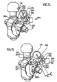
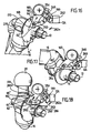
- the drive lever 190 is blocked in its pivoting movement in the direction 262a in that the driver arm 240 rests with the end face 254 on the driving surface 252 of the driving lever 250 (FIG. Fig. 16 ), which is pivoted so far by the slide track 256 that the driving surface 252 can be acted upon by the end face 254.
- the slide track 256 as in Fig. 8 illustrated, a the take-along lever 250 in the direction of the axis of rotation 202 pivoting and thus bringing into operative position, for example lifting section 256a.
- the support arm 160 is blocked against pivoting in the direction 262a, that is, in the direction of the blocking position, since the support arm rests against a side face 170 of the comb 168 and slides along it as the pivoting part rotates.
- the ball neck 16 is pivotable, for example, from the working position to a rest position.
- the pivoting of the support surface 62 'supporting end of the support arm 160 in the recess 264 serves only to allow a pivoting of the drive lever 190 in the direction 262 a by such an angle that the locking lever 272 can engage with the spherical end 274 in the recess 270.
- the support arm 160 pivots with the support surface 62 'bearing end into the recess 66' and thus passes from the release position into the blocking position, so that the support surface 62 'in turn comes in partial overlap with the contact surface 64'.
- a twisting of the eccentric portion 200 takes place such that a displacement of the support arm 160 in the direction 260a from the release position into the clamping position, so that the support surface 62 'the stop surface 64' pressurized while additionally applying the stop surface 54 on the Support surface 52 with prestressing and also without play.
- the support surfaces 62 'carrying end 162 of the support arm 160 is acted upon by a compression spring 280, which is at one end 282 on the end 162 of the support arm 160 and with another end 284 on the bearing part 10, preferably on the bearing flange 36, supported.
- this compression spring 280 With this compression spring 280, the pivoting of the support arm is completed even in no longer acting on the driving surface 252 end face 254 in the locked position and maintain the locking position until a transition from the release position to the cocking position is completed.
- the blocking position is maintained by the compression spring 280 so long until the entrainment of the clamping force generating unit 120 until the entrainment of the support arm 160 by the interaction of the nose 246 and the Mit Menuarms 240 takes place.
Landscapes
- Engineering & Computer Science (AREA)
- Transportation (AREA)
- Mechanical Engineering (AREA)
- Pivots And Pivotal Connections (AREA)
- Clamps And Clips (AREA)
- Motor Power Transmission Devices (AREA)
Claims (22)
- Attelage de remorque pour véhicules motorisés comportant une partie portante (10) disposée solidaire du véhicule et une partie pivotante (14), portée sur la partie portante (10) et comportant un col de rotule (16) et une rotule d'attelage (20) qui, par rapport à la partie portante (10), peut pivoter autour d'un axe de pivotement (12) de sorte que le col de rotule (16) peut pivoter par un mouvement de pivotement entre une position de repos et une position de travail, un serrage des éléments de butée (56, 66) de la partie pivotante (14) et des éléments supports (50, 60) de la partie portante (10) étant prévu, pour fixer le col de rotule (16) dans la position de travail, au moyen d'un mécanisme de serrage (94, 60), avec lequel au moins un des éléments supports (60) est déplaçable d'une position de non-serrage à une position de serrage et vice-versa et qu'il est possible de produire une force de serrage opérant le serrage dans la position de serrage, chacun des éléments de butée (56, 66) de la partie pivotante (14) tournant, lors du pivotement de la partie pivotante (14) autour de l'axe (12), autour de l'axe de pivotement (12) sur un chemin (65) situé à une certaine distance radiale,
l'un des éléments supports (50, 60) étant disposé sur la partie portante (10) sous forme d'un élément support (60) se déplaçant d'une position de libération dans le chemin (65) de l'élément de butée (66) correspondant à une position de verrouillage et inverse, un dispositif de manoeuvre (80) étant prévu, lequel comporte le mécanisme de serrage (94, 60), le dispositif de manoeuvre (80) faisant passer, pour fixer le col de rotule (16) dans la position de travail, l'élément support (60) de la position de libération à la position de verrouillage et une fois atteinte la position de verrouillage, le mécanisme de serrage (94, 60) faisant passer l'élément support (60) de la position de non-serrage présente dans la position de verrouillage à la position de serrage, le dispositif de manoeuvre (80) présentant un unique élément d'entraînement (82), dont la manoeuvre peut amener l'élément support mobile (60) dans chacune des positions comprenant la position de libération, la position de verrouillage, la position de non-serrage et la position de serrage,
caractérisé par le fait que le mécanisme de serrage est conçu sous forme de mécanisme à clavette (94, 60), que dans la position de serrage l'élément support (60) d'une paire (60, 66) constituée de, respectivement, l'un des éléments supports (50, 60) et d'un des éléments de butée (56, 66) agit en réajustement sur l'élément de butée (66) dans la direction de la force de serrage (58), et que le dispositif de manoeuvre (80) présente deux éléments à clavette (84, 94) pouvant être amenés l'un après l'autre dans une position agissant sur l'élément support (60), un (84) des éléments à clavette (84, 94) servant à faire passer l'élément support (60) de la position de libération dans la position de verrouillage et l'autre (94) des éléments à clavette (84, 94) servant à faire passer l'élément support (60) de la position de non-serrage dans la position de serrage. - Attelage de remorque selon la revendication 1, caractérisé par le fait que le mécanisme de serrage (94, 60) est conçu auto-bloquant.
- Attelage de remorque selon la revendication 1 ou 2, caractérisé par le fait que le mécanisme de serrage est conçu sous forme de mécanisme à clavette (94, 60).
- Attelage de remorque selon l'une quelconque des revendications précédentes, caractérisé par le fait que pour libérer le col de rotule (16), le dispositif de manoeuvre (80) fait passer le mécanisme de serrage (94, 60) de 1 position de serrage à la position de non-serrage et déplace alors l'élément support mobile (60) de la position de verrouillage dans la position de libération.
- Attelage de remorque selon l'une quelconque des revendications précédentes, caractérisé par le fait que le dispositif de manoeuvre (80) fait obligatoirement passer l'élément support mobile (60) de la position de libération à la position de verrouillage.
- Attelage de remorque selon l'une quelconque des revendications précédentes, caractérisé par le fait que le dispositif de manoeuvre (80) fait obligatoirement passer l'élément support mobile (60) de la position de non-serrage à la position de serrage.
- Attelage de remorque selon l'une quelconque des revendications précédentes, caractérisé par le fait que le dispositif de manoeuvre (80) collabore avec un organe de production d'une force de serrage (120) qui contraint avec une certaine force le dispositif de manoeuvre (80) au sens d'une manoeuvre en direction de la position de verrouillage et de la position de serrage du mécanisme de serrage (94, 60).
- Attelage de remorque selon la revendication 7, caractérisé par le fait que l'organe de production d'une force de serrage (120) présente un accumulateur de force (126) qui contraint une pièce de serrage (124) dans le sens d'une manoeuvre du dispositif de manoeuvre (80) pour atteindre la position de verrouillage et la position de serrage.
- Attelage de remorque selon la revendication 7 ou 8, caractérisé par le fait que l'organe de production d'une force de serrage (120) présente un dispositif de blocage (127, 130) qui, si l'on ne manoeuvre pas l'organe de production d'une force de serrage (120), bloque un mouvement de la pièce de serrage (124), depuis la position de verrouillage, en direction de la position de libération.
- Attelage de remorque selon la revendication 9, caractérisé par le fait que si l'on manoeuvre l'organe de production d'une force de serrage (120), le dispositif de blocage (127, 130) peut se débloquer pour permettre d'atteindre la position de libération.
- Attelage de remorque selon la revendication 9 ou 10, caractérisé par le fait que l'organe de production d'une force de serrage (120) présente un élément de service (152) avec lequel on peut tout d'abord débloquer le dispositif de blocage (127) puis agir sur le dispositif de manoeuvre (80) avec une force de déverrouillage.
- Attelage de remorque selon l'une des revendications précédentes, caractérisé par le fait que la partie pivotante (14) présente deux éléments de butée (56, 66) placés à distance l'un de l'autre, que la partie portante (10) comporte deux éléments supports (50, 60) et que pour fixer le col de rotule (16) dans la position de travail, l'un des éléments supports (60) et l'un des éléments de butée (66) collaborent au sens d'un mouvement de pivotement du col de rotule (16) dans une première orientation (58) à laquelle s'opposent l'autre (50) des éléments supports et l'autre des éléments de butée (56) et que de ce fait les éléments de butée (56, 66) et les éléments supports (50, 60) peuvent s'appuyer les uns contre les autres sans jeu.
- Attelage de remorque selon l'une des revendications précédentes, caractérisé par le fait que, pour fixer le col de rotule (16) dans la position de travail, les éléments de butée (56, 66) et les éléments supports (50, 60) peuvent être serrés les uns contre les autres dans une position de serrage.
- Attelage de remorque selon l'une des revendications précédentes, caractérisé par le fait que, dans la position de serrage, un accumulateur élastique de force de serrage (126) agit sur l'un (60) des éléments (60, 66).
- Attelage de remorque selon l'une quelconque des revendications précédentes, caractérisé par le fait que les éléments de butée (56, 66) peuvent se déplacer en tournant autour de l'axe de pivotement (12) sur différents chemins (55, 65).
- Attelage de remorque selon l'une des revendications précédentes, caractérisé par le fait qu'un premier des éléments de butée (56) est conçu sous forme d'élément solidairement disposé sur la partie pivotante (14).
- Attelage de remorque selon la revendication 16, caractérisé par le fait qu'un second des éléments de butée (66) est conçu sous forme d'élément solidairement disposé sur la partie pivotante (14).
- Attelage de remorque selon l'une des revendications précédentes, caractérisé par le fait que l'un (66) des éléments de butée (56, 66) est disposé sur une crête (68) de la partie pivotante (14).
- Attelage de remorque selon l'une des revendications précédentes, caractérisé par le fait qu'un autre (56) des éléments de butée (56, 66) est disposé sur un appendice du col de rotule (16) relié à la partie pivotante (14).
- Attelage de remorque selon l'une des revendications précédentes, caractérisé par le fait qu'un premier (50) des éléments supports (50, 60) est disposé dans une zone (42) arrière, vu selon le sens de la circulation, de la partie portante (10).
- Attelage de remorque selon l'une des revendications précédentes, caractérisé par le fait que l'élément support mobile (60) peut, par coulissement linéaire, se déplacer dans le chemin (65) de l'élément de butée correspondant (66).
- Attelage de remorque selon l'une des revendications précédentes, caractérisé par le fait que pour déplacer l'élément support (60) entre la position de libération et la position de verrouillage est prévu le dispositif de manoeuvre (80), et que le dispositif de manoeuvre (80) comporte un coin de positionnement (84) qui agit sur l'élément support (60) guidé dans un guidage (74).
Applications Claiming Priority (3)
| Application Number | Priority Date | Filing Date | Title |
|---|---|---|---|
| DE19848487A DE19848487A1 (de) | 1998-10-21 | 1998-10-21 | Anhängekupplung |
| DE19848487 | 1998-10-21 | ||
| EP99948968A EP1040020B1 (fr) | 1998-10-21 | 1999-10-07 | Accouplement de remorque |
Related Parent Applications (2)
| Application Number | Title | Priority Date | Filing Date |
|---|---|---|---|
| EP99948968A Division EP1040020B1 (fr) | 1998-10-21 | 1999-10-07 | Accouplement de remorque |
| EP99948968.5 Division | 1999-10-07 |
Publications (4)
| Publication Number | Publication Date |
|---|---|
| EP1182062A2 EP1182062A2 (fr) | 2002-02-27 |
| EP1182062A3 EP1182062A3 (fr) | 2002-05-08 |
| EP1182062B1 EP1182062B1 (fr) | 2004-10-27 |
| EP1182062B2 true EP1182062B2 (fr) | 2014-12-10 |
Family
ID=7885156
Family Applications (2)
| Application Number | Title | Priority Date | Filing Date |
|---|---|---|---|
| EP01128747.1A Expired - Lifetime EP1182062B2 (fr) | 1998-10-21 | 1999-10-07 | Attelage de remorque |
| EP99948968A Expired - Lifetime EP1040020B1 (fr) | 1998-10-21 | 1999-10-07 | Accouplement de remorque |
Family Applications After (1)
| Application Number | Title | Priority Date | Filing Date |
|---|---|---|---|
| EP99948968A Expired - Lifetime EP1040020B1 (fr) | 1998-10-21 | 1999-10-07 | Accouplement de remorque |
Country Status (4)
| Country | Link |
|---|---|
| US (1) | US6409201B1 (fr) |
| EP (2) | EP1182062B2 (fr) |
| DE (3) | DE19848487A1 (fr) |
| WO (1) | WO2000023290A1 (fr) |
Families Citing this family (33)
| Publication number | Priority date | Publication date | Assignee | Title |
|---|---|---|---|---|
| DE10017013A1 (de) * | 2000-04-05 | 2001-10-18 | Oris Fahrzeugteile Riehle H | Anhängekupplung |
| DE10023640C2 (de) * | 2000-05-13 | 2003-05-08 | Fac Frank Abels Consult & Tech | Anhängerkupplung |
| DE10104185A1 (de) * | 2001-01-23 | 2002-07-25 | Fac Frank Abels Consult & Tech | Anhängerkupplung |
| DE10134318A1 (de) * | 2001-07-14 | 2003-01-23 | Fac Frank Abels Consult & Tech | Anhängerkupplung |
| US6619686B1 (en) * | 2001-08-07 | 2003-09-16 | Jerry Edwards | Folding towbar and lock mechanism |
| DE10144254A1 (de) | 2001-09-03 | 2003-04-03 | Oris Fahrzeugteile Riehle H | Anhängekupplung |
| DE50302195D1 (de) | 2002-02-28 | 2006-04-06 | Kober Ag | Schwenkbare anhängevorrichtung für zugfahrzeuge |
| DE20215508U1 (de) * | 2002-10-09 | 2004-04-01 | Al-Ko Kober Ag | Anhängevorrichtung für Zugfahrzeuge |
| DE10231221A1 (de) * | 2002-07-11 | 2004-01-29 | Dr.Ing.H.C. F. Porsche Ag | Anhängezugvorrichtung |
| US6860503B2 (en) * | 2002-11-13 | 2005-03-01 | Westfalia-Automotive Gmbh & Co. Kg | Retractile motor-vehicle trailer hitch |
| DE10320302A1 (de) * | 2003-05-07 | 2004-12-09 | Westfalia-Automotive Gmbh & Co. Kg | Anhängekupplung für Kraftfahrzeuge |
| DE10323619B4 (de) * | 2003-05-26 | 2009-09-03 | Audi Ag | Abnehmbare Anhängevorrichtung für Fahrzeuge, insbesondere für Kraftfahrzeuge |
| DE10342834A1 (de) * | 2003-09-17 | 2005-05-04 | Westfalia Automotive Gmbh & Co | Schwenkbare Anhängekupplung |
| DE10354753B4 (de) * | 2003-11-21 | 2014-07-24 | Westfalia-Automotive Gmbh | Anhängekupplung für Kraftfahrzeuge |
| DE102004004503B4 (de) * | 2004-01-22 | 2022-01-20 | ACPS Automotive GmbH | Anhängekupplung |
| DE102004004501B4 (de) * | 2004-01-22 | 2021-07-01 | ACPS Automotive GmbH | Anhängekupplung |
| NL1026198C2 (nl) * | 2004-05-14 | 2005-11-15 | Brink Internat B V | Verdraaibare trekhaak. |
| DE102005032474A1 (de) * | 2005-07-07 | 2007-01-11 | Oris Fahrzeugteile Hans Riehle Gmbh | Anhängevorrichtung |
| US7472919B2 (en) * | 2005-07-28 | 2009-01-06 | Daimler Trucks North America Llc | Detachable tow hook assembly and vehicle with one or more detachable tow hooks |
| DE102006035261A1 (de) † | 2006-07-29 | 2008-01-31 | Scambia Industrial Developments Aktiengesellschaft | Anhängekupplung |
| DE102009033911A1 (de) * | 2009-07-20 | 2011-01-27 | Westfalia-Automotive Gmbh | Anhängekupplung |
| DE102009046931A1 (de) * | 2009-11-20 | 2011-05-26 | Zf Friedrichshafen Ag | Kugelschwenkmodul |
| EP3379222B1 (fr) | 2017-03-22 | 2020-12-30 | Methode Electronics Malta Ltd. | Ensemble de capteur à base magnétoélastique |
| EP3727901B1 (fr) | 2017-12-20 | 2025-09-24 | Horizon Global (South Africa) (Pty) Ltd | Barre de remorquage pourvue d'un système de boule d'attelage |
| US11135882B2 (en) | 2018-02-27 | 2021-10-05 | Methode Electronics, Inc. | Towing systems and methods using magnetic field sensing |
| EP3758959B1 (fr) | 2018-02-27 | 2025-11-05 | Methode Electronics, Inc. | Systèmes et procédés de remorquage utilisant la détection magnétique |
| US11491832B2 (en) | 2018-02-27 | 2022-11-08 | Methode Electronics, Inc. | Towing systems and methods using magnetic field sensing |
| US11221262B2 (en) | 2018-02-27 | 2022-01-11 | Methode Electronics, Inc. | Towing systems and methods using magnetic field sensing |
| US11084342B2 (en) | 2018-02-27 | 2021-08-10 | Methode Electronics, Inc. | Towing systems and methods using magnetic field sensing |
| CZ309084B6 (cs) | 2020-07-07 | 2022-01-19 | Brano A.S. | Výklopné tažné zařízení |
| DE112022002547A5 (de) * | 2021-07-06 | 2024-03-07 | Westfalia-Automotive Gmbh | Anhängekupplung mit Betätigungskonturen und Widerlagerkonturen |
| EP4309485B1 (fr) * | 2022-07-19 | 2025-06-11 | CNH Industrial Belgium N.V. | Élévateur intégré à l'intérieur d'un attelage de moissonneuse-batteuse |
| CN119749119B (zh) * | 2024-07-31 | 2025-11-04 | 比亚迪股份有限公司 | 拖车装置和汽车 |
Citations (11)
| Publication number | Priority date | Publication date | Assignee | Title |
|---|---|---|---|---|
| DE3328524A1 (de) † | 1983-08-06 | 1985-02-21 | Daimler-Benz Ag, 7000 Stuttgart | Anhaengerkupplung fuer fahrzeuge |
| DE8716502U1 (de) † | 1987-12-15 | 1988-02-04 | Peka-Fahrzeugbau Gmbh + Co Kg, 7500 Karlsruhe | Abnehmbare Fahrzeug-Anhängerkupplung |
| DE9105268U1 (de) † | 1991-04-29 | 1991-07-25 | Peka-Fahrzeugbau Gmbh + Co Kg, 7500 Karlsruhe | Abnehmbare Anhänger-Kupplung |
| DE4312208A1 (de) † | 1993-04-14 | 1994-10-20 | Westfalia Werke Knoebel | Kupplungskugelträger für Fahrzeug-Anhängerkupplungen |
| DE4413985C1 (de) † | 1994-04-21 | 1995-09-21 | Oris Fahrzeugteile Riehle H | Abnehmbare Anhängerkupplung für Fahrzeuge, insbesondere Personenkraftwagen |
| DE19521896A1 (de) † | 1995-06-16 | 1997-01-30 | Oris Fahrzeugteile Riehle H | Anhängevorrichtung für insbesondere Personenkraftwagen |
| DE19612962A1 (de) † | 1996-04-01 | 1997-10-02 | Oris Fahrzeugteile Riehle H | Anhängekupplung |
| WO1997036760A1 (fr) † | 1996-04-01 | 1997-10-09 | Oris Fahrzeugteile Hans Riehle Gmbh | Accouplement de remorque |
| DE19605570C2 (de) † | 1995-09-13 | 1997-11-13 | Cartron Fahrzeugteile Gmbh | Axial verstellbare Anhängerkupplung für Kraftfahrzeuge |
| DE19651562A1 (de) † | 1996-12-11 | 1998-06-18 | Peter Rocca | Anhängekupplung |
| DE69714939T2 (de) † | 1996-10-01 | 2003-04-24 | Safenat Paneach N.V., Willemstad | Abnehmbare Anhängerkupplung |
Family Cites Families (15)
| Publication number | Priority date | Publication date | Assignee | Title |
|---|---|---|---|---|
| US2733936A (en) * | 1956-02-07 | Retractible trailer hitch | ||
| FR2227739A5 (en) * | 1973-04-25 | 1974-11-22 | Gumuchian Pierre | Retracting drawgear for road type trailers - can be housed under trailer chassis when not in use |
| SE390144B (sv) * | 1975-05-06 | 1976-12-06 | Volvo Ab | Draganordning fos motorfordon |
| SE390143B (sv) * | 1975-05-06 | 1976-12-06 | Volvo Ab | Draganordning ffor motorfordon |
| FR2450167A1 (fr) * | 1979-02-27 | 1980-09-26 | Oppermann Rene | Dispositif d'attelage escamotable pour remorque |
| US4379569A (en) * | 1981-07-30 | 1983-04-12 | Koch Richard L | Trailer hitch adaptor |
| FR2614242B1 (fr) * | 1987-04-24 | 1989-07-21 | Peugeot | Dispositif de fixation d'un crochet de remorquage sur un vehicule automobile. |
| DE3810164A1 (de) * | 1988-03-25 | 1989-10-05 | Porsche Ag | Anhaengevorrichtung fuer fahrzeuge |
| FR2647394B1 (fr) * | 1989-05-24 | 1991-08-16 | Wiart Autier | Dispositif d'attelage a boule escamotable pour vehicules automobiles |
| SE466954B (sv) * | 1990-03-30 | 1992-05-04 | Stefan Andersson | Draganordning vid fordon |
| DE9109699U1 (de) * | 1991-08-06 | 1992-01-16 | Prieschl, Herbert, 7117 Bretzfeld | Anhängekupplung für PKW's |
| DE29520254U1 (de) * | 1995-09-13 | 1996-04-11 | Cartron Fahrzeugteile GmbH, 27367 Sottrum | Anhängerkupplung für Kraftfahrzeuge |
| DE19654867C2 (de) * | 1995-09-13 | 1998-01-22 | Cartron Fahrzeugteile Gmbh | Schwenkbare Anhängerkupplung für Kraftfahrzeuge |
| DE19612959A1 (de) * | 1996-04-01 | 1997-10-02 | Oris Fahrzeugteile Riehle H | Anhängekupplung |
| DE19613428A1 (de) * | 1996-04-04 | 1997-10-09 | Oris Fahrzeugteile Riehle H | Anhängevorrichtung für die Anordnung an insbesondere Personenkraftwagen |
-
1998
- 1998-10-21 DE DE19848487A patent/DE19848487A1/de not_active Ceased
-
1999
- 1999-10-07 EP EP01128747.1A patent/EP1182062B2/fr not_active Expired - Lifetime
- 1999-10-07 WO PCT/EP1999/007541 patent/WO2000023290A1/fr not_active Ceased
- 1999-10-07 DE DE59902547T patent/DE59902547D1/de not_active Expired - Lifetime
- 1999-10-07 EP EP99948968A patent/EP1040020B1/fr not_active Expired - Lifetime
- 1999-10-07 DE DE59910955T patent/DE59910955D1/de not_active Expired - Lifetime
-
2000
- 2000-06-21 US US09/598,737 patent/US6409201B1/en not_active Expired - Lifetime
Patent Citations (11)
| Publication number | Priority date | Publication date | Assignee | Title |
|---|---|---|---|---|
| DE3328524A1 (de) † | 1983-08-06 | 1985-02-21 | Daimler-Benz Ag, 7000 Stuttgart | Anhaengerkupplung fuer fahrzeuge |
| DE8716502U1 (de) † | 1987-12-15 | 1988-02-04 | Peka-Fahrzeugbau Gmbh + Co Kg, 7500 Karlsruhe | Abnehmbare Fahrzeug-Anhängerkupplung |
| DE9105268U1 (de) † | 1991-04-29 | 1991-07-25 | Peka-Fahrzeugbau Gmbh + Co Kg, 7500 Karlsruhe | Abnehmbare Anhänger-Kupplung |
| DE4312208A1 (de) † | 1993-04-14 | 1994-10-20 | Westfalia Werke Knoebel | Kupplungskugelträger für Fahrzeug-Anhängerkupplungen |
| DE4413985C1 (de) † | 1994-04-21 | 1995-09-21 | Oris Fahrzeugteile Riehle H | Abnehmbare Anhängerkupplung für Fahrzeuge, insbesondere Personenkraftwagen |
| DE19521896A1 (de) † | 1995-06-16 | 1997-01-30 | Oris Fahrzeugteile Riehle H | Anhängevorrichtung für insbesondere Personenkraftwagen |
| DE19605570C2 (de) † | 1995-09-13 | 1997-11-13 | Cartron Fahrzeugteile Gmbh | Axial verstellbare Anhängerkupplung für Kraftfahrzeuge |
| DE19612962A1 (de) † | 1996-04-01 | 1997-10-02 | Oris Fahrzeugteile Riehle H | Anhängekupplung |
| WO1997036760A1 (fr) † | 1996-04-01 | 1997-10-09 | Oris Fahrzeugteile Hans Riehle Gmbh | Accouplement de remorque |
| DE69714939T2 (de) † | 1996-10-01 | 2003-04-24 | Safenat Paneach N.V., Willemstad | Abnehmbare Anhängerkupplung |
| DE19651562A1 (de) † | 1996-12-11 | 1998-06-18 | Peter Rocca | Anhängekupplung |
Also Published As
| Publication number | Publication date |
|---|---|
| DE19848487A1 (de) | 2000-05-04 |
| WO2000023290A1 (fr) | 2000-04-27 |
| DE59910955D1 (de) | 2004-12-02 |
| EP1182062B1 (fr) | 2004-10-27 |
| EP1182062A2 (fr) | 2002-02-27 |
| EP1182062A3 (fr) | 2002-05-08 |
| DE59902547D1 (de) | 2002-10-10 |
| US6409201B1 (en) | 2002-06-25 |
| EP1040020A1 (fr) | 2000-10-04 |
| EP1040020B1 (fr) | 2002-09-04 |
Similar Documents
| Publication | Publication Date | Title |
|---|---|---|
| EP1182062B2 (fr) | Attelage de remorque | |
| EP1024036B1 (fr) | Attelage de remorque | |
| EP1557298B2 (fr) | Attelage de remorque | |
| DE3922316B4 (de) | Neigungseinstellvorrichtung für die Rückenlehne von Sitzen | |
| EP1621386B1 (fr) | Dispositif pare-vent | |
| DE10144254A1 (de) | Anhängekupplung | |
| DE4005369C2 (de) | Schließeinrichtung an einer Fahrzeugtür | |
| DE2901192A1 (de) | Halterung fuer ein einstellbares lenkhandrad fuer kraftfahrzeuge | |
| EP3911553B1 (fr) | Colonne de direction pour un véhicule automobile | |
| BE1030669B1 (de) | Lenksäule für ein Kraftfahrzeug | |
| EP0326570A1 (fr) | Barre d'attelage reglable en hauteur pour remorque de vehicule. | |
| EP1783001B1 (fr) | Galerie de toit | |
| WO2022008428A1 (fr) | Colonne de direction pour véhicule automobile | |
| EP0913276B1 (fr) | Dispositif d'attelage | |
| DE68903996T2 (de) | Steife und loesbare verbindungsstelle. | |
| EP1338453B1 (fr) | Dispositif de verrouillage et centrage pour un toit de véhicule ouvrant | |
| DE4030095C2 (fr) | ||
| DE1277035B (de) | Kraftfahrzeugkupplung fuer Sattelschlepper | |
| DE10209811A1 (de) | Cabriolet-Fahrzeug mit Verdeckklappe und mit dieser koppelbarem Überrollbügel | |
| EP0889791B1 (fr) | Dispositif tracte | |
| DE8510957U1 (de) | Höhenverstellbare Anhängevorrichtung | |
| DE3513367A1 (de) | Hoehenverstellbare anhaengevorrichtung | |
| EP2796305A1 (fr) | Attelage | |
| DE102009015049A1 (de) | Innenbackenbremse mit automatischer Nachstellung des Bremsbackenlüftspiels | |
| EP0393216A1 (fr) | Crochet d'attelage |
Legal Events
| Date | Code | Title | Description |
|---|---|---|---|
| PUAI | Public reference made under article 153(3) epc to a published international application that has entered the european phase |
Free format text: ORIGINAL CODE: 0009012 |
|
| AC | Divisional application: reference to earlier application |
Ref document number: 1040020 Country of ref document: EP |
|
| AK | Designated contracting states |
Kind code of ref document: A2 Designated state(s): DE FR GB |
|
| PUAL | Search report despatched |
Free format text: ORIGINAL CODE: 0009013 |
|
| RIN1 | Information on inventor provided before grant (corrected) |
Inventor name: RIEHLE, HANS |
|
| AK | Designated contracting states |
Kind code of ref document: A3 Designated state(s): DE FR GB |
|
| 17P | Request for examination filed |
Effective date: 20020629 |
|
| AKX | Designation fees paid |
Designated state(s): DE FR GB |
|
| 17Q | First examination report despatched |
Effective date: 20030407 |
|
| GRAP | Despatch of communication of intention to grant a patent |
Free format text: ORIGINAL CODE: EPIDOSNIGR1 |
|
| GRAS | Grant fee paid |
Free format text: ORIGINAL CODE: EPIDOSNIGR3 |
|
| GRAA | (expected) grant |
Free format text: ORIGINAL CODE: 0009210 |
|
| AC | Divisional application: reference to earlier application |
Ref document number: 1040020 Country of ref document: EP Kind code of ref document: P |
|
| AK | Designated contracting states |
Kind code of ref document: B1 Designated state(s): DE FR GB |
|
| REG | Reference to a national code |
Ref country code: GB Ref legal event code: FG4D Free format text: NOT ENGLISH |
|
| REF | Corresponds to: |
Ref document number: 59910955 Country of ref document: DE Date of ref document: 20041202 Kind code of ref document: P |
|
| PLBI | Opposition filed |
Free format text: ORIGINAL CODE: 0009260 |
|
| PLAX | Notice of opposition and request to file observation + time limit sent |
Free format text: ORIGINAL CODE: EPIDOSNOBS2 |
|
| ET | Fr: translation filed | ||
| 26 | Opposition filed |
Opponent name: WESTFALIA-AUTOMOTIVE GMBH & CO. KG Effective date: 20050719 |
|
| PGFP | Annual fee paid to national office [announced via postgrant information from national office to epo] |
Ref country code: GB Payment date: 20051005 Year of fee payment: 7 |
|
| PLAF | Information modified related to communication of a notice of opposition and request to file observations + time limit |
Free format text: ORIGINAL CODE: EPIDOSCOBS2 |
|
| PLAF | Information modified related to communication of a notice of opposition and request to file observations + time limit |
Free format text: ORIGINAL CODE: EPIDOSCOBS2 |
|
| PLAF | Information modified related to communication of a notice of opposition and request to file observations + time limit |
Free format text: ORIGINAL CODE: EPIDOSCOBS2 |
|
| PLBB | Reply of patent proprietor to notice(s) of opposition received |
Free format text: ORIGINAL CODE: EPIDOSNOBS3 |
|
| RAP2 | Party data changed (patent owner data changed or rights of a patent transferred) |
Owner name: SCAMBIA INDUSTRIAL DEVELOPMENTS AKTIENGESELLSCHAFT |
|
| PLAB | Opposition data, opponent's data or that of the opponent's representative modified |
Free format text: ORIGINAL CODE: 0009299OPPO |
|
| R26 | Opposition filed (corrected) |
Opponent name: WESTFALIA-AUTOMOTIVE GMBH Effective date: 20050719 |
|
| RDAF | Communication despatched that patent is revoked |
Free format text: ORIGINAL CODE: EPIDOSNREV1 |
|
| APAH | Appeal reference modified |
Free format text: ORIGINAL CODE: EPIDOSCREFNO |
|
| APBP | Date of receipt of notice of appeal recorded |
Free format text: ORIGINAL CODE: EPIDOSNNOA2O |
|
| GBPC | Gb: european patent ceased through non-payment of renewal fee |
Effective date: 20061007 |
|
| APBQ | Date of receipt of statement of grounds of appeal recorded |
Free format text: ORIGINAL CODE: EPIDOSNNOA3O |
|
| PG25 | Lapsed in a contracting state [announced via postgrant information from national office to epo] |
Ref country code: GB Free format text: LAPSE BECAUSE OF NON-PAYMENT OF DUE FEES Effective date: 20061007 |
|
| REG | Reference to a national code |
Ref country code: FR Ref legal event code: TP |
|
| REG | Reference to a national code |
Ref country code: FR Ref legal event code: ST Effective date: 20080630 |
|
| PGFP | Annual fee paid to national office [announced via postgrant information from national office to epo] |
Ref country code: FR Payment date: 20061011 Year of fee payment: 8 |
|
| PG25 | Lapsed in a contracting state [announced via postgrant information from national office to epo] |
Ref country code: FR Free format text: LAPSE BECAUSE OF NON-PAYMENT OF DUE FEES Effective date: 20071031 |
|
| APBU | Appeal procedure closed |
Free format text: ORIGINAL CODE: EPIDOSNNOA9O |
|
| PLAY | Examination report in opposition despatched + time limit |
Free format text: ORIGINAL CODE: EPIDOSNORE2 |
|
| PLAH | Information related to despatch of examination report in opposition + time limit modified |
Free format text: ORIGINAL CODE: EPIDOSCORE2 |
|
| PLBC | Reply to examination report in opposition received |
Free format text: ORIGINAL CODE: EPIDOSNORE3 |
|
| APBM | Appeal reference recorded |
Free format text: ORIGINAL CODE: EPIDOSNREFNO |
|
| APBP | Date of receipt of notice of appeal recorded |
Free format text: ORIGINAL CODE: EPIDOSNNOA2O |
|
| APAH | Appeal reference modified |
Free format text: ORIGINAL CODE: EPIDOSCREFNO |
|
| APBQ | Date of receipt of statement of grounds of appeal recorded |
Free format text: ORIGINAL CODE: EPIDOSNNOA3O |
|
| APBU | Appeal procedure closed |
Free format text: ORIGINAL CODE: EPIDOSNNOA9O |
|
| PLAB | Opposition data, opponent's data or that of the opponent's representative modified |
Free format text: ORIGINAL CODE: 0009299OPPO |
|
| R26 | Opposition filed (corrected) |
Opponent name: WESTFALIA-AUTOMOTIVE GMBH Effective date: 20050719 |
|
| PUAH | Patent maintained in amended form |
Free format text: ORIGINAL CODE: 0009272 |
|
| STAA | Information on the status of an ep patent application or granted ep patent |
Free format text: STATUS: PATENT MAINTAINED AS AMENDED |
|
| 27A | Patent maintained in amended form |
Effective date: 20141210 |
|
| AK | Designated contracting states |
Kind code of ref document: B2 Designated state(s): DE FR GB |
|
| REG | Reference to a national code |
Ref country code: DE Ref legal event code: R102 Ref document number: 59910955 Country of ref document: DE |
|
| REG | Reference to a national code |
Ref country code: DE Ref legal event code: R102 Ref document number: 59910955 Country of ref document: DE Effective date: 20141210 |
|
| REG | Reference to a national code |
Ref country code: DE Ref legal event code: R082 Ref document number: 59910955 Country of ref document: DE Representative=s name: HOEGER, STELLRECHT & PARTNER PATENTANWAELTE, DE |
|
| REG | Reference to a national code |
Ref country code: DE Ref legal event code: R082 Ref document number: 59910955 Country of ref document: DE Representative=s name: HOEGER, STELLRECHT & PARTNER PATENTANWAELTE, DE Effective date: 20150407 Ref country code: DE Ref legal event code: R081 Ref document number: 59910955 Country of ref document: DE Owner name: SCAMBIA HOLDINGS CYPRUS LTD., CY Free format text: FORMER OWNER: SCAMBIA INDUSTRIAL DEVELOPMENTS AKTIENGESELLSCHAFT, SCHAAN, LI Effective date: 20150407 Ref country code: DE Ref legal event code: R082 Ref document number: 59910955 Country of ref document: DE Representative=s name: HOEGER, STELLRECHT & PARTNER PATENTANWAELTE MB, DE Effective date: 20150407 Ref country code: DE Ref legal event code: R081 Ref document number: 59910955 Country of ref document: DE Owner name: BOSAL ACPS HOLDING 2 B.V., NL Free format text: FORMER OWNER: SCAMBIA INDUSTRIAL DEVELOPMENTS AKTIENGESELLSCHAFT, SCHAAN, LI Effective date: 20150407 |
|
| REG | Reference to a national code |
Ref country code: DE Ref legal event code: R082 Ref document number: 59910955 Country of ref document: DE Representative=s name: HOEGER, STELLRECHT & PARTNER PATENTANWAELTE MB, DE |
|
| REG | Reference to a national code |
Ref country code: DE Ref legal event code: R082 Ref document number: 59910955 Country of ref document: DE Representative=s name: HOEGER, STELLRECHT & PARTNER PATENTANWAELTE MB, DE Ref country code: DE Ref legal event code: R081 Ref document number: 59910955 Country of ref document: DE Owner name: BOSAL ACPS HOLDING 2 B.V., NL Free format text: FORMER OWNER: SCAMBIA HOLDINGS CYPRUS LTD., LIMASSOL, CY |
|
| PGFP | Annual fee paid to national office [announced via postgrant information from national office to epo] |
Ref country code: DE Payment date: 20171019 Year of fee payment: 19 |
|
| REG | Reference to a national code |
Ref country code: DE Ref legal event code: R119 Ref document number: 59910955 Country of ref document: DE |
|
| PG25 | Lapsed in a contracting state [announced via postgrant information from national office to epo] |
Ref country code: DE Free format text: LAPSE BECAUSE OF NON-PAYMENT OF DUE FEES Effective date: 20190501 |