EP1182103A2 - Dispositif de verrouillage pour la colonne de direction d'un véhicule - Google Patents
Dispositif de verrouillage pour la colonne de direction d'un véhicule Download PDFInfo
- Publication number
- EP1182103A2 EP1182103A2 EP01202994A EP01202994A EP1182103A2 EP 1182103 A2 EP1182103 A2 EP 1182103A2 EP 01202994 A EP01202994 A EP 01202994A EP 01202994 A EP01202994 A EP 01202994A EP 1182103 A2 EP1182103 A2 EP 1182103A2
- Authority
- EP
- European Patent Office
- Prior art keywords
- locking
- driver
- spring
- locking pin
- control cam
- Prior art date
- Legal status (The legal status is an assumption and is not a legal conclusion. Google has not performed a legal analysis and makes no representation as to the accuracy of the status listed.)
- Granted
Links
- 238000006073 displacement reaction Methods 0.000 claims description 7
- 229910000831 Steel Inorganic materials 0.000 description 1
- 210000003746 feather Anatomy 0.000 description 1
- 230000005764 inhibitory process Effects 0.000 description 1
- 230000002040 relaxant effect Effects 0.000 description 1
- 239000010959 steel Substances 0.000 description 1
Images

Classifications
-
- B—PERFORMING OPERATIONS; TRANSPORTING
- B60—VEHICLES IN GENERAL
- B60R—VEHICLES, VEHICLE FITTINGS, OR VEHICLE PARTS, NOT OTHERWISE PROVIDED FOR
- B60R25/00—Fittings or systems for preventing or indicating unauthorised use or theft of vehicles
- B60R25/01—Fittings or systems for preventing or indicating unauthorised use or theft of vehicles operating on vehicle systems or fittings, e.g. on doors, seats or windscreens
- B60R25/02—Fittings or systems for preventing or indicating unauthorised use or theft of vehicles operating on vehicle systems or fittings, e.g. on doors, seats or windscreens operating on the steering mechanism
- B60R25/021—Fittings or systems for preventing or indicating unauthorised use or theft of vehicles operating on vehicle systems or fittings, e.g. on doors, seats or windscreens operating on the steering mechanism restraining movement of the steering column or steering wheel hub, e.g. restraining means controlled by ignition switch
- B60R25/0215—Fittings or systems for preventing or indicating unauthorised use or theft of vehicles operating on vehicle systems or fittings, e.g. on doors, seats or windscreens operating on the steering mechanism restraining movement of the steering column or steering wheel hub, e.g. restraining means controlled by ignition switch using electric means, e.g. electric motors or solenoids
- B60R25/02153—Fittings or systems for preventing or indicating unauthorised use or theft of vehicles operating on vehicle systems or fittings, e.g. on doors, seats or windscreens operating on the steering mechanism restraining movement of the steering column or steering wheel hub, e.g. restraining means controlled by ignition switch using electric means, e.g. electric motors or solenoids comprising a locking member radially and linearly moved towards the steering column
Definitions
- the invention relates to a device for locking the steering spindle of a steering device of a motor vehicle.
- Such a device is known for example from DE 196 53 860 C1.
- This known device comprises both one in the direction of its longitudinal axis In a locking position and vice versa sliding locking pin as well one designed as an eccentric and rotatably arranged by an electric motor Control cam, which causes the locking bolt to move as it rotates.
- the control cam is supported directly on its side facing away from the steering spindle from a contact surface of a relatively large central cutout of the locking bolt.
- the locking pin does not get into its locking position because it is on the above web or tooth-shaped area between two locking grooves one on the steering spindle attached locking ring hits (ready-to-lock position), so the rotates Control cam until it reaches its end position, but the locking pin remains initially in its position on the protruding area of the locking ring, and so long until the locking bolt is turned by the preloaded spring by turning the steering spindle is pressed into one of the adjacent locking grooves.
- this known device has, inter alia, the disadvantage that the for the shift the locking pin in its locking position responsible spring in the Unlocking position is constantly biased and therefore after a certain time Spring fatigue can occur, which is what vehicle manufacturers demand after a secure locking of the steering spindle, if possible, during the entire service life of the corresponding vehicle.
- the invention has for its object a device of the aforementioned Specify type that is simple and space-saving and with a safe movement of the locking bolt in its locking position even after a longer period Period is guaranteed.
- the invention is essentially based on the idea of moving the locking pin from the un- to the locked position not a pre-stressed, at the Movement of the locking bolt to pull the relaxing spring, but an elastic (spring-loaded) driver, which has a contact surface on which the control cam is supported on its side facing the steering spindle. Is located the locking pin in its unlocked position, the contact surface of the driver on the control cam without the spring needing to be significantly tensioned. at rotation of the control cam then becomes the driver and over the relatively stiff Spring also moved the locking pin axially. There is usually no tension the spring. Only if the locking pin is not in its locking position arrives because e.g.
- the locking pin does not have a central cutout, but on it the side facing away from the steering spindle with a laterally projecting leg is, the surface facing the steering spindle is the contact surface of the control cam forms.
- a body extending in the direction of the longitudinal axis of the locking bolt has, on the opposite sides in each case at least one laterally protruding Arm is arranged, wherein the control cam is supported on the first arm and the second arm engages in a first longitudinal groove of the locking pin, in which the spring is arranged on the one hand on the second arm of the driver and on the other hand, is supported on the end of the longitudinal groove facing the steering spindle.
- the body of the driver is within one second longitudinal groove of the locking bolt slidably arranged, said longitudinal groove has on its side facing the steering shaft a stop that the displacement of the driver limited in an inhibition of the locking pin, if the latter is moved into its locking position.
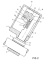
- 1 denotes a steering spindle of a motor vehicle on which a locking ring 2 fastened with locking grooves 3 and a device 4 according to the invention is arranged to lock the steering shaft.
- the device 4 comprises a housing 5, in which both one in the direction of its longitudinal axis 6 slidable, e.g. made of steel locking pin 7 as well as an eccentric trained and rotatable about an axis of rotation 8 control cam 9 arranged are.
- the locking pin 7 has on its side facing away from the steering spindle 1 a laterally protruding leg 10, on the one facing the steering shaft 1 Surface (contact surface) 11 of the control cam 9 is supported.
- the control cam 9 On its side facing the steering shaft 1, the control cam 9 is supported on the Contact surface 12 of e.g. plastic driver 13 from the direction the longitudinal axis 6 of the locking pin 7 slidably mounted in the housing 5 and is connected to the locking pin 7 via a relatively rigid spring 14. There is the driver 13 from a extending in the direction of the longitudinal axis 6 of the locking pin 7 Body 15, on each of which a laterally protruding on opposite sides Arm 16, 17 is arranged.
- the control cam is supported on the first arm 16 9 from.
- the second arm 17 engages in a first longitudinal groove 18 of the locking bolt 7, in which the spring 14 is arranged.
- the latter is supported with its first end the second arm 17 of the driver 13 and with its second end on that of the steering spindle 1 facing end 19 of the first longitudinal groove 18.
- a second longitudinal groove 20 is also provided, along which the body 15 of the driver 13 is slidably disposed, the longitudinal groove 20 has on its side facing the steering shaft 1 a stop 21 which the Limited displacement of the driver 13 when the locking bolt 7 is inhibited, when it is moved to its locked position.
- the mode of operation of the device according to the invention is discussed below. It is assumed that device 4 is shown in FIG Locked position. If the device 4 is to be unlocked, then e.g. by actuating a key (not shown) of the control cam 9 rotating electric motor activated. The control cam 9 then turns e.g. clockwise about its axis of rotation 8. The leg 10 of the locking bolt 7 is after pressed above and its lower end 22 is pulled out of the locking groove 3. The locking pin 7 takes the one pressed by the spring 14 into a fixing groove 23 of the locking bolt 7 Driver 13 with.
- the switches Electric motor from so that the control cam 9 does not turn further and a not shown
- the locking pin fixes the locking pin 7 on the housing 5.
- the ignition key can then be turned to the start position to start the vehicle.
- the locking pin is to be moved from the unlocked position to the locked position, e.g. by turning back the ignition key, first the safety bolt (not shown) withdrawn and then driving the control cam 9 Electric motor activated.
- the control cam 9 rotates, it now presses against the contact surface 12 of the driver 13 and thereby shifts both the driver 13 and, via the relatively stiff spring 14, also the locking pin 7.
- the stiffness the spring is chosen such that there is no significant tensioning of the spring, when the locking pin 7 is moved into a locking groove 3 of the locking ring 2 (Fig.1).
- the control cam 9 continues to rotate until it has reached its end position. simultaneously the driver 13 is moved against the pressure of the spring 14 until the body 15 of the driver has reached the stop 21. This makes the spring 14 corresponding biased.
Landscapes
- Engineering & Computer Science (AREA)
- Mechanical Engineering (AREA)
- Lock And Its Accessories (AREA)
Applications Claiming Priority (2)
| Application Number | Priority Date | Filing Date | Title |
|---|---|---|---|
| DE10041018A DE10041018A1 (de) | 2000-08-22 | 2000-08-22 | Vorrichtung zur Verriegelung der Lenkspindel eines Kraftfahrzeuges |
| DE10041018 | 2000-08-22 |
Publications (3)
| Publication Number | Publication Date |
|---|---|
| EP1182103A2 true EP1182103A2 (fr) | 2002-02-27 |
| EP1182103A3 EP1182103A3 (fr) | 2004-01-28 |
| EP1182103B1 EP1182103B1 (fr) | 2005-04-13 |
Family
ID=7653274
Family Applications (1)
| Application Number | Title | Priority Date | Filing Date |
|---|---|---|---|
| EP01202994A Expired - Lifetime EP1182103B1 (fr) | 2000-08-22 | 2001-08-08 | Dispositif de verrouillage pour la colonne de direction d'un véhicule |
Country Status (3)
| Country | Link |
|---|---|
| EP (1) | EP1182103B1 (fr) |
| DE (2) | DE10041018A1 (fr) |
| ES (1) | ES2240327T3 (fr) |
Cited By (3)
| Publication number | Priority date | Publication date | Assignee | Title |
|---|---|---|---|---|
| EP1600343A1 (fr) * | 2004-05-24 | 2005-11-30 | Alpha Corporation | Verrou de direction électrique |
| US9457833B2 (en) | 2010-01-27 | 2016-10-04 | Strattec Security Corporation | Steering lock |
| US9731681B2 (en) | 2014-04-29 | 2017-08-15 | Strattec Security Corporation | Steering lock |
Families Citing this family (1)
| Publication number | Priority date | Publication date | Assignee | Title |
|---|---|---|---|---|
| DE102004053438A1 (de) | 2004-11-05 | 2006-05-11 | Valeo Sicherheitssysteme Gmbh | Lenkschloß |
Family Cites Families (11)
| Publication number | Priority date | Publication date | Assignee | Title |
|---|---|---|---|---|
| DE737645C (de) * | 1934-06-21 | 1943-07-17 | Abram Neiman | Sicherungsvorrichtung gegen Diebstahl von Fahrzeugen, insbesondere Kraftfahrzeugen |
| DE2030564A1 (de) * | 1970-06-20 | 1971-12-30 | Daimler-Benz Ag, 7000 Stuttgart | Lenkschloß für Kraftfahrzeuge |
| DE3443712A1 (de) * | 1984-11-30 | 1986-06-05 | Hülsbeck & Fürst GmbH & Co KG, 5620 Velbert | Lenk- und zuendschloss fuer kraftfahrzeuge |
| DE3611483C1 (en) * | 1986-04-05 | 1987-09-17 | Daimler Benz Ag | Steering lock for motor vehicles |
| DE3611962A1 (de) * | 1986-04-09 | 1987-10-15 | Tibbe Kg | Kraftfahrzeug-lenkschloss |
| DE3622361A1 (de) * | 1986-07-03 | 1988-01-14 | Daimler Benz Ag | Entsperrsicherung fuer eine lenkradverriegelung |
| DE3626925A1 (de) * | 1986-08-08 | 1988-02-18 | Daimler Benz Ag | Lenkradverriegelung fuer kraftwagen |
| IT208339Z2 (it) * | 1986-11-04 | 1988-05-28 | Turatti Mario | Dispositivo antifurto bloccasterzo per autoveicoli |
| JP2530045Y2 (ja) * | 1990-11-09 | 1997-03-26 | 株式会社東海理化電機製作所 | ステアリングロック装置 |
| DE19653860C1 (de) * | 1996-12-21 | 1998-02-26 | Valeo Gmbh & Co Schliessyst Kg | Schließsystem für Kraftfahrzeuge |
| EP1386798B1 (fr) * | 1997-03-28 | 2005-10-26 | HONDA LOCK MFG. Co., LTD. | Dispositif de verrouillage de direction |
-
2000
- 2000-08-22 DE DE10041018A patent/DE10041018A1/de not_active Withdrawn
-
2001
- 2001-08-08 EP EP01202994A patent/EP1182103B1/fr not_active Expired - Lifetime
- 2001-08-08 DE DE50105891T patent/DE50105891D1/de not_active Expired - Lifetime
- 2001-08-08 ES ES01202994T patent/ES2240327T3/es not_active Expired - Lifetime
Non-Patent Citations (1)
| Title |
|---|
| None |
Cited By (5)
| Publication number | Priority date | Publication date | Assignee | Title |
|---|---|---|---|---|
| EP1600343A1 (fr) * | 2004-05-24 | 2005-11-30 | Alpha Corporation | Verrou de direction électrique |
| CN100493965C (zh) * | 2004-05-24 | 2009-06-03 | 株式会社阿尔发 | 电动转向锁紧装置 |
| US7975516B2 (en) | 2004-05-24 | 2011-07-12 | Alpha Corporation | Electric steering lock apparatus |
| US9457833B2 (en) | 2010-01-27 | 2016-10-04 | Strattec Security Corporation | Steering lock |
| US9731681B2 (en) | 2014-04-29 | 2017-08-15 | Strattec Security Corporation | Steering lock |
Also Published As
| Publication number | Publication date |
|---|---|
| EP1182103A3 (fr) | 2004-01-28 |
| DE50105891D1 (de) | 2005-05-19 |
| DE10041018A1 (de) | 2002-03-07 |
| ES2240327T3 (es) | 2005-10-16 |
| EP1182103B1 (fr) | 2005-04-13 |
Similar Documents
| Publication | Publication Date | Title |
|---|---|---|
| EP1110828B1 (fr) | Dispositif de verrouillage | |
| DE19964173C2 (de) | Vorrichtung zur elektrischen Verriegelung der Lenkspindel einer Lenkeinrichtung | |
| EP1807289B2 (fr) | Antivol de direction | |
| EP1447286A1 (fr) | Dispositif de verrouillage pour la colonne de direction d'un vehicule | |
| EP1179459A2 (fr) | Verrou de direction | |
| DE10133408A1 (de) | Verriegelungseinrichtung, insbesondere für ein Kraftfahrzeug | |
| DE10103182A1 (de) | Verriegelungsvorrichtung | |
| EP0846602B1 (fr) | Dispositif de commande pour au moins un verrou de blockage et son utilisation dans un antivol de direction pour automobile | |
| EP0912386A1 (fr) | Dispositif de verrouillage d'une colonne de direction reglable, notamment pour vehicules a moteur | |
| EP4080102B1 (fr) | Interrupteur de sécurité à gâchette | |
| DE102007059710B4 (de) | Kompakte Verriegelungsvorrichtung mit Sicherungselement | |
| DE19957624C2 (de) | Elektronisches Lenkschloß und elektronischer Zündanlaßschalter für Kraftfahrzeuge | |
| DE2757544C3 (de) | Lenkschloß für Kraftfahrzeuge | |
| EP1182103B1 (fr) | Dispositif de verrouillage pour la colonne de direction d'un véhicule | |
| DE19957546C2 (de) | Lenkschloß für Kraftfahrzeuge | |
| EP0721869A1 (fr) | Dispositif de verrouillage pour véhicules | |
| DE102009021998A1 (de) | Vorrichtung zur Ansteuerung eines Sperrgliedes | |
| DE19906268A1 (de) | Vorrichtung zur elektrischen Verriegelung der Lenkspindel einer Lenkeinrichtung | |
| DE2549774C2 (de) | Lenk- und Zündschloß | |
| DE19509097C1 (de) | Verriegelungsvorrichtung für Kraftfahrzeuge | |
| DE2252473A1 (de) | Lenk- und zuendschloss, insbesondere fuer kraftfahrzeuge | |
| DE102017214541B4 (de) | Lenksystem für ein Kraftfahrzeug | |
| DE4416864C1 (de) | Vorrichtung mit einem Wählhebel für Kraftfahrzeug-Automatikgetriebe | |
| DE1913412B2 (de) | Lenk- und zuendschloss fuer fahrzeuge | |
| EP1342632B1 (fr) | Bloquage de stationnement d'un véhichule avec transmission automatique |
Legal Events
| Date | Code | Title | Description |
|---|---|---|---|
| PUAI | Public reference made under article 153(3) epc to a published international application that has entered the european phase |
Free format text: ORIGINAL CODE: 0009012 |
|
| AK | Designated contracting states |
Kind code of ref document: A2 Designated state(s): AT BE CH CY DE DK ES FI FR GB GR IE IT LI LU MC NL PT SE TR |
|
| AX | Request for extension of the european patent |
Free format text: AL;LT;LV;MK;RO;SI |
|
| PUAL | Search report despatched |
Free format text: ORIGINAL CODE: 0009013 |
|
| AK | Designated contracting states |
Kind code of ref document: A3 Designated state(s): AT BE CH CY DE DK ES FI FR GB GR IE IT LI LU MC NL PT SE TR |
|
| AX | Request for extension of the european patent |
Extension state: AL LT LV MK RO SI |
|
| GRAP | Despatch of communication of intention to grant a patent |
Free format text: ORIGINAL CODE: EPIDOSNIGR1 |
|
| 17P | Request for examination filed |
Effective date: 20040728 |
|
| AKX | Designation fees paid |
Designated state(s): DE ES FR GB IT |
|
| RAP1 | Party data changed (applicant data changed or rights of an application transferred) |
Owner name: VALEO SICHERHEITSSYSTEME GMBH |
|
| GRAA | (expected) grant |
Free format text: ORIGINAL CODE: 0009210 |
|
| GRAS | Grant fee paid |
Free format text: ORIGINAL CODE: EPIDOSNIGR3 |
|
| AK | Designated contracting states |
Kind code of ref document: B1 Designated state(s): DE ES FR GB IT |
|
| REG | Reference to a national code |
Ref country code: GB Ref legal event code: FG4D Free format text: NOT ENGLISH |
|
| REG | Reference to a national code |
Ref country code: IE Ref legal event code: FG4D Free format text: LANGUAGE OF EP DOCUMENT: GERMAN |
|
| REF | Corresponds to: |
Ref document number: 50105891 Country of ref document: DE Date of ref document: 20050519 Kind code of ref document: P |
|
| REG | Reference to a national code |
Ref country code: ES Ref legal event code: FG2A Ref document number: 2240327 Country of ref document: ES Kind code of ref document: T3 |
|
| GBT | Gb: translation of ep patent filed (gb section 77(6)(a)/1977) |
Effective date: 20050926 |
|
| ET | Fr: translation filed | ||
| PLBE | No opposition filed within time limit |
Free format text: ORIGINAL CODE: 0009261 |
|
| STAA | Information on the status of an ep patent application or granted ep patent |
Free format text: STATUS: NO OPPOSITION FILED WITHIN TIME LIMIT |
|
| 26N | No opposition filed |
Effective date: 20060116 |
|
| REG | Reference to a national code |
Ref country code: DE Ref legal event code: R081 Ref document number: 50105891 Country of ref document: DE Owner name: U-SHIN DEUTSCHLAND ZUGANGSSYSTEME GMBH, DE Free format text: FORMER OWNER: VALEO SICHERHEITSSYSTEME GMBH, 85253 ERDWEG, DE Effective date: 20141219 |
|
| REG | Reference to a national code |
Ref country code: ES Ref legal event code: PC2A Owner name: U-SHIN DEUTSCHLAND ZUGANGSSYSTEME GMBH Effective date: 20150618 |
|
| REG | Reference to a national code |
Ref country code: FR Ref legal event code: PLFP Year of fee payment: 16 |
|
| REG | Reference to a national code |
Ref country code: FR Ref legal event code: PLFP Year of fee payment: 17 |
|
| PGFP | Annual fee paid to national office [announced via postgrant information from national office to epo] |
Ref country code: GB Payment date: 20170822 Year of fee payment: 17 Ref country code: IT Payment date: 20170809 Year of fee payment: 17 Ref country code: ES Payment date: 20170919 Year of fee payment: 17 Ref country code: FR Payment date: 20170831 Year of fee payment: 17 Ref country code: DE Payment date: 20170817 Year of fee payment: 17 |
|
| REG | Reference to a national code |
Ref country code: DE Ref legal event code: R119 Ref document number: 50105891 Country of ref document: DE |
|
| GBPC | Gb: european patent ceased through non-payment of renewal fee |
Effective date: 20180808 |
|
| PG25 | Lapsed in a contracting state [announced via postgrant information from national office to epo] |
Ref country code: DE Free format text: LAPSE BECAUSE OF NON-PAYMENT OF DUE FEES Effective date: 20190301 Ref country code: IT Free format text: LAPSE BECAUSE OF NON-PAYMENT OF DUE FEES Effective date: 20180808 |
|
| PG25 | Lapsed in a contracting state [announced via postgrant information from national office to epo] |
Ref country code: FR Free format text: LAPSE BECAUSE OF NON-PAYMENT OF DUE FEES Effective date: 20180831 |
|
| REG | Reference to a national code |
Ref country code: ES Ref legal event code: FD2A Effective date: 20190918 |
|
| PG25 | Lapsed in a contracting state [announced via postgrant information from national office to epo] |
Ref country code: ES Free format text: LAPSE BECAUSE OF NON-PAYMENT OF DUE FEES Effective date: 20180809 Ref country code: GB Free format text: LAPSE BECAUSE OF NON-PAYMENT OF DUE FEES Effective date: 20180808 |