EP1182120B1 - Ensemble de palier pour attelage de semi-remorque - Google Patents
Ensemble de palier pour attelage de semi-remorqueInfo
- Publication number
- EP1182120B1 EP1182120B1 EP01112239A EP01112239A EP1182120B1 EP 1182120 B1 EP1182120 B1 EP 1182120B1 EP 01112239 A EP01112239 A EP 01112239A EP 01112239 A EP01112239 A EP 01112239A EP 1182120 B1 EP1182120 B1 EP 1182120B1
- Authority
- EP
- European Patent Office
- Prior art keywords
- bearing
- insert
- coupling plate
- receiving
- tractor
- Prior art date
- Legal status (The legal status is an assumption and is not a legal conclusion. Google has not performed a legal analysis and makes no representation as to the accuracy of the status listed.)
- Expired - Lifetime
Links
- 230000008878 coupling Effects 0.000 claims abstract description 34
- 238000010168 coupling process Methods 0.000 claims abstract description 34
- 238000005859 coupling reaction Methods 0.000 claims abstract description 34
- 239000000463 material Substances 0.000 claims abstract description 4
- 239000004033 plastic Substances 0.000 claims description 5
- 229920003023 plastic Polymers 0.000 claims description 5
- 238000001746 injection moulding Methods 0.000 claims description 2
- 241001236644 Lavinia Species 0.000 claims 7
- 239000002861 polymer material Substances 0.000 claims 1
- 229920000642 polymer Polymers 0.000 abstract 1
- 229920001971 elastomer Polymers 0.000 description 3
- 239000004699 Ultra-high molecular weight polyethylene Substances 0.000 description 2
- 230000001419 dependent effect Effects 0.000 description 2
- 238000011161 development Methods 0.000 description 2
- 230000018109 developmental process Effects 0.000 description 2
- 238000009434 installation Methods 0.000 description 2
- 238000005461 lubrication Methods 0.000 description 2
- 238000012805 post-processing Methods 0.000 description 2
- 229920000785 ultra high molecular weight polyethylene Polymers 0.000 description 2
- 238000005299 abrasion Methods 0.000 description 1
- 230000015572 biosynthetic process Effects 0.000 description 1
- 238000002788 crimping Methods 0.000 description 1
- 230000003111 delayed effect Effects 0.000 description 1
- 239000013013 elastic material Substances 0.000 description 1
- 239000000806 elastomer Substances 0.000 description 1
- 230000003993 interaction Effects 0.000 description 1
- 238000012423 maintenance Methods 0.000 description 1
- 239000000725 suspension Substances 0.000 description 1
Images


Classifications
-
- B—PERFORMING OPERATIONS; TRANSPORTING
- B62—LAND VEHICLES FOR TRAVELLING OTHERWISE THAN ON RAILS
- B62D—MOTOR VEHICLES; TRAILERS
- B62D53/00—Tractor-trailer combinations; Road trains
- B62D53/04—Tractor-trailer combinations; Road trains comprising a vehicle carrying an essential part of the other vehicle's load by having supporting means for the front or rear part of the other vehicle
- B62D53/08—Fifth wheel traction couplings
- B62D53/0885—Comprising devices to limit or to compensate for wear or excessive play; Lubricating, shock absorbing, bearing devices, or the like
Definitions
- the invention relates to a bearing assembly for semitrailer couplings comprising a fifth wheel coupling plate for coupling a semitrailer tractor with a semi-trailer and the semi-trailer on the semitrailer tractor and a bearing block with a substantially circular bearing surface for mounting the coupling plate relative to the tractor vehicle, said on the underside of Coupling plate is formed a receiving area for receiving the bearing surface of the bearing block.
- the fifth wheel consists essentially of a fifth wheel plate on the semitrailer tractor and a so-called kingpin on the semi-trailer.
- the coupling plate is pivotally mounted relative to the tractor vehicle in a bearing block in the direction transverse to the direction of travel.
- fifth wheel couplings can be loaded with more than 30 to.
- a play-free seat can be achieved by reworking the bearing surfaces on the underside of the coupling plate. With a large cast part like the coupling plate, a precise post-processing is relatively expensive. The wear of the bearing surfaces, which occurs during operation, can be delayed by lubrication.
- a fifth wheel with a pivotally mounted coupling plate with sensors for measuring the force acting on the clutch plate forces which has the features of the preamble of claim 1.
- the coupling plate is mounted by means of bolts in the bearing block and for suspension between the coupling plate and bearing block on the one hand and between bearing block and bolt on the other hand two Support elements made of rubber or elastomer inserted This arrangement is relatively complex and difficult to repair. Lubrication shortens the life of rubber parts rather than lengthens them. Preferred developments of the invention will become apparent from the dependent claims.
- a fifth wheel coupling plate 1 of a fifth wheel for heavy trucks is shown in perspective.
- the clutch plate 1 is shown with a view of the bottom.
- the clutch plate 1 has on its in the direction of travel to the rear side facing a coupling jaw 2, in which a not shown here so-called kingpin of a semi-trailer can be introduced.
- a release lever 3 and a snap hook 4 can be seen, which secure the kingpin in the engaged state in the fifth wheel.
- a bearing block 5 are usually attached to the left and right.
- the clutch plate 1 is pivotally mounted transversely to the direction of travel in the bearing blocks 5, which in turn by means of a screw connection with supporting parts of a tractor vehicle, for example, with the longitudinal members, which are not shown here, is connected.
- the bearing block 5 On the right side of Figure 1, the bearing block 5 assembled with the underside of the clutch plate 1 is shown.
- the bearing block 5 consists of a flange 6, which has six passages 7 for screws for screw connection with the bearing parts of the tractor vehicle, and one with the Flange 6 integrally connected, but spaced above the flange 6 lying storage area 8, which is shown in Figure 2 and described.
- the bearing block 5 is fastened by means of a tensioning bracket 9 and by means of four screws 10 to the underside of the coupling plate 1.
- a receiving area 11 is formed, in which a bearing assembly is installed, which allows a bearing and a pivoting of the clutch plate 1 transverse to the direction of travel.
- On the left side of the bearing block 5 and the clamping bracket 9 On the left side of the bearing block 5 and the clamping bracket 9 have been omitted to release the view on a part of the bearing assembly.
- a bearing insert 12 is shown in the left receiving area 11 on the underside of the clutch plate 1.
- FIG. 2 shows a section through the assembled bearing arrangement.
- FIG. 2 shows only partial regions of the coupling plate 1 and of the bearing block 5.
- the section of FIG. 2 has been laid in the direction of travel of the tractor vehicle.
- the storage area 8 of the bearing block 5 has a substantially circular bearing surface 13 which is formed as a part of the outer surface of a cylinder.
- the axis of this cylinder is transverse to the direction of the tractor vehicle.
- the coupling plate 1, which is mounted on this bearing surface 13, thus can perform a pivoting movement transverse to the direction of travel.
- the bearing insert 12 is in the installed state in the receiving area 11 between the underside of the coupling plate 1 and the bearing surface 13 of the bearing block 5.
- the bearing insert 12 has a bearing cup 14 with a Lagerness Chemistry15, which also in accordance with the bearing surface 13 of the bearing block 5 is circular is.
- the bearing surface 15 of the bearing insert 12 has at least in the assembled state, the same circular shape as the bearing surface 13 of the bearing block 5. This ensures that the bearing surfaces 13,15 cooperate the same shape and clearance in accordance with each other.
- the storage area 8 of the bearing block 5 is held in the receiving area 11 of the clamping bracket 9, with the screws 10 is attached to the underside of the coupling plate 1. Between the clamping bracket 9 and the storage area 8 of the bearing block 5, a plate 16 can be inserted, which is made of plastic or other elastic material.
- the compensation plate 16 is used to compensate for all too large vibrations that can act on the bearing assembly during operation.
- the bearing insert 12 by itself, before installation in the receiving area 11 on the underside of the clutch plate 1, shown.
- the bearing insert 12 can be made in one piece in a plastic injection molding process.
- a material is selected which is self-lubricating and abrasion resistant and which is characterized by a low friction coefficient and a very high dimensional stability. These requirements are met for example by an ultra high molecular weight polyethylene (UHMW-PE).
- UHMW-PE ultra high molecular weight polyethylene
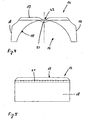
- the bearing insert 12 is shown in perspective. On the lower side of the bearing insert 12, the bearing receiving surface 15 can be seen. On the opposite side of the bearing receiving surface 15 sides a support surface 17, a front surface 18 and a rear surface 19 is formed.
- the support surface 17 on the top of the bearing insert 12 is in the assembled state on the underside of the receiving area 11 and here absorbs the forces acting in the direction perpendicular to the coupling plate 1.
- the front surface 18 and the rear surface 19 of the bearing insert 12 are arranged at a distance from each other substantially coincides with the distance between the side walls of the receiving area 12.
- a squish expansion joint 20 is formed between the receiving area and the bearing insert.
- the plastic material Under the occurring high surface pressures, the plastic material will deform and it is achieved a play-free seat on the one hand between bearing block 5 and bearing insert 12 and on the other hand between bearing insert 12 and coupling plate 1. It is advantageous that the inner surfaces of the receiving region 11 of the relatively large and heavy coupling plate 1 need not be specially processed.
- FIG. 4 the view is shown on the bearing insert 12 in the direction transverse to the direction of travel.
- a crush rib 21 On the bearing receiving surface 15 is a crush rib 21 and on the opposite side of the bearing insert 12 is a recess 22 is formed.
- the depression 22 and the crush rib 21 run parallel to one another and extend transversely to the direction of travel.
- a plurality of crush ribs 21 and on the opposite sides of the bearing insert 12 may also be formed a plurality of recesses 22.
- the front surface 18 and the rear surface 19 are deformed in the region of the Quetschdehnfuge 20. This ensures that the bearing insert 12 receives a play-free seat in the receiving area 12 on all sides and that the bearing block 5 is also received without play in the bearing cup 14.
- the high fifth wheel load of more than 30 tons which acts on the bearing assembly during operation, leads to that the osculation of the bearing block 5 on the bearing insert 12 becomes better as the service life progresses, that the bearing surfaces 13, 15 always interact better with one another and that the contact pattern of the bearing arrangement is always better.
Landscapes
- Engineering & Computer Science (AREA)
- Chemical & Material Sciences (AREA)
- Combustion & Propulsion (AREA)
- Transportation (AREA)
- Mechanical Engineering (AREA)
- Mechanical Operated Clutches (AREA)
- Rolling Contact Bearings (AREA)
- Handcart (AREA)
- Motorcycle And Bicycle Frame (AREA)
- Injection Moulding Of Plastics Or The Like (AREA)
- Mounting Of Bearings Or Others (AREA)
- Motor Power Transmission Devices (AREA)
- Turbine Rotor Nozzle Sealing (AREA)
- Support Of The Bearing (AREA)
Claims (7)
- Ensemble de palier pour attelages de semi-remorques comprenant une plaque d'attelage (1) pour l'accouplement d'un véhicule tracteur à une semi-remorque et pour atteler la semi-remorque sur le véhicule tracteur et un bloc palier (5) avec une surface de palier (13) essentiellement circulaire pour le support de la plaque d'attelage (1) par rapport au véhicule tracteur, une zone de réception (11) étant réalisée sur le côté inférieur de la plaque d'attelage (1) pour recevoir la surface de support (13) du bloc palier (5), un insert de palier (12) étant disposé dans la zone de réception (11) entre la surface de palier (13) et la plaque d'attelage (1), lequel présente une cavité de palier (14) avec une surface de réception de palier (15), qui est réalisée essentiellement en forme de cercle partiel et qui est disposée dans l'état monté de l'insert de palier (12) avec une correspondance de forme et sans jeu en coïncidence avec la surface de palier (13) du bloc palier (5), caractérisé en ce qu'au moins une nervure d'écrasement (21) s'étendant transversalement à la direction d'avance de la semi-remorque est réalisée sur la surface de réception de palier (15) dans l'état démonté et en ce que l'insert de palier (12) présente sur le côté opposé à la nervure d'écrasement (21) un renfoncement (22) s'étendant parallèlement à la nervure d'écrasement, une zone de paroi étant formée, laquelle est plus facilement élastique que les zones de paroi adjacentes lors d'une sollicitation perpendiculairement à la paroi.
- Ensemble de palier pour attelages de semi-remorques selon la revendication 1, caractérisé en ce que la surface de réception de palier (15) est disposée sous forme circulaire autour d'un axe s'étendant essentiellement transversalement à la direction d'avance de la semi-remorque.
- Ensemble de palier pour attelages de semi-remorques selon l'une quelconque des revendications 1 ou 2, caractérisé en ce que l'insert de palier (12) présente, sur les côtés opposés aux surfaces de réception de palier (15) une surface de support supérieure (17), une surface avant (18) s'étendant transversalement à la direction d'avance et une surface arrière (19) s'étendant transversalement à la direction d'avance, les pressions de surface entre l'insert de palier (12) et la zone de réception (11) de la plaque d'attelage (1) étant reçues dans l'état monté de manière répartie uniformément sur les surfaces coopérantes.
- Ensemble de palier pour attelages de semi-remorques selon l'une quelconque des revendications 1 à 3, caractérisé en ce que la surface avant (18) et la surface arrière (19) de l'insert de palier (12) sont espacées l'une de l'autre de telle sorte que dans l'état monté, un joint de dilatation et d'écrasement (20) soit formé entre l'insert de palier (12) et la zone de réception (11), et que le jeu entre les surfaces coopérantes soit compensé.
- Ensemble de palier pour attelages de semi-remorques selon l'une quelconque des revendications 1 à 4, caractérisé en ce que l'insert de palier (12) est réalisé en un matériau déformable plastiquement.
- Ensemble de palier pour attelages de semi-remorques selon l'une quelconque des revendications 1 à 5, caractérisé en ce que l'insert de palier (12) est réalisé en un matériau polymère.
- Ensemble de palier pour attelages de semi-remorques selon l'une quelconque des revendications 1 à 6, caractérisé en ce que l'insert de palier (12) peut être fabriqué d'une seule pièce par un procédé de moulage par injection de plastique.
Applications Claiming Priority (2)
| Application Number | Priority Date | Filing Date | Title |
|---|---|---|---|
| DE10040608 | 2000-08-16 | ||
| DE10040608A DE10040608A1 (de) | 2000-08-16 | 2000-08-16 | Lageranordnung für Sattelschlepperkupplungen |
Publications (3)
| Publication Number | Publication Date |
|---|---|
| EP1182120A2 EP1182120A2 (fr) | 2002-02-27 |
| EP1182120A3 EP1182120A3 (fr) | 2003-03-12 |
| EP1182120B1 true EP1182120B1 (fr) | 2006-10-04 |
Family
ID=7653007
Family Applications (1)
| Application Number | Title | Priority Date | Filing Date |
|---|---|---|---|
| EP01112239A Expired - Lifetime EP1182120B1 (fr) | 2000-08-16 | 2001-05-18 | Ensemble de palier pour attelage de semi-remorque |
Country Status (5)
| Country | Link |
|---|---|
| EP (1) | EP1182120B1 (fr) |
| AT (1) | ATE341477T1 (fr) |
| DE (2) | DE10040608A1 (fr) |
| DK (1) | DK1182120T3 (fr) |
| ES (1) | ES2269252T3 (fr) |
Family Cites Families (9)
| Publication number | Priority date | Publication date | Assignee | Title |
|---|---|---|---|---|
| US2784009A (en) * | 1954-08-02 | 1957-03-05 | Ray A Braunberger | Compression type shock absorbing bearings for fifth wheel tilting plates and the like |
| CH536731A (de) * | 1972-03-21 | 1973-05-15 | Fischer Ag Georg | Lagerung für Sattelkupplung |
| DE3040925C2 (de) * | 1980-10-30 | 1983-07-14 | Rockinger Spezialfabrik für Anhängerkupplungen GmbH & Co, 8000 München | Lagerung für eine Sattelkupplung |
| CH659802A5 (de) * | 1983-01-17 | 1987-02-27 | Fischer Ag Georg | Lagereinrichtung fuer eine sattelkupplung zum verbinden einer zugmaschine mit einem anhaengerwagen. |
| CH661481A5 (de) * | 1984-04-12 | 1987-07-31 | Fischer Ag Georg | Sattelkupplung. |
| DE3720698C2 (de) * | 1987-06-23 | 1998-07-02 | Hunger Walter Dr Ing E H | Sattelkupplung |
| US4892324A (en) * | 1988-08-22 | 1990-01-09 | Amsted Industries Incorporated | Fifth wheel mounting pad |
| DE4402526C2 (de) * | 1993-02-17 | 1998-12-10 | Fischer Georg Verkehrstechnik | Anordnung von Meßmitteln an einem eine Sattelzugmaschine und einen Sattelanhänger aufweisenden Sattelfahrzeug |
| DE19810502A1 (de) * | 1998-03-11 | 1999-09-16 | Fischer Georg Verkehrstechnik | Sattelkupplung zur Direktmontage auf einem Hilfsrahmen |
-
2000
- 2000-08-16 DE DE10040608A patent/DE10040608A1/de not_active Withdrawn
-
2001
- 2001-05-18 AT AT01112239T patent/ATE341477T1/de not_active IP Right Cessation
- 2001-05-18 ES ES01112239T patent/ES2269252T3/es not_active Expired - Lifetime
- 2001-05-18 EP EP01112239A patent/EP1182120B1/fr not_active Expired - Lifetime
- 2001-05-18 DE DE50111130T patent/DE50111130D1/de not_active Expired - Lifetime
- 2001-05-18 DK DK01112239T patent/DK1182120T3/da active
Also Published As
| Publication number | Publication date |
|---|---|
| DK1182120T3 (da) | 2007-02-05 |
| EP1182120A3 (fr) | 2003-03-12 |
| DE50111130D1 (de) | 2006-11-16 |
| EP1182120A2 (fr) | 2002-02-27 |
| DE10040608A1 (de) | 2002-02-28 |
| ES2269252T3 (es) | 2007-04-01 |
| ATE341477T1 (de) | 2006-10-15 |
Similar Documents
| Publication | Publication Date | Title |
|---|---|---|
| US4033601A (en) | Adjustable hitch ball mount for a trailer hitch | |
| EP1753652B2 (fr) | Fiches de raccordement | |
| EP0428890A2 (fr) | Dispositif d'attelage de remorque avec boîte dynamométrique | |
| CA1113523A (fr) | Attelage reglable | |
| DE69704742T2 (de) | Achsenkonstruktion für Fahrzeuge und Achseneingriffsplatte und Spannplatte dafür | |
| DE102018122577B4 (de) | Verbindungssystem, Kupplungssystem und Verfahren zur Verbindung eines Zugfahrzeugs mit einem Auflieger | |
| DE102017218796B4 (de) | Achsaufhängung | |
| US5947504A (en) | Trailer hitch safety apparatus | |
| EP1247715A1 (fr) | Dispositif de tamponnement et de traction pour véhicules ferroviaires | |
| EP1182120B1 (fr) | Ensemble de palier pour attelage de semi-remorque | |
| EP1173339A1 (fr) | Dispositif d'attelage entre un vehicule tracteur, en particulier un tracteur agricole, et une remorque | |
| DE3879404T2 (de) | Lagervorrichtung fuer kippbare fahrerkabinen von nutzfahrzeugen. | |
| EP0114046A2 (fr) | Paliers de sellette d'attelage de semi-remorque | |
| EP0921977A1 (fr) | Sellette de tracteur | |
| DE3031173A1 (de) | Hydraulische kolbengleisbremse zum abbremsen von eisenbahnwagen | |
| DE29521150U1 (de) | Wägevorrichtung für ein Fahrzeug | |
| EP1547900B1 (fr) | Agencement attachable pour roue | |
| DE102017215403B4 (de) | Federbaugruppe | |
| EP0191336A1 (fr) | Ensemble composé d'un outil de frappe et d'une unité de support | |
| EP4514676A1 (fr) | Système d'accouplement pour un véhicule tracteur | |
| DE10060781A1 (de) | Vorrichtung zum Befestigen von zwei Bauteilen | |
| DE3442518A1 (de) | Elastisch nachgiebiges lenkergelenk, insbesondere fuer achslenker von nutzfahrzeugen | |
| DE102006003772B4 (de) | Aufhängung mit einer an einer Befestigungskonsole schwenkbar gelagerten Lagerschlaufe | |
| DE9307886U1 (de) | Tragvorrichtung für einen heckseitigen Anbau an Kraftfahrzeugen | |
| DE102017222821A1 (de) | Lagervorrichtung, Aggregatträgersystem und Kraftfahrzeug |
Legal Events
| Date | Code | Title | Description |
|---|---|---|---|
| PUAI | Public reference made under article 153(3) epc to a published international application that has entered the european phase |
Free format text: ORIGINAL CODE: 0009012 |
|
| AK | Designated contracting states |
Kind code of ref document: A2 Designated state(s): AT BE CH CY DE DK ES FI FR GB GR IE IT LI LU MC NL PT SE TR |
|
| AX | Request for extension of the european patent |
Free format text: AL;LT;LV;MK;RO;SI |
|
| PUAL | Search report despatched |
Free format text: ORIGINAL CODE: 0009013 |
|
| AK | Designated contracting states |
Kind code of ref document: A3 Designated state(s): AT BE CH CY DE DK ES FI FR GB GR IE IT LI LU MC NL PT SE TR |
|
| AX | Request for extension of the european patent |
Extension state: AL LT LV MK RO SI |
|
| 17P | Request for examination filed |
Effective date: 20030703 |
|
| AKX | Designation fees paid |
Designated state(s): AT BE CH CY DE DK ES FI FR GB GR IE IT LI LU MC NL PT SE TR |
|
| 17Q | First examination report despatched |
Effective date: 20041208 |
|
| GRAP | Despatch of communication of intention to grant a patent |
Free format text: ORIGINAL CODE: EPIDOSNIGR1 |
|
| GRAS | Grant fee paid |
Free format text: ORIGINAL CODE: EPIDOSNIGR3 |
|
| GRAA | (expected) grant |
Free format text: ORIGINAL CODE: 0009210 |
|
| AK | Designated contracting states |
Kind code of ref document: B1 Designated state(s): AT BE CH CY DE DK ES FI FR GB GR IE IT LI LU MC NL PT SE TR |
|
| PG25 | Lapsed in a contracting state [announced via postgrant information from national office to epo] |
Ref country code: IT Free format text: LAPSE BECAUSE OF FAILURE TO SUBMIT A TRANSLATION OF THE DESCRIPTION OR TO PAY THE FEE WITHIN THE PRESCRIBED TIME-LIMIT;WARNING: LAPSES OF ITALIAN PATENTS WITH EFFECTIVE DATE BEFORE 2007 MAY HAVE OCCURRED AT ANY TIME BEFORE 2007. THE CORRECT EFFECTIVE DATE MAY BE DIFFERENT FROM THE ONE RECORDED. Effective date: 20061004 Ref country code: FI Free format text: LAPSE BECAUSE OF FAILURE TO SUBMIT A TRANSLATION OF THE DESCRIPTION OR TO PAY THE FEE WITHIN THE PRESCRIBED TIME-LIMIT Effective date: 20061004 Ref country code: IE Free format text: LAPSE BECAUSE OF FAILURE TO SUBMIT A TRANSLATION OF THE DESCRIPTION OR TO PAY THE FEE WITHIN THE PRESCRIBED TIME-LIMIT Effective date: 20061004 |
|
| REG | Reference to a national code |
Ref country code: GB Ref legal event code: FG4D Free format text: NOT ENGLISH |
|
| REG | Reference to a national code |
Ref country code: CH Ref legal event code: EP |
|
| GBT | Gb: translation of ep patent filed (gb section 77(6)(a)/1977) |
Effective date: 20061016 |
|
| REG | Reference to a national code |
Ref country code: IE Ref legal event code: FG4D Free format text: LANGUAGE OF EP DOCUMENT: GERMAN |
|
| REF | Corresponds to: |
Ref document number: 50111130 Country of ref document: DE Date of ref document: 20061116 Kind code of ref document: P |
|
| REG | Reference to a national code |
Ref country code: SE Ref legal event code: TRGR |
|
| REG | Reference to a national code |
Ref country code: DK Ref legal event code: T3 |
|
| ET | Fr: translation filed | ||
| PG25 | Lapsed in a contracting state [announced via postgrant information from national office to epo] |
Ref country code: PT Free format text: LAPSE BECAUSE OF FAILURE TO SUBMIT A TRANSLATION OF THE DESCRIPTION OR TO PAY THE FEE WITHIN THE PRESCRIBED TIME-LIMIT Effective date: 20070316 |
|
| REG | Reference to a national code |
Ref country code: ES Ref legal event code: FG2A Ref document number: 2269252 Country of ref document: ES Kind code of ref document: T3 |
|
| REG | Reference to a national code |
Ref country code: IE Ref legal event code: FD4D |
|
| PLBE | No opposition filed within time limit |
Free format text: ORIGINAL CODE: 0009261 |
|
| STAA | Information on the status of an ep patent application or granted ep patent |
Free format text: STATUS: NO OPPOSITION FILED WITHIN TIME LIMIT |
|
| 26N | No opposition filed |
Effective date: 20070705 |
|
| REG | Reference to a national code |
Ref country code: CH Ref legal event code: PL |
|
| PG25 | Lapsed in a contracting state [announced via postgrant information from national office to epo] |
Ref country code: MC Free format text: LAPSE BECAUSE OF NON-PAYMENT OF DUE FEES Effective date: 20070531 |
|
| PG25 | Lapsed in a contracting state [announced via postgrant information from national office to epo] |
Ref country code: CH Free format text: LAPSE BECAUSE OF NON-PAYMENT OF DUE FEES Effective date: 20070531 Ref country code: LI Free format text: LAPSE BECAUSE OF NON-PAYMENT OF DUE FEES Effective date: 20070531 |
|
| PG25 | Lapsed in a contracting state [announced via postgrant information from national office to epo] |
Ref country code: GR Free format text: LAPSE BECAUSE OF FAILURE TO SUBMIT A TRANSLATION OF THE DESCRIPTION OR TO PAY THE FEE WITHIN THE PRESCRIBED TIME-LIMIT Effective date: 20070105 |
|
| PGFP | Annual fee paid to national office [announced via postgrant information from national office to epo] |
Ref country code: DK Payment date: 20080509 Year of fee payment: 8 |
|
| PGFP | Annual fee paid to national office [announced via postgrant information from national office to epo] |
Ref country code: AT Payment date: 20080515 Year of fee payment: 8 |
|
| PGFP | Annual fee paid to national office [announced via postgrant information from national office to epo] |
Ref country code: BE Payment date: 20080620 Year of fee payment: 8 |
|
| PGFP | Annual fee paid to national office [announced via postgrant information from national office to epo] |
Ref country code: ES Payment date: 20090522 Year of fee payment: 9 Ref country code: NL Payment date: 20090520 Year of fee payment: 9 |
|
| PG25 | Lapsed in a contracting state [announced via postgrant information from national office to epo] |
Ref country code: CY Free format text: LAPSE BECAUSE OF FAILURE TO SUBMIT A TRANSLATION OF THE DESCRIPTION OR TO PAY THE FEE WITHIN THE PRESCRIBED TIME-LIMIT Effective date: 20061004 Ref country code: LU Free format text: LAPSE BECAUSE OF NON-PAYMENT OF DUE FEES Effective date: 20070518 |
|
| BERE | Be: lapsed |
Owner name: GEORG *FISCHER VERKEHRSTECHNIK G.M.B.H. Effective date: 20090531 |
|
| PGFP | Annual fee paid to national office [announced via postgrant information from national office to epo] |
Ref country code: GB Payment date: 20090528 Year of fee payment: 9 |
|
| REG | Reference to a national code |
Ref country code: DK Ref legal event code: EBP |
|
| PG25 | Lapsed in a contracting state [announced via postgrant information from national office to epo] |
Ref country code: AT Free format text: LAPSE BECAUSE OF NON-PAYMENT OF DUE FEES Effective date: 20090518 |
|
| PG25 | Lapsed in a contracting state [announced via postgrant information from national office to epo] |
Ref country code: DK Free format text: LAPSE BECAUSE OF NON-PAYMENT OF DUE FEES Effective date: 20090531 |
|
| PG25 | Lapsed in a contracting state [announced via postgrant information from national office to epo] |
Ref country code: BE Free format text: LAPSE BECAUSE OF NON-PAYMENT OF DUE FEES Effective date: 20090531 |
|
| REG | Reference to a national code |
Ref country code: NL Ref legal event code: V1 Effective date: 20101201 |
|
| GBPC | Gb: european patent ceased through non-payment of renewal fee |
Effective date: 20100518 |
|
| PG25 | Lapsed in a contracting state [announced via postgrant information from national office to epo] |
Ref country code: NL Free format text: LAPSE BECAUSE OF NON-PAYMENT OF DUE FEES Effective date: 20101201 |
|
| REG | Reference to a national code |
Ref country code: ES Ref legal event code: FD2A Effective date: 20110714 |
|
| PG25 | Lapsed in a contracting state [announced via postgrant information from national office to epo] |
Ref country code: GB Free format text: LAPSE BECAUSE OF NON-PAYMENT OF DUE FEES Effective date: 20100518 Ref country code: ES Free format text: LAPSE BECAUSE OF NON-PAYMENT OF DUE FEES Effective date: 20110704 |
|
| REG | Reference to a national code |
Ref country code: DE Ref legal event code: R081 Ref document number: 50111130 Country of ref document: DE Owner name: SAF-HOLLAND VERKEHRSTECHNIK GMBH, DE Free format text: FORMER OWNER: SAF-HOLLAND, INC., HOLLAND, US Effective date: 20110729 Ref country code: DE Ref legal event code: R081 Ref document number: 50111130 Country of ref document: DE Owner name: SAF-HOLLAND VERKEHRSTECHNIK GMBH, DE Free format text: FORMER OWNER: SAF-HOLLAND, INC., HOLLAND, MICH., US Effective date: 20110729 Ref country code: DE Ref legal event code: R081 Ref document number: 50111130 Country of ref document: DE Owner name: SAF-HOLLAND GMBH, DE Free format text: FORMER OWNER: SAF-HOLLAND, INC., HOLLAND, MICH., US Effective date: 20110729 |
|
| PG25 | Lapsed in a contracting state [announced via postgrant information from national office to epo] |
Ref country code: ES Free format text: LAPSE BECAUSE OF NON-PAYMENT OF DUE FEES Effective date: 20100519 |
|
| REG | Reference to a national code |
Ref country code: FR Ref legal event code: PLFP Year of fee payment: 16 |
|
| REG | Reference to a national code |
Ref country code: FR Ref legal event code: PLFP Year of fee payment: 17 |
|
| REG | Reference to a national code |
Ref country code: DE Ref legal event code: R082 Ref document number: 50111130 Country of ref document: DE Representative=s name: MUELLER SCHUPFNER & PARTNER PATENT- UND RECHTS, DE Ref country code: DE Ref legal event code: R081 Ref document number: 50111130 Country of ref document: DE Owner name: SAF-HOLLAND GMBH, DE Free format text: FORMER OWNER: SAF-HOLLAND VERKEHRSTECHNIK GMBH, 78224 SINGEN, DE |
|
| REG | Reference to a national code |
Ref country code: FR Ref legal event code: PLFP Year of fee payment: 18 |
|
| PGFP | Annual fee paid to national office [announced via postgrant information from national office to epo] |
Ref country code: IT Payment date: 20190521 Year of fee payment: 19 |
|
| REG | Reference to a national code |
Ref country code: DE Ref legal event code: R082 Ref document number: 50111130 Country of ref document: DE Representative=s name: MUELLER SCHUPFNER & PARTNER PATENT- UND RECHTS, DE |
|
| PGFP | Annual fee paid to national office [announced via postgrant information from national office to epo] |
Ref country code: TR Payment date: 20190508 Year of fee payment: 19 Ref country code: FR Payment date: 20190521 Year of fee payment: 19 |
|
| PGFP | Annual fee paid to national office [announced via postgrant information from national office to epo] |
Ref country code: DE Payment date: 20200319 Year of fee payment: 20 |
|
| PGFP | Annual fee paid to national office [announced via postgrant information from national office to epo] |
Ref country code: SE Payment date: 20200525 Year of fee payment: 20 |
|
| PG25 | Lapsed in a contracting state [announced via postgrant information from national office to epo] |
Ref country code: FR Free format text: LAPSE BECAUSE OF NON-PAYMENT OF DUE FEES Effective date: 20200531 |
|
| REG | Reference to a national code |
Ref country code: DE Ref legal event code: R071 Ref document number: 50111130 Country of ref document: DE |
|
| REG | Reference to a national code |
Ref country code: SE Ref legal event code: EUG |
|
| PG25 | Lapsed in a contracting state [announced via postgrant information from national office to epo] |
Ref country code: IT Free format text: LAPSE BECAUSE OF NON-PAYMENT OF DUE FEES Effective date: 20200518 |
|
| PG25 | Lapsed in a contracting state [announced via postgrant information from national office to epo] |
Ref country code: TR Free format text: LAPSE BECAUSE OF NON-PAYMENT OF DUE FEES Effective date: 20200518 |