EP1182125A2 - Unterbodenanordnung für ein Oberflächenpropeller-Vortriebssystem - Google Patents
Unterbodenanordnung für ein Oberflächenpropeller-Vortriebssystem Download PDFInfo
- Publication number
- EP1182125A2 EP1182125A2 EP01100029A EP01100029A EP1182125A2 EP 1182125 A2 EP1182125 A2 EP 1182125A2 EP 01100029 A EP01100029 A EP 01100029A EP 01100029 A EP01100029 A EP 01100029A EP 1182125 A2 EP1182125 A2 EP 1182125A2
- Authority
- EP
- European Patent Office
- Prior art keywords
- tunnel
- propeller
- bottom assembly
- closing member
- assembly according
- Prior art date
- Legal status (The legal status is an assumption and is not a legal conclusion. Google has not performed a legal analysis and makes no representation as to the accuracy of the status listed.)
- Granted
Links
- XLYOFNOQVPJJNP-UHFFFAOYSA-N water Substances O XLYOFNOQVPJJNP-UHFFFAOYSA-N 0.000 claims abstract description 17
- 230000005540 biological transmission Effects 0.000 description 5
- 238000000034 method Methods 0.000 description 5
- 238000001746 injection moulding Methods 0.000 description 3
- 230000033001 locomotion Effects 0.000 description 3
- 239000000243 solution Substances 0.000 description 3
- 238000010276 construction Methods 0.000 description 2
- 230000002706 hydrostatic effect Effects 0.000 description 2
- 239000002184 metal Substances 0.000 description 2
- 230000001788 irregular Effects 0.000 description 1
- 230000004048 modification Effects 0.000 description 1
- 238000012986 modification Methods 0.000 description 1
- 229920005989 resin Polymers 0.000 description 1
- 239000011347 resin Substances 0.000 description 1
- 238000007789 sealing Methods 0.000 description 1
Images



Classifications
-
- B—PERFORMING OPERATIONS; TRANSPORTING
- B63—SHIPS OR OTHER WATERBORNE VESSELS; RELATED EQUIPMENT
- B63H—MARINE PROPULSION OR STEERING
- B63H5/00—Arrangements on vessels of propulsion elements directly acting on water
- B63H5/07—Arrangements on vessels of propulsion elements directly acting on water of propellers
- B63H5/16—Arrangements on vessels of propulsion elements directly acting on water of propellers characterised by being mounted in recesses; with stationary water-guiding elements; Means to prevent fouling of the propeller, e.g. guards, cages or screens
-
- B—PERFORMING OPERATIONS; TRANSPORTING
- B63—SHIPS OR OTHER WATERBORNE VESSELS; RELATED EQUIPMENT
- B63B—SHIPS OR OTHER WATERBORNE VESSELS; EQUIPMENT FOR SHIPPING
- B63B1/00—Hydrodynamic or hydrostatic features of hulls or of hydrofoils
- B63B1/16—Hydrodynamic or hydrostatic features of hulls or of hydrofoils deriving additional lift from hydrodynamic forces
- B63B1/18—Hydrodynamic or hydrostatic features of hulls or of hydrofoils deriving additional lift from hydrodynamic forces of hydroplane type
-
- B—PERFORMING OPERATIONS; TRANSPORTING
- B63—SHIPS OR OTHER WATERBORNE VESSELS; RELATED EQUIPMENT
- B63B—SHIPS OR OTHER WATERBORNE VESSELS; EQUIPMENT FOR SHIPPING
- B63B1/00—Hydrodynamic or hydrostatic features of hulls or of hydrofoils
- B63B1/16—Hydrodynamic or hydrostatic features of hulls or of hydrofoils deriving additional lift from hydrodynamic forces
- B63B1/18—Hydrodynamic or hydrostatic features of hulls or of hydrofoils deriving additional lift from hydrodynamic forces of hydroplane type
- B63B2001/183—Hydrodynamic or hydrostatic features of hulls or of hydrofoils deriving additional lift from hydrodynamic forces of hydroplane type having non-floating planing surfaces, e.g. attached skis or plate-shaped bodies
-
- B—PERFORMING OPERATIONS; TRANSPORTING
- B63—SHIPS OR OTHER WATERBORNE VESSELS; RELATED EQUIPMENT
- B63H—MARINE PROPULSION OR STEERING
- B63H1/00—Propulsive elements directly acting on water
- B63H1/02—Propulsive elements directly acting on water of rotary type
- B63H1/12—Propulsive elements directly acting on water of rotary type with rotation axis substantially in propulsive direction
- B63H1/14—Propellers
- B63H1/18—Propellers with means for diminishing cavitation, e.g. supercavitation
- B63H2001/185—Surfacing propellers, i.e. propellers specially adapted for operation at the water surface, with blades incompletely submerged, or piercing the water surface from above in the course of each revolution
-
- B—PERFORMING OPERATIONS; TRANSPORTING
- B63—SHIPS OR OTHER WATERBORNE VESSELS; RELATED EQUIPMENT
- B63H—MARINE PROPULSION OR STEERING
- B63H5/00—Arrangements on vessels of propulsion elements directly acting on water
- B63H5/07—Arrangements on vessels of propulsion elements directly acting on water of propellers
- B63H5/08—Arrangements on vessels of propulsion elements directly acting on water of propellers of more than one propeller
Definitions
- the present invention concerns a bottom assembly suitable for producing a motor boat with a so-called "surface propeller” type of propulsion system.
- the surface propeller propulsion systems Compared to the immersed propeller propulsion systems, the surface propeller propulsion systems have a particularly reduced axis inclination. However if, on the one hand, it gives greater efficiency to the propulsion system, on the other hand it results in increased longitudinal hull dimensions.
- tunnels i.e. the recesses made at the base of the bottom which extend longitudinally in the stern portion of the hull.
- Each tunnel (one for each propeller shaft exiting from the bottom) consists of one or more walls that surround sideways and above the propeller shaft exiting from the bottom.
- tunnels have been adopted both with conventional transmission types, in which the kinematic chain is longitudinally aligned from the motor to the propeller, as well as with V-drive transmission types, in which the motor is situated at the stern, in a particularly set back position, above the propeller shaft.
- tunnel solution creates another problem.
- the presence of one or more tunnels alters the bottom by reducing its original hydrodynamic lift and giving rise to an increase in the hydrostatic pressure on the bottom itself. Consequently, under certain hull speed conditions, each tunnel tends to fill up with water during hull advancement and therefore the propeller is no longer able to work properly at the surface.
- each tunnel tends to fill up with water in a variable and often irregular way, thus compromising the efficiency of the surface propeller propulsion.
- the object of the present invention is to provide a bottom assembly equipped with one or more tunnels that allows the correct operation of the propulsion systems, particularly of the surface propeller types.
- Another object of the present invention is to provide a bottom assembly equipped with one or more tunnels that confers the maximum efficiency to the surface propeller propulsion system independently of the boat speed conditions and/or the rough conditions of the surrounding water.
- a bottom assembly for motor boats of the type comprising at least one longitudinal tunnel arranged at least at the stern portion of the bottom, the tunnel including one or more walls that surround, above and sideways, at least one propeller shaft exiting from the bottom to rotationally operate at least one propeller, characterised in that it includes at least one ground wall radiused to the surface of the bottom to close, at least partially, the cited at least one tunnel and limit the entry of water into the same.
- the ground wall is made of a closing member applied to the bottom.
- the tunnel is used during construction to help in the assembling phase of the various seal and/or support members for the propeller shaft, and thus is covered by the closing member.
- a bottom assembly made according to the present invention can include a hollow seat that surrounds each tunnel to allow the fixing of the closing member, hence maintaining the external surface continuity between the bottom and the closing member itself.
- the tunnel and the relative ground wall are integrally made in the bottom.
- This solution can be suitable, for instance, for hulls of metal construction, or anyway in the cases in which it would be possible to assemble the support and/or seal members for the propeller shaft also with the tunnel substantially closed on the bottom.
- the ground wall can include a suitably shaped end, or of reduced size, turned towards the propeller.
- the particular shape of the end portion e.g. obtained by making a cut, may prove necessary to obtain optimum performance depending on the cavitation characteristics of the propeller exiting from the tunnel.
- FIGS 1 to 3 illustrate some views of motor boats 1 equipped with surface propeller propulsion systems with bottoms made according to the known technique.
- the bottoms can be made with reinforced resins or similar by means of injection moulding procedures.
- the propulsion system of the motor boat 1 in general includes a motor unit 2, a reversing gearbox 3, a propeller shaft 4 and a propeller 5, near which is envisaged a support member 6 (fixed to the bottom 10) for the propeller shaft 4.
- the propeller shaft 4 exiting from bottom 10 is housed in a tunnel 20, the latter having one or more walls that surround, sideways and above, the propeller shaft 4.
- the support member 6 for the propeller shaft 4 can also be housed, if necessary, also just partially in tunnel 20.
- a tunnel 20 is envisaged substantially set in the stern portion of the same bottom.
- the bottom 10 shown as an example in Figure 2 is prepared with two tunnels 20, each to house a respective propeller shaft 4.
- Figure 3 represents the behaviour of the motor boat 1 of Figure 1 during its advancement in water.
- the modification of the bottom 10 set by the presence of a tunnel 20 involves a variation in the original lift of the same bottom. This results in an increase in the hydrostatic pressure on the bottom 10 that promotes the tunnel 20 to fill with water, with the result that the propeller 5 is no longer able to work properly at the surface.
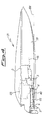
- the present invention proposes a motor boat 31 like that shown in Figure 4, which retains the same reference numbers that identify the substantially unchanged parts as regards those already identified in the previous Figures 1-3.
- a bottom assembly 30 is always equipped with a tunnel 20, but a ground wall 40 is envisaged, radiused to the bottom surface 30, allowing at least the partial closure of the tunnel 20 so as to restore, as much as possible, the original bottom lift and thus limit the entry of water into the same tunnel.
- the tunnel 20 by that time has already dynamically emptied itself of water and the ground wall 40 prevents the entry of water into the tunnel during the advancement of the same hull.
- This has the advantage of maintaining a constant performance of the boat, independently of its speed and rough conditions of the surrounding water.
- a bottom assembly made according to the present invention can be identically adopted in the boats with conventional propulsion systems, in which the kinematic chain is aligned in sequence from the motor unit 2 until the propeller 5, as in boats with "V-drive” type propulsion systems, in which the motor 22 (also here shown by a dotted line) occupies a more set back stern position.
- Figure 5 illustrates a possible embodiment of the invention, according to which the ground wall 40 of the bottom assembly 30 is realized by a closing member 41 that is applied to the bottom itself.
- a closing member 41 is outlined in the form of a substantially flat plate, but it should to understood that the closing member 41 can also take on a slightly bent or shaped form according the bottom shape to be restored at the tunnel 20.
- just one closing member 41 is shown for simplicity, it is also appropriate to point out that all the tunnels 20 in the bottom 30 (both tunnels 20 in the case shown) must be closed with a respective closing member 41.
- the closing member 41 is preferably fixed to the bottom 30 so as to maintain the external surface continuity between the bottom 30 and the closing member 41.
- a hollow seat 42 is envisaged that surrounds the tunnel 20 to receive the closing member 41.
- the seats 42 are easily obtained during injection moulding by suitable inserts set around the protruding templates designed to produce the tunnels 20.
- Each tunnel 20 can therefore be used to help with the assembly of the transmission parts that protrude from the bottom 30, i.e. the propeller shaft 4, the relative support 6 and a sealing element (not shown in Figure 5). After assembly, the tunnel 20 can be closed, also just partially, to restore as much as possible the original configuration of the bottom 30.
- the closing member can, for instance, have protruding portions or appendices that allow it to be fixed at the tunnel walls, or anyhow in any other suitable point which ensures particularly secure fixing.
- a closing member 44 can be suitably shaped, e.g. by cutting out part of it along a line 45, at its end portion turned towards the propeller (not shown in Figure 6).
- the shape or the reduction of the end portion is made depending on the cavitation characteristics of the propeller and can also therefore take on different forms to that shown as an example.
- Figure 7 shows an embodiment of a bottom assembly 50 in which the ground walls 40 of the tunnels 20 can be integrally made in the same bottom.
- This embodiment can be suitable, for instance, for metal hulls, or in any case, hulls for which it is possible to assemble, from the rear, the transmission members shown in Figure 7, especially at least the propeller shaft 4 and the seal and thrust bearing 8, in addition to the possible support member 6 in the case in which it is to be assembled (differently from that represented in Figure 8) also only partially inside the tunnel 20.
- ground wall 40 can be suitably shaped near the propeller, as already explained for the closing member 44 in the embodiment of Figure 6.
Landscapes
- Ocean & Marine Engineering (AREA)
- Fluid Mechanics (AREA)
- Chemical & Material Sciences (AREA)
- Engineering & Computer Science (AREA)
- Combustion & Propulsion (AREA)
- Mechanical Engineering (AREA)
- Physics & Mathematics (AREA)
- Lining And Supports For Tunnels (AREA)
- Compositions Of Oxide Ceramics (AREA)
- Excavating Of Shafts Or Tunnels (AREA)
- Structures Of Non-Positive Displacement Pumps (AREA)
- Motor Power Transmission Devices (AREA)
- Tunnel Furnaces (AREA)
Applications Claiming Priority (2)
| Application Number | Priority Date | Filing Date | Title |
|---|---|---|---|
| ITMI001898 | 2000-08-23 | ||
| IT2000MI001898A IT1318774B1 (it) | 2000-08-23 | 2000-08-23 | Complesso di carena per sistemi di propulsione ad elica di superficie. |
Publications (3)
| Publication Number | Publication Date |
|---|---|
| EP1182125A2 true EP1182125A2 (de) | 2002-02-27 |
| EP1182125A3 EP1182125A3 (de) | 2003-07-23 |
| EP1182125B1 EP1182125B1 (de) | 2011-05-25 |
Family
ID=11445725
Family Applications (1)
| Application Number | Title | Priority Date | Filing Date |
|---|---|---|---|
| EP01100029A Expired - Lifetime EP1182125B1 (de) | 2000-08-23 | 2001-01-05 | Unterbodenanordnung für ein Oberflächenpropeller-Vortriebssystem |
Country Status (5)
| Country | Link |
|---|---|
| US (1) | US6464549B2 (de) |
| EP (1) | EP1182125B1 (de) |
| AT (1) | ATE510760T1 (de) |
| ES (1) | ES2365596T3 (de) |
| IT (1) | IT1318774B1 (de) |
Cited By (2)
| Publication number | Priority date | Publication date | Assignee | Title |
|---|---|---|---|---|
| CN102556313A (zh) * | 2011-12-30 | 2012-07-11 | 深圳市海斯比船艇科技股份有限公司 | 可调式表面桨驱动系统及船艇 |
| EP2387636A4 (de) * | 2008-12-31 | 2014-04-09 | Lg Electronics Inc | Waschmaschine |
Families Citing this family (6)
| Publication number | Priority date | Publication date | Assignee | Title |
|---|---|---|---|---|
| US6823812B2 (en) * | 2001-05-25 | 2004-11-30 | Von Wolske James P. | Trim tabs and surface drive propeller bite control |
| US7143711B1 (en) | 2005-04-07 | 2006-12-05 | Wolske James P Von | Trim tab shape control system |
| US7631610B1 (en) | 2005-10-19 | 2009-12-15 | Wolske James P Von | Variable area trim tab and means to control water flow along a trim tab and added propeller guard including tunnel propellers |
| US7819711B1 (en) | 2006-02-15 | 2010-10-26 | James P. von Wolske | Retractable thrust reversing bucket for boat propeller |
| US8585450B2 (en) * | 2008-11-25 | 2013-11-19 | James P. von Wolske | Water flow limiting system for a boat including a water flow limiting plate positioned relative to propeller shaft and propeller of a boat for limiting water flow to the propeller |
| JP2025127575A (ja) * | 2024-02-21 | 2025-09-02 | ヤンマーホールディングス株式会社 | 船舶 |
Citations (1)
| Publication number | Priority date | Publication date | Assignee | Title |
|---|---|---|---|---|
| US4406635A (en) | 1981-04-22 | 1983-09-27 | Escher Wyss Gmbh | Marine vessel with at least one propeller |
Family Cites Families (8)
| Publication number | Priority date | Publication date | Assignee | Title |
|---|---|---|---|---|
| US3626894A (en) * | 1970-06-01 | 1971-12-14 | Penn Yan Boats Inc | Tunnel stern boat |
| US3793980A (en) * | 1971-12-30 | 1974-02-26 | Hydrodynamic Dev Corp | Marine propulsion system |
| US4231315A (en) * | 1977-05-12 | 1980-11-04 | Kawasaki Jukogyo Kabushiki Kaisha | Water-jet propulsion unit for vessels |
| US4941423A (en) * | 1986-06-16 | 1990-07-17 | Ocean Tech Marine, Inc. | Marine propulsion system |
| US4977845A (en) * | 1989-08-14 | 1990-12-18 | F. William Rundquist | Boat propulsion and handling system |
| US5405278A (en) * | 1993-09-22 | 1995-04-11 | S2 Yachts, Inc. | Recess flow plate for a boat hull |
| AU1576700A (en) * | 1998-12-04 | 2000-06-26 | E.P. Barrus Limited | A marine propulsion unit and a boat having a marine propulsion unit |
| US6863013B2 (en) * | 2000-10-12 | 2005-03-08 | Evan L. Noyes, Jr. | Boat propulsion system |
-
2000
- 2000-08-23 IT IT2000MI001898A patent/IT1318774B1/it active
-
2001
- 2001-01-05 ES ES01100029T patent/ES2365596T3/es not_active Expired - Lifetime
- 2001-01-05 AT AT01100029T patent/ATE510760T1/de not_active IP Right Cessation
- 2001-01-05 EP EP01100029A patent/EP1182125B1/de not_active Expired - Lifetime
- 2001-01-24 US US09/767,942 patent/US6464549B2/en not_active Expired - Lifetime
Patent Citations (1)
| Publication number | Priority date | Publication date | Assignee | Title |
|---|---|---|---|---|
| US4406635A (en) | 1981-04-22 | 1983-09-27 | Escher Wyss Gmbh | Marine vessel with at least one propeller |
Cited By (2)
| Publication number | Priority date | Publication date | Assignee | Title |
|---|---|---|---|---|
| EP2387636A4 (de) * | 2008-12-31 | 2014-04-09 | Lg Electronics Inc | Waschmaschine |
| CN102556313A (zh) * | 2011-12-30 | 2012-07-11 | 深圳市海斯比船艇科技股份有限公司 | 可调式表面桨驱动系统及船艇 |
Also Published As
| Publication number | Publication date |
|---|---|
| IT1318774B1 (it) | 2003-09-10 |
| EP1182125A3 (de) | 2003-07-23 |
| EP1182125B1 (de) | 2011-05-25 |
| ATE510760T1 (de) | 2011-06-15 |
| US6464549B2 (en) | 2002-10-15 |
| ES2365596T3 (es) | 2011-10-07 |
| US20020025736A1 (en) | 2002-02-28 |
| ITMI20001898A1 (it) | 2002-02-23 |
| ITMI20001898A0 (it) | 2000-08-23 |
Similar Documents
| Publication | Publication Date | Title |
|---|---|---|
| KR100657659B1 (ko) | 추진시스템 | |
| EP1182125B1 (de) | Unterbodenanordnung für ein Oberflächenpropeller-Vortriebssystem | |
| US3793980A (en) | Marine propulsion system | |
| WO1997046445A1 (en) | Marine propulsion and steering unit | |
| KR101608031B1 (ko) | 배에 대직경 스크류 프로펠러를 제공하는 방법 및 대직경 스크류 프로펠러를 포함하는 배 | |
| KR20160043926A (ko) | 선박용 추진 시스템 | |
| US5704306A (en) | Stern screw for a vessel as well as a vessel provided with such a stern screw | |
| KR101091759B1 (ko) | 직선 승강식 선미추진장치 | |
| US4667619A (en) | Bottom protector for a small boat | |
| EP1435325A1 (de) | Zurückziehbare Rumpfvorrichtungen für die Trimmsteuerung gleitenden Wasserfahrzeuge | |
| EP0872366A1 (de) | Zusatzauftrieb-, Antriebs- und Lenkungsvorrichtung für Mehrzweckfahrzeuge wie ein Amphibienfahrzeug | |
| US4810218A (en) | Marine propulsion device | |
| US8894453B2 (en) | Shallow-draft watercraft propulsion and steering apparatus | |
| US6116972A (en) | Auxiliary flotation, propulsion and steering gear for multipurpose vehicles with amphibian functions | |
| EP1182132B1 (de) | Vortriebssystem für Motorboote | |
| EP1970302A1 (de) | Antriebs- und Lenksystem mit schwingenden Tragflächen | |
| WO1985005339A1 (en) | Multi-hulled vessel | |
| KR20050083655A (ko) | 수중익을 장착한 선박 | |
| AU2941392A (en) | An elastomeric propeller having a flexible elastomeric covering | |
| US6957619B2 (en) | Hull having minimized wave-making characteristics | |
| WO2015179409A1 (en) | Hybrid vee-hull with sponsons | |
| EP2826703A1 (de) | Modulare Unterwasserfolie für ein Wasserfahrzeug | |
| US6305994B1 (en) | Hull for dual electric motor marine propulsion system | |
| US7927160B1 (en) | Variable pitch propeller | |
| KR102146797B1 (ko) | 활주부를 가지는 에어보트 |
Legal Events
| Date | Code | Title | Description |
|---|---|---|---|
| PUAI | Public reference made under article 153(3) epc to a published international application that has entered the european phase |
Free format text: ORIGINAL CODE: 0009012 |
|
| AK | Designated contracting states |
Kind code of ref document: A2 Designated state(s): AT BE CH CY DE DK ES FI FR GB GR IE IT LI LU MC NL PT SE TR |
|
| AX | Request for extension of the european patent |
Free format text: AL;LT;LV;MK;RO;SI |
|
| PUAL | Search report despatched |
Free format text: ORIGINAL CODE: 0009013 |
|
| AK | Designated contracting states |
Designated state(s): AT BE CH CY DE DK ES FI FR GB GR IE IT LI LU MC NL PT SE TR |
|
| AX | Request for extension of the european patent |
Extension state: AL LT LV MK RO SI |
|
| AKX | Designation fees paid | ||
| REG | Reference to a national code |
Ref country code: DE Ref legal event code: 8566 |
|
| RAP1 | Party data changed (applicant data changed or rights of an application transferred) |
Owner name: ZF MARINE ARCO SPA |
|
| 17P | Request for examination filed |
Effective date: 20040316 |
|
| RBV | Designated contracting states (corrected) |
Designated state(s): AT BE CH CY DE DK ES FI FR GB GR IE IT LI LU MC NL PT SE TR |
|
| 17Q | First examination report despatched |
Effective date: 20090508 |
|
| GRAP | Despatch of communication of intention to grant a patent |
Free format text: ORIGINAL CODE: EPIDOSNIGR1 |
|
| GRAS | Grant fee paid |
Free format text: ORIGINAL CODE: EPIDOSNIGR3 |
|
| GRAA | (expected) grant |
Free format text: ORIGINAL CODE: 0009210 |
|
| AK | Designated contracting states |
Kind code of ref document: B1 Designated state(s): AT BE CH CY DE DK ES FI FR GB GR IE IT LI LU MC NL PT SE TR |
|
| REG | Reference to a national code |
Ref country code: GB Ref legal event code: FG4D |
|
| REG | Reference to a national code |
Ref country code: CH Ref legal event code: EP |
|
| REG | Reference to a national code |
Ref country code: IE Ref legal event code: FG4D |
|
| REG | Reference to a national code |
Ref country code: DE Ref legal event code: R096 Ref document number: 60144684 Country of ref document: DE Effective date: 20110707 |
|
| REG | Reference to a national code |
Ref country code: NL Ref legal event code: VDEP Effective date: 20110525 |
|
| REG | Reference to a national code |
Ref country code: ES Ref legal event code: FG2A Ref document number: 2365596 Country of ref document: ES Kind code of ref document: T3 Effective date: 20111007 |
|
| REG | Reference to a national code |
Ref country code: GR Ref legal event code: EP Ref document number: 20110401908 Country of ref document: GR Effective date: 20110916 |
|
| PG25 | Lapsed in a contracting state [announced via postgrant information from national office to epo] |
Ref country code: PT Free format text: LAPSE BECAUSE OF FAILURE TO SUBMIT A TRANSLATION OF THE DESCRIPTION OR TO PAY THE FEE WITHIN THE PRESCRIBED TIME-LIMIT Effective date: 20110926 Ref country code: SE Free format text: LAPSE BECAUSE OF FAILURE TO SUBMIT A TRANSLATION OF THE DESCRIPTION OR TO PAY THE FEE WITHIN THE PRESCRIBED TIME-LIMIT Effective date: 20110525 |
|
| RAP2 | Party data changed (patent owner data changed or rights of a patent transferred) |
Owner name: ZF PADOVA S.R.L |
|
| PG25 | Lapsed in a contracting state [announced via postgrant information from national office to epo] |
Ref country code: AT Free format text: LAPSE BECAUSE OF FAILURE TO SUBMIT A TRANSLATION OF THE DESCRIPTION OR TO PAY THE FEE WITHIN THE PRESCRIBED TIME-LIMIT Effective date: 20110525 Ref country code: CY Free format text: LAPSE BECAUSE OF FAILURE TO SUBMIT A TRANSLATION OF THE DESCRIPTION OR TO PAY THE FEE WITHIN THE PRESCRIBED TIME-LIMIT Effective date: 20110525 Ref country code: FI Free format text: LAPSE BECAUSE OF FAILURE TO SUBMIT A TRANSLATION OF THE DESCRIPTION OR TO PAY THE FEE WITHIN THE PRESCRIBED TIME-LIMIT Effective date: 20110525 Ref country code: BE Free format text: LAPSE BECAUSE OF FAILURE TO SUBMIT A TRANSLATION OF THE DESCRIPTION OR TO PAY THE FEE WITHIN THE PRESCRIBED TIME-LIMIT Effective date: 20110525 |
|
| PG25 | Lapsed in a contracting state [announced via postgrant information from national office to epo] |
Ref country code: NL Free format text: LAPSE BECAUSE OF FAILURE TO SUBMIT A TRANSLATION OF THE DESCRIPTION OR TO PAY THE FEE WITHIN THE PRESCRIBED TIME-LIMIT Effective date: 20110525 |
|
| PG25 | Lapsed in a contracting state [announced via postgrant information from national office to epo] |
Ref country code: DK Free format text: LAPSE BECAUSE OF FAILURE TO SUBMIT A TRANSLATION OF THE DESCRIPTION OR TO PAY THE FEE WITHIN THE PRESCRIBED TIME-LIMIT Effective date: 20110525 |
|
| PLBE | No opposition filed within time limit |
Free format text: ORIGINAL CODE: 0009261 |
|
| STAA | Information on the status of an ep patent application or granted ep patent |
Free format text: STATUS: NO OPPOSITION FILED WITHIN TIME LIMIT |
|
| 26N | No opposition filed |
Effective date: 20120228 |
|
| REG | Reference to a national code |
Ref country code: DE Ref legal event code: R097 Ref document number: 60144684 Country of ref document: DE Effective date: 20120228 |
|
| PG25 | Lapsed in a contracting state [announced via postgrant information from national office to epo] |
Ref country code: MC Free format text: LAPSE BECAUSE OF NON-PAYMENT OF DUE FEES Effective date: 20120131 |
|
| REG | Reference to a national code |
Ref country code: CH Ref legal event code: PL |
|
| REG | Reference to a national code |
Ref country code: IE Ref legal event code: MM4A |
|
| PG25 | Lapsed in a contracting state [announced via postgrant information from national office to epo] |
Ref country code: CH Free format text: LAPSE BECAUSE OF NON-PAYMENT OF DUE FEES Effective date: 20120131 Ref country code: LI Free format text: LAPSE BECAUSE OF NON-PAYMENT OF DUE FEES Effective date: 20120131 |
|
| PG25 | Lapsed in a contracting state [announced via postgrant information from national office to epo] |
Ref country code: IE Free format text: LAPSE BECAUSE OF NON-PAYMENT OF DUE FEES Effective date: 20120105 |
|
| REG | Reference to a national code |
Ref country code: DE Ref legal event code: R082 Ref document number: 60144684 Country of ref document: DE Representative=s name: GODEMEYER BLUM LENZE PARTNERSCHAFT, PATENTANWA, DE Ref country code: DE Ref legal event code: R082 Ref document number: 60144684 Country of ref document: DE Representative=s name: GODEMEYER BLUM LENZE - WERKPATENT, DE Ref country code: DE Ref legal event code: R082 Ref document number: 60144684 Country of ref document: DE Representative=s name: GODEMEYER BLUM LENZE PATENTANWAELTE, PARTNERSC, DE |
|
| PG25 | Lapsed in a contracting state [announced via postgrant information from national office to epo] |
Ref country code: LU Free format text: LAPSE BECAUSE OF NON-PAYMENT OF DUE FEES Effective date: 20120105 |
|
| PGFP | Annual fee paid to national office [announced via postgrant information from national office to epo] |
Ref country code: TR Payment date: 20140103 Year of fee payment: 14 |
|
| PGFP | Annual fee paid to national office [announced via postgrant information from national office to epo] |
Ref country code: ES Payment date: 20141211 Year of fee payment: 15 Ref country code: GR Payment date: 20141211 Year of fee payment: 15 |
|
| REG | Reference to a national code |
Ref country code: FR Ref legal event code: PLFP Year of fee payment: 16 |
|
| REG | Reference to a national code |
Ref country code: GR Ref legal event code: ML Ref document number: 20110401908 Country of ref document: GR Effective date: 20160803 |
|
| PG25 | Lapsed in a contracting state [announced via postgrant information from national office to epo] |
Ref country code: GR Free format text: LAPSE BECAUSE OF NON-PAYMENT OF DUE FEES Effective date: 20160803 |
|
| REG | Reference to a national code |
Ref country code: FR Ref legal event code: PLFP Year of fee payment: 17 |
|
| REG | Reference to a national code |
Ref country code: ES Ref legal event code: FD2A Effective date: 20170224 |
|
| PG25 | Lapsed in a contracting state [announced via postgrant information from national office to epo] |
Ref country code: ES Free format text: LAPSE BECAUSE OF NON-PAYMENT OF DUE FEES Effective date: 20160106 |
|
| REG | Reference to a national code |
Ref country code: FR Ref legal event code: PLFP Year of fee payment: 18 |
|
| PGFP | Annual fee paid to national office [announced via postgrant information from national office to epo] |
Ref country code: FR Payment date: 20171211 Year of fee payment: 18 |
|
| PGFP | Annual fee paid to national office [announced via postgrant information from national office to epo] |
Ref country code: DE Payment date: 20171228 Year of fee payment: 18 Ref country code: GB Payment date: 20180103 Year of fee payment: 18 |
|
| REG | Reference to a national code |
Ref country code: DE Ref legal event code: R119 Ref document number: 60144684 Country of ref document: DE |
|
| GBPC | Gb: european patent ceased through non-payment of renewal fee |
Effective date: 20190105 |
|
| PG25 | Lapsed in a contracting state [announced via postgrant information from national office to epo] |
Ref country code: FR Free format text: LAPSE BECAUSE OF NON-PAYMENT OF DUE FEES Effective date: 20190131 Ref country code: DE Free format text: LAPSE BECAUSE OF NON-PAYMENT OF DUE FEES Effective date: 20190801 |
|
| PG25 | Lapsed in a contracting state [announced via postgrant information from national office to epo] |
Ref country code: GB Free format text: LAPSE BECAUSE OF NON-PAYMENT OF DUE FEES Effective date: 20190105 |
|
| PGFP | Annual fee paid to national office [announced via postgrant information from national office to epo] |
Ref country code: IT Payment date: 20200114 Year of fee payment: 20 |
|
| PG25 | Lapsed in a contracting state [announced via postgrant information from national office to epo] |
Ref country code: TR Free format text: LAPSE BECAUSE OF NON-PAYMENT OF DUE FEES Effective date: 20160105 |