EP1182129A1 - Kombination einer Schimmweste und einer Körperwärme rückhaltende Schutzumhüllung - Google Patents
Kombination einer Schimmweste und einer Körperwärme rückhaltende Schutzumhüllung Download PDFInfo
- Publication number
- EP1182129A1 EP1182129A1 EP00117397A EP00117397A EP1182129A1 EP 1182129 A1 EP1182129 A1 EP 1182129A1 EP 00117397 A EP00117397 A EP 00117397A EP 00117397 A EP00117397 A EP 00117397A EP 1182129 A1 EP1182129 A1 EP 1182129A1
- Authority
- EP
- European Patent Office
- Prior art keywords
- wearer
- pod
- lifejacket
- protective
- body portion
- Prior art date
- Legal status (The legal status is an assumption and is not a legal conclusion. Google has not performed a legal analysis and makes no representation as to the accuracy of the status listed.)
- Withdrawn
Links
- 230000001681 protective effect Effects 0.000 title claims description 93
- XLYOFNOQVPJJNP-UHFFFAOYSA-N water Substances O XLYOFNOQVPJJNP-UHFFFAOYSA-N 0.000 claims description 69
- 239000000463 material Substances 0.000 claims description 38
- 210000000707 wrist Anatomy 0.000 claims description 20
- 230000000295 complement effect Effects 0.000 claims description 12
- KAATUXNTWXVJKI-UHFFFAOYSA-N cypermethrin Chemical compound CC1(C)C(C=C(Cl)Cl)C1C(=O)OC(C#N)C1=CC=CC(OC=2C=CC=CC=2)=C1 KAATUXNTWXVJKI-UHFFFAOYSA-N 0.000 claims description 9
- 230000001605 fetal effect Effects 0.000 claims description 8
- 210000004247 hand Anatomy 0.000 claims description 5
- 230000036760 body temperature Effects 0.000 claims description 4
- 102100033121 Transcription factor 21 Human genes 0.000 description 56
- 101710119687 Transcription factor 21 Proteins 0.000 description 56
- 210000002105 tongue Anatomy 0.000 description 7
- 230000013011 mating Effects 0.000 description 6
- 230000004083 survival effect Effects 0.000 description 6
- 230000002631 hypothermal effect Effects 0.000 description 5
- 238000007654 immersion Methods 0.000 description 4
- 230000008901 benefit Effects 0.000 description 3
- 239000013535 sea water Substances 0.000 description 3
- JOYRKODLDBILNP-UHFFFAOYSA-N Ethyl urethane Chemical compound CCOC(N)=O JOYRKODLDBILNP-UHFFFAOYSA-N 0.000 description 2
- 239000004677 Nylon Substances 0.000 description 2
- 230000000694 effects Effects 0.000 description 2
- 238000000034 method Methods 0.000 description 2
- 229920001778 nylon Polymers 0.000 description 2
- 239000004033 plastic Substances 0.000 description 2
- 229920003023 plastic Polymers 0.000 description 2
- 229920001084 poly(chloroprene) Polymers 0.000 description 2
- 230000000135 prohibitive effect Effects 0.000 description 2
- 230000000717 retained effect Effects 0.000 description 2
- 238000010792 warming Methods 0.000 description 2
- 230000033228 biological regulation Effects 0.000 description 1
- 230000003111 delayed effect Effects 0.000 description 1
- 230000000994 depressogenic effect Effects 0.000 description 1
- 238000005188 flotation Methods 0.000 description 1
- 239000006260 foam Substances 0.000 description 1
- 239000003562 lightweight material Substances 0.000 description 1
- 230000002035 prolonged effect Effects 0.000 description 1
- 239000012858 resilient material Substances 0.000 description 1
- 230000000979 retarding effect Effects 0.000 description 1
- 238000006467 substitution reaction Methods 0.000 description 1
- 239000002982 water resistant material Substances 0.000 description 1
Images






Classifications
-
- B—PERFORMING OPERATIONS; TRANSPORTING
- B63—SHIPS OR OTHER WATERBORNE VESSELS; RELATED EQUIPMENT
- B63C—LAUNCHING, HAULING-OUT, OR DRY-DOCKING OF VESSELS; LIFE-SAVING IN WATER; EQUIPMENT FOR DWELLING OR WORKING UNDER WATER; MEANS FOR SALVAGING OR SEARCHING FOR UNDERWATER OBJECTS
- B63C9/00—Life-saving in water
- B63C9/06—Floatable closed containers with accommodation for one or more persons inside
- B63C9/065—Floatable closed containers with accommodation for one or more persons inside for one person
-
- B—PERFORMING OPERATIONS; TRANSPORTING
- B63—SHIPS OR OTHER WATERBORNE VESSELS; RELATED EQUIPMENT
- B63C—LAUNCHING, HAULING-OUT, OR DRY-DOCKING OF VESSELS; LIFE-SAVING IN WATER; EQUIPMENT FOR DWELLING OR WORKING UNDER WATER; MEANS FOR SALVAGING OR SEARCHING FOR UNDERWATER OBJECTS
- B63C9/00—Life-saving in water
- B63C9/08—Life-buoys, e.g. rings; Life-belts, jackets, suits, or the like
Definitions
- This invention relates to a protective pod that is carried in a folded condition within a pod containment envelope at the rear of a personal flotation device (i.e. lifejacket) so as to be accessible to and worn by a civilian and military airman or a seaman who finds himself in or about to enter a cold water environment while awaiting rescue from an emergency situation.
- the protective pod creates a sealed chamber within which a small volume of water is trapped and heated by the wearer's body heat to slow a drop in the wearer's body temperature to better enable him to survive his environment.
- a civilian e.g. a boater, a cruise ship passenger, a pilot, etc.
- a member of the military may find it necessary to abandon his boat or plane.
- the individual may have to enter the water while awaiting rescue.
- his body temperature will quickly drop to a level where survival becomes impossible if his rescue is delayed for any prolonged period of time.
- Waterproof garments are known that offer some protection to a wearer against hypothermia and the effects of low temperature, such as that which would be encountered by civilians or military personnel who face an emergency situation while at sea.
- these garments are typically worn in lieu of a lifejacket or other conventional personal floatation device. Accordingly, the wearer will quickly tire and/or have trouble staying afloat while awaiting his rescue.
- the ability of many garments to insulate the wearer's body against a significant drop in temperature may be negligible. That is, garments such as clothing do not fully surround and protect the wearer's body and/or function as a warming device, such that the wearer may find himself facing hypothermia after a relatively short time in the cold water environment. Consequently, the wearer's chances of survival will be relatively minimal, especially where the water temperature is low and the time to await rescue is more than a few minutes.
- immersion or survival suits are typically expensive, high-end emergency garments that are used by commercial fishermen and oil rig workers, where the chances of unexpected immersion in a cold water environment are high and the high per person cost of the immersion suit is not deemed cost prohibitive.
- the immersion or survival suits would not usually be considered appropriate nor cost effective for most private non-commercial, recreational boaters, commercial cruise ship passengers and even highly mobile military personnel where the bulk and weight of hypothermia protective devices would be a serious consideration.
- a protective pod which is capable of significantly retarding the loss of a wearer's body heat.
- the pod can be worn by a civilian or military seaman or airman who must enter a cold water environment while awaiting rescue from an emergency situation.
- the protective pod is preferably manufactured from a readily foldable, highly water resistant ripstop nylon material with urethane backing.
- the protective pod is carried in a folded or rolled up condition within a pod containment envelope at the back of a personal floatation device (commonly known as a lifejacket).
- the protective pod is always and only worn in combination with the lifejacket, but not in substitution thereof.
- the personal floatation device would be a Type I, II or III personal floatation device (as defined by 46 Code of Federal Regulations Section 160 et. Seq.).
- the pod containment envelope of the lifejacket is formed by a series of flaps that are folded over one another to enclose the protective pod.
- a rip cord that is attached to the flaps inside the containment envelope is manually accessible so as to be grasped and pulled by the wearer to cause the containment envelope to open and the protective pod in its collapsed condition to fall out to permit deployment whether the wearer has already entered or is about to enter the water.
- the protective pod is connected to the lifejacket by means of a detachable tether so as to prevent the pod from sinking or otherwise drifting out of reach from the user.
- a hood to be worn over the head of the wearer is stored in a rolled up condition within a foldover collar that runs around the top of the lifejacket. The wearer simply lifts up on the collar to grab and remove the hood therefrom. After it is unrolled, the hood is pulled over the wearer's head and held snugly thereagainst by pulling a drawstring and closing a chin flap.
- the wearer dons the protective pod by inserting his legs and torso into a body portion thereof. Thereafter, the user inserts his arms and hands through watertight sleeves. The user pulls the protective pod up around the lifejacket and then zips up a heavy grade zipper extending vertically along the front of the protective pod. There is a cinching cord running through a channel around the top of the protective pod which the user pulls to close the pod snugly around the foldover collar of the lifejacket.
- a Type I, II or III personal floatation device is designed to be buoyant so that the water line is below the lifejacket collar.
- Pulling upwardly on the cinching cords causes the protective pod to be effectively shortened so as to also minimize the volume of water that will be trapped inside the protective pod. Minimizing the volume of water inside the protective pod directly enhances the warming of that water by the body heat of the wearer and thereby inhibits and slows the loss of the wearer's body heat, thus prolonging his survivability while immersed in the cold water environment awaiting rescue.
- the wearer uses a hook and loop fastener closure to secure a wrap around collar located at the top of the protective pod in a snug position outside the hood and around the collar of the lifejacket so as to be crossed over and attached to the pod in front of his neck to minimize the opportunity for outside water to enter the interior of the pod.
- FIGs. 1-11 of the drawings where details of a unique personal floatation device (i.e. commonly known as a lifejacket 100) are disclosed.
- a lifejacket 100 both the lifejacket 100 and the soon to be described protective pod (designated 1 in FIGs. 12-16) are worn, one over the other, by civilian or military personnel who find themselves in a cold water environment while awaiting rescue from an emergency situation.
- the lifejacket 100 illustrated at FIGs. 1-11 is a Type I, II or III personal floatation device pursuant to 46 C.F.R. 160 et seq.
- lifejacket 100 is manufactured so as to be buoyant to maintain the water line below the lifejacket collar 130 which surrounds the neck of the wearer.
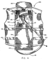
- the protective pod 1 is efficiently folded into a compact package and carried within a pod containment envelope (designated 132 in FIGs. 2-4) at the rear of the lifejacket 100.
- the protective pod 1 is stored within the pod containment envelope 132 so as to be readily available to the wearer and easily deployed in an emergency situation in order to provide the wearer with the ability to prolong his survival while awaiting rescue in a cold water environment.
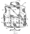
- the lifejacket 100 shown in FIGs. 1-3 is manufactured from a lightweight, water resistant material. As is best shown in FIGs. 1 and 2, a plurality of floatation foam pads 102 are carried within interior compartments at the front and rear of lifejacket 100 to provide the wearer with the buoyancy necessary to remain afloat while drifting in the water. A suitable number of pockets 104 are sewn to the front of the lifejacket 100. The pockets 104 are closed by means of opposing strips 106 of complementary and well known hook and loop fastener material that are located under the flaps 108 and over the top of the pockets 104. A number of ports 110 are formed through each of the pocket 104 to enable sea water to escape therefrom.
- the lifejacket 100 is closed around the body of the wearer by a vertically extending, heavy grade zipper 112.
- a tab 114 at the top of lifejacket 100 is detachably retained across the top of the zipper by means of opposing strips 116 of complementary hook and loop fastener material.
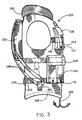
- upper, intermediate and lower tightening straps 118, 119 and 120 extend horizontally around the lifejacket. As is best shown in FIGs. 2 and 3, the tightening straps 118-120 are tunneled under the aforementioned pockets 104 at the front of lifejacket 100 and supported by loops 105 at the rear of the lifejacket.
- Opposing ends of the tightening straps 118-120 at the front of the lifejacket 100 have conventional, push-button actuated, snap and catch fastener members 122 and 124 that are detachably connected to one another to hold the straps together.
- a drawstring 126 is located within a hollow channel (designated 128 in FIG. 2) that runs circumferentially around the bottom of the lifejacket 100. By pulling on opposite free ends of the drawstring 126, the lifejacket 100 will be tightened around the waist of the wearer. It may be appreciated that the vertically extending zipper 112 as well as the horizontally extending tightening straps 118-120 and drawstring 126 cooperate to hold the life vest 100 close to the wearer's body so as to reduce the loss of the wearer's body heat and keep the wearer's body positioned high in relation to the waterline.
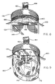
- An important detail of the lifejacket 100 of this invention is a foldover collar 130 that surrounds the top of the lifejacket to fit around the wearer's neck. As will be described when referring to FIGs. 6-11, the collar 130 is unfolded to permit the wearer to gain access to a hood (designated 160 in FIGs. 8-11) that is stored in a rolled up condition within the collar 130.
- a hood designated 160 in FIGs. 8-11
- Another important detail of the lifejacket 100 is the previously mentioned pod containment envelope 130 which is located at the rear of lifejacket 100 to enclose the protective body heat retaining pod 1 that is stored in a folded condition within envelope 132 prior to deployment.
- the pod containment envelope 132 includes a top flap 133, a bottom flap 134, a rear flap 135, and a pair of opposite side flaps 136 and 137 which, in the packaged position of FIGs. 2 and 3, are folded over one another to enclose the protective pod 1 and thereby facilitate the storage and transport thereof at a non-obtrusive location at the rear of lifejacket 100.
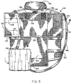
- the rear flap 135 is affixed to the back of the lifejacket 100, and the top flap 133, the bottom flap 134 and the side flaps 136 and 137 are all pivotally attached (e.g. sewn) to respective ends of the rear flap 135 so that in the unpackaged position of FIG. 5, the containment envelope 132 will be opened to cause the protective pod 1 to fall outwardly therefrom so as to become accessible to the wearer.
- strips 138 of hook fastener material are affixed to the outside of the top flat 133
- an opposing strip 140 of complementary hook fastener material is affixed to the inside of the bottom flap 134
- strips 142 of loop fastener material are affixed to the outside of one side flap 136
- a strip 144 of complementary hook fastener material is affixed to the inside of the opposite side flap 137.
- the side flap 136 is then folded over the protective pod 1 to expose the strips 142 of loop fastener material.
- the opposite side flap 137 is folded over side flap 136, such that the strips 142 and 144 of complementary hook and loop fastener material are moved into mating engagement.
- the top flap 136 is folded downwardly over the side flap 137, and the bottom flap 134 is folded upwardly over the top flap 133, such that the strips 138 and 140 of complementary hook and loop fastener material are moved into mating engagement.
- a manually accessible rip cord 148 is provided to enable the wearer to gain access to the protective pod 1 that is folded and stored within the containment envelope 132 at the rear of the lifejacket 100.
- the rip cord 148 extends from a corner of the side flap 137 of containment envelope 132, through a guide loop 150 that is affixed to a side of the lifejacket 100, and to a corner of the bottom flap 134.
- the application of a pulling force against the ripcord 148 causes the bottom and the side flaps 134 and 137 to unfold and the containment envelope 132 to correspondingly open, whereby the protective pod 1 will drop out in the manner illustrated at FIG. 5.
- the guide loop 150 holds the rip cord 144 close to the side of lifejacket 100 so that the rip cord can be easily located, grasped and pulled by the wearer.
- a detachable tether 152 extends from the front of pod 1 (best shown in FIG. 12), over the wearer's shoulder, to a plastic D-ring 154 that depends from the upper tightening strap 118 at the front of lifejacket 100.
- Simple spring action clips 156 can be used to couple opposite ends of the tether 152 to the protective pod 1 and to the D-ring 154 of the lifejacket 100.
- the wearer can quickly disconnect the tether 152 once he has hold of the protective pod 1 and is ready to begin the deployment thereof while in the cold water environment.
- the deployment of the hood 160 is now described after the wearer dons the lifejacket 100 of FIGs. 1-3.
- the hood 160 is carried in a rolled up condition within the foldover collar 130 at the top of lifejacket 100. A portion of the hood 160 is affixed to the lifejacket 100 below the collar 130.
- the collar 130 is initially folded over itself and closed against the lifejacket 100 by means of the mating engagement of a strip 162 of loop fastener material along a tab 164 at the rear of collar 130 and an opposing strip 166 of hook fastener material at the rear of the lifejacket 100 above the pod containment envelope 132.
- the wearer To remove the hood 160, the wearer first lifts up on the tab 164 to break the engagement between the opposing strips 162 and 166 of complementary hook and loop fastener material (best shown in FIG. 7).
- the wearer grasps the foldover collar 130 at the rear of the lifejacket 100 and pulls upwardly thereon. The wearer can now grab and pull the rolled up hood 160 out from the collar 130.
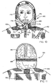
- the hood 160 is shown removed and unrolled from the collar 130 and hanging down the back of the lifejacket 100 so as to be ready to be pushed towards the front of the wearer and pulled over the wearer's head, as shown in FIG. 10 and 11.
- a horizontally extending strip 168 of hook material (best shown in FIGs. 8 and 11) runs around the back of the hood 160 for a purpose that will soon be described.
- an open window 170 is located in the front of the hood 160 to surround the face of the wearer in the manner shown by FIG. 10.
- a channel 172 extends around the periphery of the window 170, and a draw string 174 runs through the channel.
- the wearer can tighten the window 170 around his face to prevent water from readily splashing to the inside of the hood 160.
- Each end of the drawstring 174 is associated with a conventional push button actuated cord stopper 176 (best shown in FIGs. 9 and 10) which is a tightening device that prevents the drawstring from sliding back into the channel 172 so as to avoid a loosening of the window 170 after the window has been tightened around the wearer's face.
- a chin flap 178 is closed against the hood 160 by means of the mating engagement of opposing strips (only one of which 180 being shown) of complementary hook and loop fastener material.
- the hood fits snugly over the wearer's head and around the wearer's face to further prevent the escape of the wearer's body heat.
- strips of light reflecting tape 182 are affixed over the top of the hood 160 (best shown in FIG. 11).
- a suitable reflecting tape 182 that is adapted to reflect both sunlight and moonlight and is suitable to be affixed to the hood 160 is that manufactured by the 3M Company under the commercial name SOLAS.
- the protective body heat retaining pod 1 of the present invention is described in the unfolded condition following its removal from the pod containment envelope 132 at the rear of the lifejacket 100 in FIG. 5.
- the protective pod 1 is manufactured from a durable, lightweight material that is capable of being folded to enable a civilian or military seaman or airman who wears the pod 1 and finds himself in a cold water environment to survive the conditions of his environment while awaiting rescue.
- the protective pod 1 is constructed from a water resistant ripstop nylon with a urethane backing. Some or all of the pod 1 may be brightly colored to help locate a wearer who is awaiting rescue in the water following his evacuation from a boat or a plane.
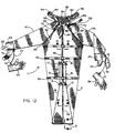
- the protective pod 1 is an enclosure having a body portion 2 that is adjustably sized to surround the torso and legs of a wearer (e.g. either an adult or a child). As described above, the protective pod 1 is used in combination with and not in lieu of the lifejacket 100 shown in FIGs. 1-3. Thus, after the wearer dons the protective pod 1, the lifejacket 100 will perform its usual function of keeping the wearer afloat. A closure 3 runs along the bottom of the body portion 2 to seal the pod 1 from its water filled environment. Therefore, and as an important feature of the protective body heat retaining pod 1, when the pod is worn in a water filled environment (as shown in FIG.
- the body portion 2 of protective pod 1 will be too long to comfortably surround and enclose the legs of the wearer.
- a relatively large volume of water could be undesirably trapped within the chamber 40 of the body portion 2 that lies below the water line.
- This large volume of water would be less efficiently heated by the wearer, resulting in a rate of body heat loss which would increase in relation to the increase in water volume. It is well known that a person immersed in cold water may reduce body heat loss, in part, by assuming an upright fetal position to further conserve body heat.
- a pair of vertical cinching cords 9 and 10 extend from eyelets in the closure 3 along the bottom of the body portion 2 and through respective openings in lower and upper guide tabs 12 and 14 that are stitched to and depend from the front of the body portion 2 at the base of a soon to be described zipper 36.
- the guide tabs 12 and 14 are arranged in spaced vertical alignment one above the other with the upper guide tab 14 disposed at about the midpoint of the body portion 2.
- Each of the free ends of the cinching cords 9 and 10 which project from the upper guide tab 14 is fed through a push bottom actuated cord stopper 17 and 18 (similar to the cord stopper 176 that were described when referring to FIGs. 9 and 10).
- the cord stoppers 17 and 18 are tightening devices that have holes through which the vertical cinching cords 9 and 10 are adapted to slide.
- Each stopper 17 and 18 also has a pair of push button actuated jaws (not shown) that are normally clamped around a cinching cord 9 or 10 to prevent the cinching cord from sliding through the holes in the first and second guide tabs 12 and 14. When the push button of a cord stopper is depressed, the jaws thereof are temporarily opened to enable the cinching cord 9 and 10 to slide relative to the upper and lower guide tabs 12 and 14.
- the pulling force applied to the cinching cords 9 and 10 is transferred to the closure 3 to cause the bottom of the body portion 2 of pod 1 to be correspondingly pulled upwardly, whereby the wearer's legs are drawn into the fetal position at which to advantageously reduce the empty space within chamber 40 so as to inhibit the loss of the wearer's body heat.
- the push button of the cord stopper 17 or 18 is then released so that the jaws thereof resume their original clamping force against the cinching cord 9 or 10 to prevent the cinching cord from sliding downwardly through the guide tabs 12 and 14 to extend the protective pod 1 to the elongated configuration shown in FIGs. 12 and 13.
- An additional benefit of holding the protective pod 1 in the shortened configuration of FIG. 14 is to enable the wearer to maintain the fetal position without having to unnecessarily exert energy and thereby speed up the loss of his body heat.
- each sleeve 22 and 23 is affixed (e.g. stitched) to the body portion 2 along a diagonal seam.
- a cylindrical cuff 24 that is manufactured from a resilient (e.g. neoprene) material is affixed (e.g. stitched) to the end of each sleeve 22 and 23.
- the cuffs 24 are covered with loop fastener material.
- a tongue 25 projects axially outward, and a wrist wrap 74 projects radially outward from each cylindrical cuff 24.
- a pad 75 covered with hook fastener material is affixed to the end of each wrist wrap 74.
- the aforementioned cuff 24 is initially cut from a flat piece of resilient material covered with loop fastener material and having the tongue 25 and wrist wrap 74 extending coextensively from one another and forming an approximate right angle (FIG. 19A).
- the pad 75 of hook fastener material is located on one side and at the tip of wrist wrap 74.
- the wrist wrap 74 is rolled over the tongue 25 to establish a generally cylindrical cuff configuration through which to receive the hand and surround the wrist of the wearer.
- the wrist wrap 74 is retained in the cylindrical configuration over top of the tongue 25 by means of a single box stitch 77 (FIG. 19B).
- the cylindrical portion of the cuff 24 is stitched to the open end of one of the sleeves (e.g. 22) which extend from the protective pod 1.
- a cuff which is a mirror image of the cuff 24 shown in FIG. 19 is then stitched to the other sleeve 23.
- FIGs. 19-21 The use of the resilient cuffs 24 to prevent sea water from entering the body portion 2 of protective pod 1 via sleeves 22 and 23 is now described while referring concurrently to FIGs. 19-21.
- the wearer When the wearer don's the pod 1, his arms are received through the sleeves 22 and 23 so that his wrists are surrounded by the cylindrical cuffs 24 and his hands lie flush against the axially projecting tongues 25 of cuffs 24 (best shown in FIG. 19).
- the wearer grasps the radially projecting wrist flap 74 with his other hand (best shown in FIG. 20). While continuing to hold the tongue 25 (to prevent the cuff from rotating around his wrist), the wearer pulls the wrist wrap 74 and winds it snugly around the cuff 24.
- the wrist wrap 74 is wound up around itself and over the cuff 24 until the pad 75 that is covered with the hook fastener material is moved into mating engagement with the loop fastener material with which the cuff 24 is covered (best shown in FIG. 21). Accordingly, with the wrist wrap 74 wound securely around itself and tightened against the wearer's wrist, a reliable closure is established by which to prevent water from the wearer's environment from entering the sleeves 22 and 23. In this regard, the same method as just described is repeated for the other one of the cylindrical cuffs 24 to maintain the substantially watertight characteristic of the protective body heat retaining pod 1 surrounding the wearer.
- a pair of conventional diver's wet suit gloves 26, or the like, are connected to the cuffs 24 by means of tethers 27. After the wrist wraps 74 are securely wrapped around the cuffs 24, the gloves 26 are donned while still attached to their tethers 27. The wearer fits his hands into the gloves 26, whereby the gloves extend over the cuffs 24 to warm the wearer's hands (best shown in FIG. 14).
- the body portion 2 of protective pod 1 includes upper, lower and intermediate cinching straps 28, 30 and 32 which extend horizontally therearound. As is best shown in FIGs. 13 and 16, the horizontally extending cinching straps 28, 30 and 32 are held in uniform spaced alignment with one another by means of belt loops 33 sewn to the back of the body portion 2 of the protective pod 1. As is best shown in FIG. 12, the area of the body portion 2 of protective pod 1 lying below the lower cinching strap 30 is permanently sealed by means of a stitched seam 34 that runs vertically along the front of the body portion 2 to form the watertight chamber 40 (of FIG.
- the area of the body portion 2 of protective pod 1 lying above the lower cinching strap 30 can be either closed or opened by means of a vertically extending, commercially available water tight zipper 36.
- the zipper 36 is opened, the wearer will be able to climb into (or out of) the protective pod 1 whether the wearer is located on dry land or in a cold water environment.
- the zipper 36 is then closed to preserve the water tight chamber 40 within the body portion 2.
- a pull string (designated 20 in FIG. 12) is attached to the zipper to facilitate its being lowered or raised by the wearer.
- Each of the upper, lower and intermediate cinching straps 28, 30 and 32 is provided with an identical closure means by which to hold the body portion 2 of protective pod 1 in snug engagement with the wearer's waist and chest to further reduce the size of the chamber 40 within which water is trapped.
- FIG. 16 details of the closure means for the upper, lower and intermediate cinching straps 28, 30 and 32 are now described.
- a pair of conventional plastic D-rings 42 and 44 are attached to the front of the body portion 2 by means of respective flexible loops 50 and 52 so that the D-rings are spaced across from one another at opposite sides of the vertically extending zipper 36.
- One end (designated 28a in FIG. 16) of each cinching strap (e.g. 28) is fixedly attached to the body portion 2 at loop 52.
- the opposite free end (designated 28b in FIG. 16) of the cinching strap 28 is covered with adjacent regions 46 and 48 of complementary hook and loop fastener material extending along one side thereof.
- the zipper 36 is closed and the opposing fixed and free ends 28a and 28b of cinching strap 28 are joined together. More particularly, the free end 28b of the cinching strap 28 is pulled through the side-by-side pair of D-rings 42 and 44 so as to extend across the zipper 36. The free end 28b of the cinching strap 28 along which the adjacent regions 46 and 48 of hook and loop fastener material are located is then turned back upon itself and folded over the top of each of the D-rings 44 and 42.
- the free end 28b of the cinching strap 28 is then pulled in a direction away from the fixed end 28a at loop 52 so as to eliminate slack and ensure a tight fit across the zipper 36 and around the body portion 2.
- the folded over free end 28b of the cinching strap is laid over itself at which time the adjacent regions 46 and 48 of hook and loop fastener materials are detachably mated together to hold the fixed and free ends 28a and 28b.
- the protective pod 1 in order to assure that sea water from the wearer's environment outside of the protective pod 1 does not undesirably enter the body portion 2 and at the same time increase the volume of water trapped within the sealed chamber 40, the protective pod 1 is provided with an elongated wrap around collar that is manufactured from a resilient (e.g. neoprene) material that is adapted to be stretched when pulled.
- the collar has first and second flap members 54 and 56 that project outwardly and in opposite directions from a neck support member 58.
- the wrap around pod collar is manufactured so that each of the first and second flap members 54 and 56 and the neck support member 58 thereof includes an integral component of loop fastener material 60.
- Opposite free ends 62 and 64 of a drawstring are available at the front of the body portion 2 of protective pod 1 below the wrap around pod collar.
- the drawstring runs through a channel 65 that extends around the neck of the body portion 2.
- the channel 65 of the body portion 2 will be tightened around the collar 130 of the lifejacket 100 that is worn below the pod.
- Each free end 62 and 64 of the drawstring is associated with a cord stopper 66 and 68 to prevent the free ends 62 and 64 from sliding inwardly of the channel 65 once the free ends 62 and 64 are pulled to tighten the channel 65 of body portion 2 around the collar 130 of lifejacket 100.
- each of the free ends 62 and 64 of the drawstring are received through an elongated loop or tunnel 70 and 72 that is covered with hook fastener material.
- the wearer Once the wearer has pulled the hood (designated 160 in FIGs. 10 and 11) from the lifejacket 100 over his head, donned the protective body heat retaining pod 1, moved the watertight zipper 36 vertically upward to the closed position, secured the watertight wrist wraps 74 around cuffs 24, adjusted the length of cinching cords 9 and 10, fastened the cinching straps 28, 30 and 32, and pulled the free ends 62 and 64 of the drawstring to tighten the channel 65 around the collar 130 of lifejacket 100, he is ready to wrap the pod collar around his neck in the manner shown in FIG. 14.
- the wearer grasps one of the first or second resilient collar flap members 54 and 56 that is manufactured with loop fastener material 60 and stretches it diagonally across his body to be detachably connected to one of the loops 70 and 72 that is covered with hook fastener material.
- the wearer grasps the other one of the first or second collar flap members 54 and 56 and stretches it diagonally across his body to be detachably connected to the other loop 70 and 72. Accordingly, as is best shown in FIG. 14, the first and second collar flap members 54 and 56 of the pod collar cross over one another above the wearer's chest and in front of the wearer's neck to complete the water tight closure of the pod 1 around the neck of the wearer.
- the back of the hood 160 that is pulled from the foldover collar 130 of lifejacket 100 is provided with a strip 168 of hook fastener material extending therearound.
- the layer 60 of loop fastener material which covers the neck support member 58 of the pod collar is moved into mating engagement with the strip 168 of complementary hook fastener material of the hood 160, whereby the wrap around pod collar is securely attached to the back of the hood 160.
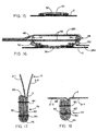
- FIGs. 17 and 18 of the drawings illustrate the manner in which the protective body heat retaining pod 1 is manufactured so as to create a substantially watertight enclosure to surround the wearer who awaits his rescue in a cold water environment.
- FIG. 17 refers to a horizontal seam 76 that seals the closure 3 running along the bottom of body portion 2.
- FIG. 18 refers to the vertical seam 34 running along the front of body portion 2. Although only two seams 34 and 76 are shown and described, it is to be understood that all of the seams of the protective pod 1 are created in the manner illustrated by either one of FIGs. 17 and 18 and are therefore provided with the same advantages.
- the front and back sides (designated 2-1 and 2-2) of the bottom of the body portion 2 of pod 1 are brought together in face-to-face alignment with one another.
- the face-to-face alignment of the front and back sides 2-1 and 2-2 is turned a first time to establish a first fold 78 and then a second time in the same direction so as to lie under the first fold 78 and establish a second fold 80.
- a commercially available thermal bonding material 82 such as that manufactured by 3M Company under the trademark THERMO-BOND FILM, is applied between the opposite facing front and back sides 2-1 and 2-2 of body portion 2 that undergo the first and second folds 78 and 80.
- the folds 78 and 80 of the front and back sides 2-1 and 2-2 of body portion 2 are sewn together by means of parallel lock stitches 84 whereupon the seam 76 will be held closed.
- the thermal bonding material 82 covers the holes created by the stitches 84 and helps to preserve the watertight seal along the closure 3.
- opposing vertical edges designated 2-3 and 2-4 at the front of body portion 2 of protective pod 1 are brought together in face-to-face alignment.
- the face-to-face alignment of opposing edges 2-3 and 2-4 is turned a first time to establish a first fold 86 and then a second time under the first fold 86 to establish a second fold 88.
- a thermal bonding material 82 is applied between the opposite facing edges 2-3 and 2-4 of body portion 2 that undergo the first and second folds 86 and 88.
- the folds 86 and 88 of the opposite vertical edges 2-3 and 2-4 of body portion 2 are sewn together by means of parallel lock stitches 90 whereupon the seam 34 will also be held closed.
- the seams 34 and 76 of FIGs. 17 and 18 are twice folded so as to lie outside (i.e. above) the body portion 2 of protective pod 1. Accordingly, the seams 34 and 76 are sized and located to create external attachment points for the guide tabs 12 and 14, and the like, whereby to advantageously avoid leakage in order to maintain the water resistant nature of the seams 34 and 76 and preserve the substantially watertight quality of pod 1.
- the wearer is now fully enclosed by a virtually watertight protective body heat retaining pod 1 which is used in combination with the lifejacket 100 to keep him afloat in a cold water environment while reducing the loss of life sustaining body heat and prolonging the time to avoid hypothermia, whereby to increase the wearer's chances for surviving and being rescued from an otherwise life threatening emergency situation.
- the combination life jacket 100 and protective body heat retaining pod 1 have been described above for use by a wearer who finds himself within a cold water environment, this combination may also be used by those outside of water who seek protection from the elements while awaiting their rescue from an emergency and possibly life threatening situation (e.g. including those in a boat floating at sea or lost in the wilderness).
Landscapes
- Engineering & Computer Science (AREA)
- Mechanical Engineering (AREA)
- Ocean & Marine Engineering (AREA)
- Professional, Industrial, Or Sporting Protective Garments (AREA)
Priority Applications (1)
| Application Number | Priority Date | Filing Date | Title |
|---|---|---|---|
| EP00117397A EP1182129A1 (de) | 2000-08-24 | 2000-08-24 | Kombination einer Schimmweste und einer Körperwärme rückhaltende Schutzumhüllung |
Applications Claiming Priority (1)
| Application Number | Priority Date | Filing Date | Title |
|---|---|---|---|
| EP00117397A EP1182129A1 (de) | 2000-08-24 | 2000-08-24 | Kombination einer Schimmweste und einer Körperwärme rückhaltende Schutzumhüllung |
Publications (1)
| Publication Number | Publication Date |
|---|---|
| EP1182129A1 true EP1182129A1 (de) | 2002-02-27 |
Family
ID=8169508
Family Applications (1)
| Application Number | Title | Priority Date | Filing Date |
|---|---|---|---|
| EP00117397A Withdrawn EP1182129A1 (de) | 2000-08-24 | 2000-08-24 | Kombination einer Schimmweste und einer Körperwärme rückhaltende Schutzumhüllung |
Country Status (1)
| Country | Link |
|---|---|
| EP (1) | EP1182129A1 (de) |
Cited By (2)
| Publication number | Priority date | Publication date | Assignee | Title |
|---|---|---|---|---|
| CN102602515A (zh) * | 2011-01-18 | 2012-07-25 | 朱明龙 | 远洋海难救生仓 |
| CN111994227A (zh) * | 2020-09-02 | 2020-11-27 | 东台市海鸥航海设备有限公司 | 一种具有后置式折叠机构的安全救生衣 |
Citations (9)
| Publication number | Priority date | Publication date | Assignee | Title |
|---|---|---|---|---|
| US3155992A (en) * | 1962-09-05 | 1964-11-10 | Glenn A Shewmake | Life raft |
| US3744053A (en) | 1970-02-11 | 1973-07-10 | Sanders Nuclear Corp | Liquid loop garments |
| US3768761A (en) * | 1971-07-26 | 1973-10-30 | Bendix Corp | Inflatable life raft |
| US4533335A (en) | 1983-03-04 | 1985-08-06 | Toyo Bussan Kabushiki Kaisha | Cold-proof water-proof garment |
| US4533333A (en) | 1980-08-08 | 1985-08-06 | The United States Of America As Represented By The Secretary Of The Navy | Helicopter extractable cold weather/water liferaft |
| US4739522A (en) | 1987-02-18 | 1988-04-26 | Burlington Industries, Inc. | Cold weather garment with improved buoyancy |
| CA1245914A (en) * | 1987-09-11 | 1988-12-06 | Alan T. Wilby | Ocean survival suit |
| DE19601068A1 (de) * | 1996-01-13 | 1997-07-17 | Rohnstock Hans Juergen | Rettungskugel für Flugzeuge, Drachenflieger, Schiffe und Hochhausbrände |
| WO1997032776A1 (en) * | 1994-10-18 | 1997-09-12 | Morten Heldahl | Method and equipment for securing a person, for marine use |
-
2000
- 2000-08-24 EP EP00117397A patent/EP1182129A1/de not_active Withdrawn
Patent Citations (9)
| Publication number | Priority date | Publication date | Assignee | Title |
|---|---|---|---|---|
| US3155992A (en) * | 1962-09-05 | 1964-11-10 | Glenn A Shewmake | Life raft |
| US3744053A (en) | 1970-02-11 | 1973-07-10 | Sanders Nuclear Corp | Liquid loop garments |
| US3768761A (en) * | 1971-07-26 | 1973-10-30 | Bendix Corp | Inflatable life raft |
| US4533333A (en) | 1980-08-08 | 1985-08-06 | The United States Of America As Represented By The Secretary Of The Navy | Helicopter extractable cold weather/water liferaft |
| US4533335A (en) | 1983-03-04 | 1985-08-06 | Toyo Bussan Kabushiki Kaisha | Cold-proof water-proof garment |
| US4739522A (en) | 1987-02-18 | 1988-04-26 | Burlington Industries, Inc. | Cold weather garment with improved buoyancy |
| CA1245914A (en) * | 1987-09-11 | 1988-12-06 | Alan T. Wilby | Ocean survival suit |
| WO1997032776A1 (en) * | 1994-10-18 | 1997-09-12 | Morten Heldahl | Method and equipment for securing a person, for marine use |
| DE19601068A1 (de) * | 1996-01-13 | 1997-07-17 | Rohnstock Hans Juergen | Rettungskugel für Flugzeuge, Drachenflieger, Schiffe und Hochhausbrände |
Cited By (2)
| Publication number | Priority date | Publication date | Assignee | Title |
|---|---|---|---|---|
| CN102602515A (zh) * | 2011-01-18 | 2012-07-25 | 朱明龙 | 远洋海难救生仓 |
| CN111994227A (zh) * | 2020-09-02 | 2020-11-27 | 东台市海鸥航海设备有限公司 | 一种具有后置式折叠机构的安全救生衣 |
Similar Documents
| Publication | Publication Date | Title |
|---|---|---|
| US6328618B1 (en) | Combination lifejacket and protective body heat retaining pod | |
| CA2376834C (en) | Combination backpack and protective body heat retaining pod | |
| US4416641A (en) | Anti-exposure jacket | |
| US5702279A (en) | Inflatable swimmer's safety belt, life preserver/life vest | |
| US4752263A (en) | Custom underwater diving system | |
| US4187570A (en) | Ship escape and survival system | |
| US4943252A (en) | Avalanche flotation ball | |
| US6066016A (en) | Inflatable transportable water craft for survival or recreational applications | |
| US6036562A (en) | 2-step swimmer's safety belt inflatable into a life preserver and a life vest | |
| US4673366A (en) | Exposure suit with an attached lifejacket | |
| US20040157514A1 (en) | Variably configured inflatable personal flotation device also serving as an emergency distress marker | |
| US20110177732A1 (en) | Cold water survival apparatus | |
| US20060270290A1 (en) | Lightweight personal rescue tube flotation device | |
| US9205900B2 (en) | Harness assembly having a deployable inflatable life raft attached thereto | |
| WO2010045536A1 (en) | Child carriers and methods for protecting a young child | |
| US4137586A (en) | Survival suit | |
| US2782430A (en) | Flotation and thermal protecting apparel | |
| RU2609182C1 (ru) | Спасательное надувное индивидуальное средство | |
| US20130203310A1 (en) | Convertible emergency device | |
| US20040078876A1 (en) | Immersion suit | |
| US6860775B2 (en) | Anti-exposure flotation suit | |
| US4017926A (en) | Life-saving garment | |
| GB2330517A (en) | Submarine Escape Suit incorporating a Life Raft | |
| EP1182129A1 (de) | Kombination einer Schimmweste und einer Körperwärme rückhaltende Schutzumhüllung | |
| GB2082979A (en) | Survival Vest With Attached Hypothermia-resisting Hood |
Legal Events
| Date | Code | Title | Description |
|---|---|---|---|
| PUAI | Public reference made under article 153(3) epc to a published international application that has entered the european phase |
Free format text: ORIGINAL CODE: 0009012 |
|
| 17P | Request for examination filed |
Effective date: 20000928 |
|
| AK | Designated contracting states |
Kind code of ref document: A1 Designated state(s): AT BE CH CY DE DK ES FI FR GB GR IE IT LI LU MC NL PT SE |
|
| AX | Request for extension of the european patent |
Free format text: AL;LT;LV;MK;RO;SI |
|
| AKX | Designation fees paid |
Free format text: AT BE CH CY DE DK ES FI FR GB GR IE IT LI LU MC NL PT SE |
|
| 17Q | First examination report despatched |
Effective date: 20030224 |
|
| RAP1 | Party data changed (applicant data changed or rights of an application transferred) |
Owner name: FLEISCHLI, JACK A. |
|
| RIN1 | Information on inventor provided before grant (corrected) |
Inventor name: FLEISCHLI, JACK A. |
|
| STAA | Information on the status of an ep patent application or granted ep patent |
Free format text: STATUS: THE APPLICATION IS DEEMED TO BE WITHDRAWN |
|
| 18D | Application deemed to be withdrawn |
Effective date: 20030909 |