EP1182673A2 - Schalter - Google Patents
Schalter Download PDFInfo
- Publication number
- EP1182673A2 EP1182673A2 EP01119340A EP01119340A EP1182673A2 EP 1182673 A2 EP1182673 A2 EP 1182673A2 EP 01119340 A EP01119340 A EP 01119340A EP 01119340 A EP01119340 A EP 01119340A EP 1182673 A2 EP1182673 A2 EP 1182673A2
- Authority
- EP
- European Patent Office
- Prior art keywords
- conductor plate
- contact
- center terminal
- support arm
- switch device
- Prior art date
- Legal status (The legal status is an assumption and is not a legal conclusion. Google has not performed a legal analysis and makes no representation as to the accuracy of the status listed.)
- Granted
Links
Images



Classifications
-
- H—ELECTRICITY
- H01—ELECTRIC ELEMENTS
- H01H—ELECTRIC SWITCHES; RELAYS; SELECTORS; EMERGENCY PROTECTIVE DEVICES
- H01H13/00—Switches having rectilinearly-movable operating part or parts adapted for pushing or pulling in one direction only, e.g. push-button switch
- H01H13/02—Details
- H01H13/26—Snap-action arrangements depending upon deformation of elastic members
- H01H13/28—Snap-action arrangements depending upon deformation of elastic members using compression or extension of coil springs
-
- H—ELECTRICITY
- H01—ELECTRIC ELEMENTS
- H01H—ELECTRIC SWITCHES; RELAYS; SELECTORS; EMERGENCY PROTECTIVE DEVICES
- H01H5/00—Snap-action arrangements, i.e. in which during a single opening operation or a single closing operation energy is first stored and then released to produce or assist the contact movement
- H01H5/04—Energy stored by deformation of elastic members
- H01H5/14—Energy stored by deformation of elastic members by twisting of torsion members
Definitions
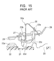
- FIGS. 13 to 15 The structure of a conventional quick-acting switch device is shown in FIGS. 13 to 15.
- FIG. 13 is a longitudinal sectional view showing an OFF state of the switch device
- FIG. 14 is a longitudinal sectional view showing an ON state of the switch device
- FIG. 15 is a partial explanatory view of a contact mechanism section.
- the center terminal 23 is made of a conductive metal plate or the like, and includes a support plate retaining projection 23a for retaining the support plate 27 and a leaf spring retaining projection 23b for retaining the leaf spring 31.
- the support plate retaining projection 23a and the leaf spring retaining projection 23b have, respectively, retaining V-grooves 23c and 23d formed nearly opposed to each other.
- the support plate 27 and the leaf spring 30 are retained at one end by the retaining groves 23c and 23d.
- the conductor plate 28 is similarly made of a conductive metal plate, and has at its center an opening where the support plate retaining projection 23a and the leaf spring retaining projection 23b can be loosely fitted, and the movable contact 29 at one end.
- the conductor plate 28 is movably mounted on the center terminal 23 while one end of the support plate 27 is retained at one inner end of the opening, and the other end of the opening is retained by the leaf spring 30.
- the leaf spring 30 is made of an elastic thin metal plate, and is substantially V-shaped. One end of the leaf spring 30 is retained by the retaining V-groove 23d of the leaf spring retaining projection 23b of the center terminal 23, and the other end thereof is retained on the inner side of the opening of the conductor plate 28 opposite from the side where the support plate 27 is retained.
- the leaf spring 30 is placed in a bent form between the center terminal 23 and the conductor plate 28. Adjacent to the top of the nearly V-shaped leaf spring 30, an operating projection 30a is formed so as to drive the conductor plate 28 when the slide member 31 slides.
- the support plate 27 and the leaf spring 30 are made of a platelike material, the shape is complicated, and the material yield is low. Since the support plate 27 and the leaf spring 30 contact with the center terminal 23 at cut edge portions, they are prone to be worn, and the reliability of the contact portion is decreased.
- the shape is simplified, the material yield is improved, and machinablility and dimensional accuracy can be maintained easily. Moreover, since the support arm and the spring member are retained by the conductor plate and the center terminal on the arc-shaped surfaces, they are inhibited from being worn, and the reliability of the contact portion is improved.
- the spring member is formed of a helical torsion spring.
- the shape is simplified, machinablility and dimensional accuracy can be easily maintained, and the cost can be reduced, compared with a case in which a leaf spring or the like is formed by press-molding a metal plate.
- the spring member is made of a round wire of circular cross section, it is engaged with the center terminal and the conductor plate on the arc-shaped surfaces. Therefore, a smooth sliding is possible, scraping or the like are avoided, and the reliability of the contact is improved.
- the slide member has an operating face portion formed of an inclined surface
- the conductor plate has a contact portion to be contacted with the operating face portion
- the operating face portion slides in contact with the contact portion with the sliding of the slide member so as to shift the conductor plate in the direction nearly perpendicular to the sliding direction.
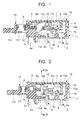
- FIGS. 1 to 12 show a switch device according to an embodiment of the present invention.
- FIG. 1 is a longitudinal sectional view showing an OFF state of the switch device
- FIG. 2 is a longitudinal sectional view showing an ON state of the switch device
- FIG. 3 is a plan view of the switch device in which a cover and a slide member are partly cut away
- FIG. 4 is a sectional view of the switch device, taken along line IV-IV in FIG. 2
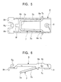
- FIG. 5 is a plan view showing the engaging state of a conductor plate and a support arm
- FIG. 6 is a front view showing the engaging state
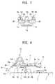
- FIG. 7 is a side view showing the engaging state.
- FIGS. 8 to 12 show are explanatory view showing the operating states of a contact mechanism section of the switch device.
- FIG. 1 is a longitudinal sectional view showing an OFF state of the switch device
- FIG. 2 is a longitudinal sectional view showing an ON state of the switch device
- FIG. 3 is a plan view of the switch device in
- FIG. 8 is an explanatory view showing an initial (OFF) state of the contact mechanism section
- FIG. 9 is an explanatory view showing a state immediately before the conductor plate moves
- FIG. 10 is an explanatory view showing a state in which the conductor plate moves and contacts are closed
- FIG. 11 is an explanatory view showing a state in which the slide member is pressed to its full-stroke position after being locked
- FIG. 12 is an explanatory view showing a state immediately before the slide member is unlocked and the conductor plate moves to open the contacts.
- a casing 1 is made of an insulating material, such as a synthetic resin, and is shaped like a box which has an opening at the top.
- a pair of holding portions 1a are formed inside the opening of the casing 1.
- a fixed terminal 2 made of a conductive metal plate and having a fixed contact 2a on its upper surface is placed on the inner bottom surface of each of the holding portions 1a, and a center terminal 3 similarly made of a conductive metal plate is placed adjacent thereto.
- the support arm retaining projection 3a and the spring retaining projection 3b respectively have retaining grooves 3c and 3d nearly opposed to each other.
- the support arm 7 and the helical torsion spring 10 are retained, at one end, by the retaining grooves 3c and 3d.
- the retaining grooves 3c and 3d are shaped like an arc in accordance with the wire diameters of the support arm 7 and the helical torsion spring 10.
- the support arm 7 is made of a conductive, elastic, round wire and is substantially U-shaped.
- the support arm 7 has a retaining shaft 7a to be retained by the retaining groove 3c of the support arm retaining projection 3a, and a pair of opposing flexible arm pieces 7b extending from the retaining shaft 7a.
- Each of the arm pieces 7b has, at its leading end, a bent portion 7c to be rotatably engaged with a retaining hole 8c formed in a side wall 8a of a conductor plate 8, which will be described later.
- the support arm 7 is combined with the conductor plate 8 by engaging the bent portions 7c with the retaining holes 8c, and the arm pieces 7b are elastically urged toward the side walls 8a of the conductor plate 8 by their own elasticity.
- the conductor plate 8 is similarly made of a conductive metal plate.
- the conductor plate 8 has opposing side walls 8a on both sides, and a window portion 8b at the center.
- a pair of retaining holes 8c are respectively formed in the side walls 8a, and the bent portions 7c of the support arm 7 are rotatably engaged therewith.
- Adjacent to the retaining holes 8c, regulating projections 8e each having an inclined face 8d are formed so as to contact the arm pieces 7b of the support arm 7.
- the inclined faces 8d of the regulating projections 8e project toward the upper surfaces of the side walls 8a.
- the regulating projections 8e By forming the regulating projections 8e on the side walls 8a, when the conductor plate 8 is shifted in a direction nearly perpendicular to the sliding direction and the movable contact 9 moves into contact with the fixed contact 2a, the arm pieces 7b move upward along the inclined faces 8d with the movement of the conductor plate 8. Therefore, the arm pieces 7b are compressed inward by the regulating projections 8e, and the elastic contact pressure with the inclined faces 8d are increased.
- the support arm 7 is loosely fitted in the window portion 8b, and the support arm retaining projection 3a and the helical torsion spring 10 are also loosely fitted therein.
- a guide groove 8f is formed to be fitted on and guided by the support arm retaining projection 3a when the conductor plate 8 is mounted on the center terminal 3. By forming the guide groove 8f, the conductor plate 8 is movably positioned and mounted on the center terminal 3.
- the movable contact 9 is fixed.
- the retaining holes 8c are formed, and the bent portions 7c of the support arm 7 are engaged therewith.
- a hook portion 8g is formed so as to retain one end of the helical torsion spring 10, and is movably mounted on the center terminal 3.
- arc-shaped contact portions 8h are formed so as to contact an operating face portion 11d of the slide member 11, which will be described later, in order to shift the conductor plate 8 in the direction nearly perpendicular to the sliding direction.
- the helical torsion spring 10 serving as the spring member is formed by coiling a conductive, elastic, round wire, and has a pair of spring pieces 10a and 10b.
- One of the spring pieces 10a is retained by the retaining groove 3d of the spring retaining projection 3b of the center terminal 3, and the other spring piece 10b is retained by the hook portion 8g of the conductor plate 8.
- the helical torsion spring 10 is placed in a bent form between the center terminal 3 and the conductor plate 8.
- the conductor plate 8 is urged in a direction opposite from the position of the fixed contact 2a (toward the inner bottom surface of the holding portion 1a) by the urging force of the helical torsion spring 10.
- the spring member is formed of the helical torsion spring 10, the shape thereof is simplified, machinablility and dimensional accuracy can be easily maintained, and the cost can be reduced, compared with a case in which a leaf spring or the like is formed by press-molding a metal plate. Furthermore, since the helical torsion spring 10 is made of a round wire of circular cross section, it is engaged with the retaining groove 3d of the center terminal 3 and the hook portion 8g of the conductor plate 7 on the arc-shaped portions. Therefore, a smooth sliding is possible, scraping or the like are avoided, and the reliability of the contact is improved.
- a lock cam 11e is formed which slides in contact with the above-described lock pin 5 so as to lock the slide member 11 in a pressed position.
- the operating portion 11b has a return spring holding portion 11f for accommodating the return spring 6 which urges the slide member 11 toward the return position.
- the cover 12 is made of an insulating material, such as a synthetic resin, and is shaped like a rectangle.
- the cover 12 is mounted by a mounting arm portion 12a to be retained by the mounting projection 1d at the rear end of the casing 1, and the frame 4 at the leading end of the casing 1 so as to cover the opened holding portion 1a of the casing 1.
- a projection 12b is formed in contact with the leading end of the conductor plate 8 so as to regulate the position of the conductor plate 8.
- the conductor plate 8 When assembling the contact mechanism of the switch device, the conductor plate 8 is mounted on the center terminal 3 disposed on the inner bottom surface of the casing 1. In this case, since the support arm 7 is elastically urged and engaged with the conductor plate 8, it is combined therewith in one piece. Therefore, only by loosely fitting the support arm retaining projection 3a of the center terminal 3 in the window portion 8b of the conductor plate 8 and fitting the retaining shaft 7a of the support arm 7 in the retaining groove 3c of the support arm retaining projection 3a, the conductor plate 8 can be easily assembled to the center terminal 3. In this case, the conductor plate 8 is positioned by the fitting of the support arm retaining projection 3a in the guide groove 8f.
- the conductor plate 8 is urged in a direction opposite from the fixed terminal 2 in the holding portion 1a by the urging force of the helical torsion spring 10, the upper end face thereof, where the movable contact 9 is fixed, contacts the projection 12b of the cover 12, and the contact portions 8h at the other end contact the operating face portion 11d.
- the conductor plate 8 is placed in a substantially horizontal position in the holding portion 1a with a fixed space between the movable contact 9 and the fixed contact 2a.
- the operating portion 11b of the slide member 11 is further pressed, as shown in FIG. 11.
- the lock pin 5 is thereby disengaged from the lock cam 11e, and the slide member 11 is returned to the initial position by the urging force of the return spring 6.
- the retaining portion between the conductor plate 8 and the helical torsion spring 10 passes over the retaining portion between the support arm 7 and the center terminal 3 (the retaining groove 3c of the support arm retaining projection 3a), as shown in FIG.
- the support arm 7, which is retained by the conductor plate 8 at one end and by the center terminal 3 at the other end, and the spring member 10, which is placed in a bent form between the conductor plate 8 and the center terminal 3 so as to movably support the conductor plate 8 on the center terminal 3, are made of an elastic round wire, and the support arm 7 and the spring member 10 are retained by the conductor plate 8 and the center terminal 3 on arc-shaped surfaces. Therefore, the shape is simplified, the material yield is improved, and machinablility and dimensional accuracy can be easily maintained. Moreover, since the center terminal 3 and the conductor plate 8 are contacted with each other on the arc-shaped surfaces, abrasion is prevented, and the reliability of the contact is improved.
Landscapes
- Push-Button Switches (AREA)
- Tumbler Switches (AREA)
Applications Claiming Priority (2)
| Application Number | Priority Date | Filing Date | Title |
|---|---|---|---|
| JP2000249185 | 2000-08-11 | ||
| JP2000249185A JP3854789B2 (ja) | 2000-08-11 | 2000-08-11 | スイッチ装置 |
Publications (3)
| Publication Number | Publication Date |
|---|---|
| EP1182673A2 true EP1182673A2 (de) | 2002-02-27 |
| EP1182673A3 EP1182673A3 (de) | 2002-06-26 |
| EP1182673B1 EP1182673B1 (de) | 2004-02-25 |
Family
ID=18738964
Family Applications (1)
| Application Number | Title | Priority Date | Filing Date |
|---|---|---|---|
| EP01119340A Expired - Lifetime EP1182673B1 (de) | 2000-08-11 | 2001-08-10 | Schalter |
Country Status (7)
| Country | Link |
|---|---|
| US (1) | US6433291B1 (de) |
| EP (1) | EP1182673B1 (de) |
| JP (1) | JP3854789B2 (de) |
| CN (1) | CN1183565C (de) |
| DE (1) | DE60102112T2 (de) |
| MY (1) | MY134016A (de) |
| TW (1) | TWI242223B (de) |
Cited By (4)
| Publication number | Priority date | Publication date | Assignee | Title |
|---|---|---|---|---|
| EP2151837A3 (de) * | 2008-08-05 | 2012-01-18 | Omron Corporation | Schalter |
| EP2346057A4 (de) * | 2008-09-22 | 2013-01-23 | Alps Electric Co Ltd | Schaltanordnung und verfahren zum zusammenbau eines einschnappmechanismus |
| CN103681053A (zh) * | 2013-12-20 | 2014-03-26 | 秦从青 | 一种下推式电源开关 |
| EP3258474A4 (de) * | 2015-04-10 | 2018-05-30 | Omron Corporation | Schaltvorrichtung |
Families Citing this family (7)
| Publication number | Priority date | Publication date | Assignee | Title |
|---|---|---|---|---|
| JP3677199B2 (ja) * | 2000-07-31 | 2005-07-27 | 和泉電気株式会社 | 押しボタンスイッチ及びこれを備えた教示ペンダント |
| JP3980915B2 (ja) * | 2002-03-15 | 2007-09-26 | 株式会社東海理化電機製作所 | スイッチ装置 |
| US6953905B2 (en) * | 2002-07-18 | 2005-10-11 | Maxera Llc | Electrical switch |
| JP4254415B2 (ja) * | 2003-08-07 | 2009-04-15 | パナソニック株式会社 | プッシュオンスイッチ |
| ITVI20060145A1 (it) * | 2006-05-15 | 2007-11-16 | Pizzato Elettrica Srl | Interruttore di posizione con contatti mobili ad azionamento forzato |
| DE102017114227B4 (de) * | 2016-09-30 | 2018-11-29 | Defond Components Limited | Elektrische Schaltereinheit für ein Elektrogerät und Elektrogerät |
| TWI912939B (zh) * | 2023-11-24 | 2026-01-21 | 日商阿爾卑斯阿爾派股份有限公司 | 開關裝置 |
Family Cites Families (8)
| Publication number | Priority date | Publication date | Assignee | Title |
|---|---|---|---|---|
| DE2412812C2 (de) * | 1974-03-16 | 1985-10-24 | J. & J. Marquardt, 7201 Rietheim-Weilheim | Elektrischer Schalter |
| DE2838934C2 (de) * | 1978-09-07 | 1986-07-31 | J. & J. Marquardt, 7201 Rietheim-Weilheim | Elektrischer Schalter |
| DE3121033C2 (de) * | 1981-05-27 | 1986-06-26 | Marquardt Gmbh, 7201 Rietheim-Weilheim | Elektrischer Schalter und Verfahren zur Montage des Schalters |
| JPS5862519U (ja) * | 1981-10-23 | 1983-04-27 | アルプス電気株式会社 | スイツチ |
| JPS5996722U (ja) * | 1982-12-20 | 1984-06-30 | 星電器製造株式会社 | 小型スイツチ |
| CH665051A5 (en) * | 1984-05-16 | 1988-04-15 | Uniswitch Ag | Push button electrical switch e.g. microswitch - has symmetrical contact arms and housing acting on deformation element for respective bias springs |
| EP0188215B1 (de) * | 1985-01-08 | 1992-08-05 | Omron Tateisi Electronics Co. | Drucktastenschalter |
| US6166345A (en) | 1998-02-24 | 2000-12-26 | Matsushita Electric Works, Ltd. | See-saw switch |
-
2000
- 2000-08-11 JP JP2000249185A patent/JP3854789B2/ja not_active Expired - Fee Related
-
2001
- 2001-07-11 MY MYPI20013298 patent/MY134016A/en unknown
- 2001-07-16 TW TW090117370A patent/TWI242223B/zh not_active IP Right Cessation
- 2001-08-01 CN CNB011237880A patent/CN1183565C/zh not_active Expired - Fee Related
- 2001-08-03 US US09/922,301 patent/US6433291B1/en not_active Expired - Fee Related
- 2001-08-10 EP EP01119340A patent/EP1182673B1/de not_active Expired - Lifetime
- 2001-08-10 DE DE60102112T patent/DE60102112T2/de not_active Expired - Lifetime
Cited By (9)
| Publication number | Priority date | Publication date | Assignee | Title |
|---|---|---|---|---|
| EP2151837A3 (de) * | 2008-08-05 | 2012-01-18 | Omron Corporation | Schalter |
| US8134095B2 (en) | 2008-08-05 | 2012-03-13 | Omron Corporation | Switch having a movable contact piece with a J-shaped cross section |
| EP2346057A4 (de) * | 2008-09-22 | 2013-01-23 | Alps Electric Co Ltd | Schaltanordnung und verfahren zum zusammenbau eines einschnappmechanismus |
| US8633412B2 (en) | 2008-09-22 | 2014-01-21 | Alps Electric Co., Ltd. | Switch device and method of assembling snap action mechanism |
| EP2738782A1 (de) * | 2008-09-22 | 2014-06-04 | Alps Electric Co., Ltd. | Schaltvorrichtung und Verfahren zur Montage eines Schnappwirkungsmechanismus |
| CN103681053A (zh) * | 2013-12-20 | 2014-03-26 | 秦从青 | 一种下推式电源开关 |
| CN103681053B (zh) * | 2013-12-20 | 2016-03-09 | 秦从青 | 一种下推式电源开关 |
| EP3258474A4 (de) * | 2015-04-10 | 2018-05-30 | Omron Corporation | Schaltvorrichtung |
| US10629398B2 (en) | 2015-04-10 | 2020-04-21 | Omron Corporation | Switch device |
Also Published As
| Publication number | Publication date |
|---|---|
| DE60102112D1 (de) | 2004-04-01 |
| MY134016A (en) | 2007-11-30 |
| CN1338765A (zh) | 2002-03-06 |
| US20020020618A1 (en) | 2002-02-21 |
| EP1182673B1 (de) | 2004-02-25 |
| US6433291B1 (en) | 2002-08-13 |
| JP3854789B2 (ja) | 2006-12-06 |
| EP1182673A3 (de) | 2002-06-26 |
| CN1183565C (zh) | 2005-01-05 |
| DE60102112T2 (de) | 2004-10-28 |
| JP2002056744A (ja) | 2002-02-22 |
| TWI242223B (en) | 2005-10-21 |
Similar Documents
| Publication | Publication Date | Title |
|---|---|---|
| EP1162701A2 (de) | Kartenverbinder | |
| EP1182673B1 (de) | Schalter | |
| US6248966B1 (en) | Lever switch and method of operating the same | |
| JPH09185973A (ja) | 表面接点付カード用コネクタ | |
| US20060000699A1 (en) | Push switch | |
| EP2012333B1 (de) | Schalter | |
| EP1113473B1 (de) | Hebelschalter und Detektoranordnung mit diesem Schalter | |
| KR20150135187A (ko) | 푸시버튼 스위치 | |
| US6036511A (en) | Card connector | |
| US6150624A (en) | Keyswitch device | |
| JP4410273B2 (ja) | メモリカード用コネクタ及び該メモリカード用コネクタを備えた携帯端末 | |
| US6059596A (en) | Zero insertion force socket | |
| JP3923732B2 (ja) | スイッチ装置 | |
| KR100363468B1 (ko) | 푸시 스위치 | |
| JP4508957B2 (ja) | 押釦スイッチ | |
| JP7565759B2 (ja) | マイクロスイッチ | |
| JP4030735B2 (ja) | スイッチ装置 | |
| JP4030730B2 (ja) | スイッチ装置 | |
| JP7538004B2 (ja) | マイクロスイッチ | |
| KR20010082047A (ko) | 스위치장치 | |
| KR100551920B1 (ko) | 슬라이드형 전기부품 | |
| US4050759A (en) | Zero-insertion-withdrawal force connector | |
| JP4087603B2 (ja) | スライド型電気部品 | |
| JP2005332688A (ja) | スイッチ装置 | |
| JP3878392B2 (ja) | スイッチ装置 |
Legal Events
| Date | Code | Title | Description |
|---|---|---|---|
| PUAI | Public reference made under article 153(3) epc to a published international application that has entered the european phase |
Free format text: ORIGINAL CODE: 0009012 |
|
| AK | Designated contracting states |
Kind code of ref document: A2 Designated state(s): AT BE CH CY DE DK ES FI FR GB GR IE IT LI LU MC NL PT SE TR |
|
| AX | Request for extension of the european patent |
Free format text: AL;LT;LV;MK;RO;SI |
|
| PUAL | Search report despatched |
Free format text: ORIGINAL CODE: 0009013 |
|
| AK | Designated contracting states |
Kind code of ref document: A3 Designated state(s): AT BE CH CY DE DK ES FI FR GB GR IE IT LI LU MC NL PT SE TR |
|
| AX | Request for extension of the european patent |
Free format text: AL;LT;LV;MK;RO;SI |
|
| 17P | Request for examination filed |
Effective date: 20020718 |
|
| 17Q | First examination report despatched |
Effective date: 20030121 |
|
| AKX | Designation fees paid |
Designated state(s): DE FR GB |
|
| GRAP | Despatch of communication of intention to grant a patent |
Free format text: ORIGINAL CODE: EPIDOSNIGR1 |
|
| GRAS | Grant fee paid |
Free format text: ORIGINAL CODE: EPIDOSNIGR3 |
|
| GRAA | (expected) grant |
Free format text: ORIGINAL CODE: 0009210 |
|
| AK | Designated contracting states |
Kind code of ref document: B1 Designated state(s): DE FR GB |
|
| REG | Reference to a national code |
Ref country code: GB Ref legal event code: FG4D |
|
| REG | Reference to a national code |
Ref country code: IE Ref legal event code: FG4D |
|
| REF | Corresponds to: |
Ref document number: 60102112 Country of ref document: DE Date of ref document: 20040401 Kind code of ref document: P |
|
| ET | Fr: translation filed | ||
| PLBE | No opposition filed within time limit |
Free format text: ORIGINAL CODE: 0009261 |
|
| STAA | Information on the status of an ep patent application or granted ep patent |
Free format text: STATUS: NO OPPOSITION FILED WITHIN TIME LIMIT |
|
| 26N | No opposition filed |
Effective date: 20041126 |
|
| REG | Reference to a national code |
Ref country code: IE Ref legal event code: MM4A |
|
| PGFP | Annual fee paid to national office [announced via postgrant information from national office to epo] |
Ref country code: FR Payment date: 20090806 Year of fee payment: 9 |
|
| PGFP | Annual fee paid to national office [announced via postgrant information from national office to epo] |
Ref country code: GB Payment date: 20090708 Year of fee payment: 9 |
|
| GBPC | Gb: european patent ceased through non-payment of renewal fee |
Effective date: 20100810 |
|
| REG | Reference to a national code |
Ref country code: FR Ref legal event code: ST Effective date: 20110502 |
|
| PG25 | Lapsed in a contracting state [announced via postgrant information from national office to epo] |
Ref country code: FR Free format text: LAPSE BECAUSE OF NON-PAYMENT OF DUE FEES Effective date: 20100831 |
|
| PG25 | Lapsed in a contracting state [announced via postgrant information from national office to epo] |
Ref country code: GB Free format text: LAPSE BECAUSE OF NON-PAYMENT OF DUE FEES Effective date: 20100810 |
|
| PGFP | Annual fee paid to national office [announced via postgrant information from national office to epo] |
Ref country code: DE Payment date: 20130902 Year of fee payment: 13 |
|
| REG | Reference to a national code |
Ref country code: DE Ref legal event code: R119 Ref document number: 60102112 Country of ref document: DE |
|
| REG | Reference to a national code |
Ref country code: DE Ref legal event code: R119 Ref document number: 60102112 Country of ref document: DE Effective date: 20150303 |
|
| PG25 | Lapsed in a contracting state [announced via postgrant information from national office to epo] |
Ref country code: DE Free format text: LAPSE BECAUSE OF NON-PAYMENT OF DUE FEES Effective date: 20150303 |