EP1184007A2 - Stent à tension optimale - Google Patents
Stent à tension optimale Download PDFInfo
- Publication number
- EP1184007A2 EP1184007A2 EP01250302A EP01250302A EP1184007A2 EP 1184007 A2 EP1184007 A2 EP 1184007A2 EP 01250302 A EP01250302 A EP 01250302A EP 01250302 A EP01250302 A EP 01250302A EP 1184007 A2 EP1184007 A2 EP 1184007A2
- Authority
- EP
- European Patent Office
- Prior art keywords
- stent
- state
- support section
- annular support
- web
- Prior art date
- Legal status (The legal status is an assumption and is not a legal conclusion. Google has not performed a legal analysis and makes no representation as to the accuracy of the status listed.)
- Withdrawn
Links
- 229910000734 martensite Inorganic materials 0.000 claims abstract description 24
- 239000000463 material Substances 0.000 claims abstract description 23
- 230000036760 body temperature Effects 0.000 claims abstract description 11
- 230000007423 decrease Effects 0.000 claims abstract description 5
- 230000007704 transition Effects 0.000 claims description 9
- 229910001285 shape-memory alloy Inorganic materials 0.000 claims description 7
- 229910001000 nickel titanium Inorganic materials 0.000 claims description 4
- 230000002093 peripheral effect Effects 0.000 claims description 4
- 238000006073 displacement reaction Methods 0.000 claims 1
- 238000005253 cladding Methods 0.000 description 36
- 238000013461 design Methods 0.000 description 8
- 239000000126 substance Substances 0.000 description 8
- 210000004204 blood vessel Anatomy 0.000 description 6
- 238000002513 implantation Methods 0.000 description 6
- 238000000034 method Methods 0.000 description 6
- 238000012937 correction Methods 0.000 description 5
- 238000011161 development Methods 0.000 description 5
- 230000018109 developmental process Effects 0.000 description 5
- 238000009826 distribution Methods 0.000 description 5
- 239000007943 implant Substances 0.000 description 4
- 230000002349 favourable effect Effects 0.000 description 3
- 239000000835 fiber Substances 0.000 description 3
- 238000004519 manufacturing process Methods 0.000 description 3
- 230000000694 effects Effects 0.000 description 2
- 239000004744 fabric Substances 0.000 description 2
- 238000000338 in vitro Methods 0.000 description 2
- 238000001727 in vivo Methods 0.000 description 2
- 238000003780 insertion Methods 0.000 description 2
- 230000037431 insertion Effects 0.000 description 2
- 210000002414 leg Anatomy 0.000 description 2
- 239000011159 matrix material Substances 0.000 description 2
- 238000012545 processing Methods 0.000 description 2
- 238000004904 shortening Methods 0.000 description 2
- RYGMFSIKBFXOCR-UHFFFAOYSA-N Copper Chemical compound [Cu] RYGMFSIKBFXOCR-UHFFFAOYSA-N 0.000 description 1
- HZEWFHLRYVTOIW-UHFFFAOYSA-N [Ti].[Ni] Chemical compound [Ti].[Ni] HZEWFHLRYVTOIW-UHFFFAOYSA-N 0.000 description 1
- 210000001715 carotid artery Anatomy 0.000 description 1
- 230000001609 comparable effect Effects 0.000 description 1
- 230000006835 compression Effects 0.000 description 1
- 238000007906 compression Methods 0.000 description 1
- 239000000470 constituent Substances 0.000 description 1
- 239000010949 copper Substances 0.000 description 1
- 229910052802 copper Inorganic materials 0.000 description 1
- 230000005489 elastic deformation Effects 0.000 description 1
- 239000013013 elastic material Substances 0.000 description 1
- 230000001771 impaired effect Effects 0.000 description 1
- 238000011065 in-situ storage Methods 0.000 description 1
- HLXZNVUGXRDIFK-UHFFFAOYSA-N nickel titanium Chemical compound [Ti].[Ti].[Ti].[Ti].[Ti].[Ti].[Ti].[Ti].[Ti].[Ti].[Ti].[Ni].[Ni].[Ni].[Ni].[Ni].[Ni].[Ni].[Ni].[Ni].[Ni].[Ni].[Ni].[Ni].[Ni] HLXZNVUGXRDIFK-UHFFFAOYSA-N 0.000 description 1
- 230000000750 progressive effect Effects 0.000 description 1
- 230000000717 retained effect Effects 0.000 description 1
- 238000012360 testing method Methods 0.000 description 1
- 210000000689 upper leg Anatomy 0.000 description 1
- 230000002792 vascular Effects 0.000 description 1
- 210000003462 vein Anatomy 0.000 description 1
- 238000012795 verification Methods 0.000 description 1
Images


Classifications
-
- A—HUMAN NECESSITIES
- A61—MEDICAL OR VETERINARY SCIENCE; HYGIENE
- A61F—FILTERS IMPLANTABLE INTO BLOOD VESSELS; PROSTHESES; DEVICES PROVIDING PATENCY TO, OR PREVENTING COLLAPSING OF, TUBULAR STRUCTURES OF THE BODY, e.g. STENTS; ORTHOPAEDIC, NURSING OR CONTRACEPTIVE DEVICES; FOMENTATION; TREATMENT OR PROTECTION OF EYES OR EARS; BANDAGES, DRESSINGS OR ABSORBENT PADS; FIRST-AID KITS
- A61F2/00—Filters implantable into blood vessels; Prostheses, i.e. artificial substitutes or replacements for parts of the body; Appliances for connecting them with the body; Devices providing patency to, or preventing collapsing of, tubular structures of the body, e.g. stents
- A61F2/82—Devices providing patency to, or preventing collapsing of, tubular structures of the body, e.g. stents
- A61F2/86—Stents in a form characterised by the wire-like elements; Stents in the form characterised by a net-like or mesh-like structure
- A61F2/90—Stents in a form characterised by the wire-like elements; Stents in the form characterised by a net-like or mesh-like structure characterised by a net-like or mesh-like structure
- A61F2/91—Stents in a form characterised by the wire-like elements; Stents in the form characterised by a net-like or mesh-like structure characterised by a net-like or mesh-like structure made from perforated sheets or tubes, e.g. perforated by laser cuts or etched holes
- A61F2/915—Stents in a form characterised by the wire-like elements; Stents in the form characterised by a net-like or mesh-like structure characterised by a net-like or mesh-like structure made from perforated sheets or tubes, e.g. perforated by laser cuts or etched holes with bands having a meander structure, adjacent bands being connected to each other
-
- A—HUMAN NECESSITIES
- A61—MEDICAL OR VETERINARY SCIENCE; HYGIENE
- A61F—FILTERS IMPLANTABLE INTO BLOOD VESSELS; PROSTHESES; DEVICES PROVIDING PATENCY TO, OR PREVENTING COLLAPSING OF, TUBULAR STRUCTURES OF THE BODY, e.g. STENTS; ORTHOPAEDIC, NURSING OR CONTRACEPTIVE DEVICES; FOMENTATION; TREATMENT OR PROTECTION OF EYES OR EARS; BANDAGES, DRESSINGS OR ABSORBENT PADS; FIRST-AID KITS
- A61F2/00—Filters implantable into blood vessels; Prostheses, i.e. artificial substitutes or replacements for parts of the body; Appliances for connecting them with the body; Devices providing patency to, or preventing collapsing of, tubular structures of the body, e.g. stents
- A61F2/82—Devices providing patency to, or preventing collapsing of, tubular structures of the body, e.g. stents
- A61F2/86—Stents in a form characterised by the wire-like elements; Stents in the form characterised by a net-like or mesh-like structure
- A61F2/90—Stents in a form characterised by the wire-like elements; Stents in the form characterised by a net-like or mesh-like structure characterised by a net-like or mesh-like structure
- A61F2/91—Stents in a form characterised by the wire-like elements; Stents in the form characterised by a net-like or mesh-like structure characterised by a net-like or mesh-like structure made from perforated sheets or tubes, e.g. perforated by laser cuts or etched holes
- A61F2/915—Stents in a form characterised by the wire-like elements; Stents in the form characterised by a net-like or mesh-like structure characterised by a net-like or mesh-like structure made from perforated sheets or tubes, e.g. perforated by laser cuts or etched holes with bands having a meander structure, adjacent bands being connected to each other
- A61F2002/91533—Stents in a form characterised by the wire-like elements; Stents in the form characterised by a net-like or mesh-like structure characterised by a net-like or mesh-like structure made from perforated sheets or tubes, e.g. perforated by laser cuts or etched holes with bands having a meander structure, adjacent bands being connected to each other characterised by the phase between adjacent bands
-
- A—HUMAN NECESSITIES
- A61—MEDICAL OR VETERINARY SCIENCE; HYGIENE
- A61F—FILTERS IMPLANTABLE INTO BLOOD VESSELS; PROSTHESES; DEVICES PROVIDING PATENCY TO, OR PREVENTING COLLAPSING OF, TUBULAR STRUCTURES OF THE BODY, e.g. STENTS; ORTHOPAEDIC, NURSING OR CONTRACEPTIVE DEVICES; FOMENTATION; TREATMENT OR PROTECTION OF EYES OR EARS; BANDAGES, DRESSINGS OR ABSORBENT PADS; FIRST-AID KITS
- A61F2/00—Filters implantable into blood vessels; Prostheses, i.e. artificial substitutes or replacements for parts of the body; Appliances for connecting them with the body; Devices providing patency to, or preventing collapsing of, tubular structures of the body, e.g. stents
- A61F2/82—Devices providing patency to, or preventing collapsing of, tubular structures of the body, e.g. stents
- A61F2/86—Stents in a form characterised by the wire-like elements; Stents in the form characterised by a net-like or mesh-like structure
- A61F2/90—Stents in a form characterised by the wire-like elements; Stents in the form characterised by a net-like or mesh-like structure characterised by a net-like or mesh-like structure
- A61F2/91—Stents in a form characterised by the wire-like elements; Stents in the form characterised by a net-like or mesh-like structure characterised by a net-like or mesh-like structure made from perforated sheets or tubes, e.g. perforated by laser cuts or etched holes
- A61F2/915—Stents in a form characterised by the wire-like elements; Stents in the form characterised by a net-like or mesh-like structure characterised by a net-like or mesh-like structure made from perforated sheets or tubes, e.g. perforated by laser cuts or etched holes with bands having a meander structure, adjacent bands being connected to each other
- A61F2002/9155—Adjacent bands being connected to each other
- A61F2002/91583—Adjacent bands being connected to each other by a bridge, whereby at least one of its ends is connected along the length of a strut between two consecutive apices within a band
-
- A—HUMAN NECESSITIES
- A61—MEDICAL OR VETERINARY SCIENCE; HYGIENE
- A61F—FILTERS IMPLANTABLE INTO BLOOD VESSELS; PROSTHESES; DEVICES PROVIDING PATENCY TO, OR PREVENTING COLLAPSING OF, TUBULAR STRUCTURES OF THE BODY, e.g. STENTS; ORTHOPAEDIC, NURSING OR CONTRACEPTIVE DEVICES; FOMENTATION; TREATMENT OR PROTECTION OF EYES OR EARS; BANDAGES, DRESSINGS OR ABSORBENT PADS; FIRST-AID KITS
- A61F2230/00—Geometry of prostheses classified in groups A61F2/00 - A61F2/26 or A61F2/82 or A61F9/00 or A61F11/00 or subgroups thereof
- A61F2230/0002—Two-dimensional shapes, e.g. cross-sections
- A61F2230/0028—Shapes in the form of latin or greek characters
- A61F2230/0054—V-shaped
-
- A—HUMAN NECESSITIES
- A61—MEDICAL OR VETERINARY SCIENCE; HYGIENE
- A61F—FILTERS IMPLANTABLE INTO BLOOD VESSELS; PROSTHESES; DEVICES PROVIDING PATENCY TO, OR PREVENTING COLLAPSING OF, TUBULAR STRUCTURES OF THE BODY, e.g. STENTS; ORTHOPAEDIC, NURSING OR CONTRACEPTIVE DEVICES; FOMENTATION; TREATMENT OR PROTECTION OF EYES OR EARS; BANDAGES, DRESSINGS OR ABSORBENT PADS; FIRST-AID KITS
- A61F2250/00—Special features of prostheses classified in groups A61F2/00 - A61F2/26 or A61F2/82 or A61F9/00 or A61F11/00 or subgroups thereof
- A61F2250/0014—Special features of prostheses classified in groups A61F2/00 - A61F2/26 or A61F2/82 or A61F9/00 or A61F11/00 or subgroups thereof having different values of a given property or geometrical feature, e.g. mechanical property or material property, at different locations within the same prosthesis
- A61F2250/0036—Special features of prostheses classified in groups A61F2/00 - A61F2/26 or A61F2/82 or A61F9/00 or A61F11/00 or subgroups thereof having different values of a given property or geometrical feature, e.g. mechanical property or material property, at different locations within the same prosthesis differing in thickness
Definitions
- the present invention relates to a stent, in particular a peripheral one Stent, for expanding from a first state in which it is insertable into a vessel is in a second state in which he keeps the vessel expanded with a number of annular support sections made of web elements, which extend in the longitudinal direction of the stent are connected via connecting webs, the web elements at least in sections from a shape memory alloy Stent material exist.
- stents There are two types of stents. For one, the ones that are often described as self-expanding Stents, which in their first state are surrounded by a sheath device and are elastically compressed by them, which then expand is removed from the stent. On the other hand, they are often available as balloon-expandable designated stents that sit on an expansible balloon that is used for expansion of the stent is expanded and the stent is plastically deformed so far that this keeps the vessel widened.
- the self-expanding stents are often used for peripheral applications, for example in the area of the carotid arteries or leg veins.
- Ballon-expandable stents have the advantage that they are due to their elastic properties after an unwanted deformation by external mechanical influences, such as occur in peripheral applications can automatically return to the fully expanded state by keeping the jar widened.
- Self-expanding stents are usually placed in a so-called compression catheter inserted into the vessel in which they are scaled down The radius is compressed in an enveloping tube under elastic deformation. Arrived at the implantation site, the sheath with respect to the stent withdrawn and this expands by itself due to the effects in it elastic restoring forces.
- the present invention is therefore based on the task of a simple one and reliable positioning of a generic stent while maintaining it to allow the stent to expand.
- This task is based on a stent according to the preamble of Claim 1 by those specified in the characterizing part of claim 1 Features solved.
- the invention is based on the technical teaching that one is special ensures simple and reliable positioning of a generic stent, if the width of the web elements varies over their length in such a way that the stresses that occur in the web elements when the stent material passes from a first structural state to a second structural state, below the respective plastic deformation limit of the stent material.
- the transition from the first to the second structural state can be made from one Temperature increase result.
- This can be the case for the first time, for example Expanding a stent that is at a temperature below the Body temperature was introduced into a cladding tube in a first structural state and then, e.g. B. brought to body temperature when inserted into the vessel becomes, whereby it changes into a second structural state.
- Such a case lies for example in preferred variants of the stent according to the invention, in which the transition from the first structural state to the second structural state in the first state of the stent.
- the first structural state is then preferably this a martensitic state and by one in the second structural state stress-induced martensitic state.
- the transition from the first to the second structural state can, however, additionally or alternatively from a change in the prevailing stent Tensions result. This can be the case, for example, if the stent once or several times from an at least partially expanded state a cladding tube or the like is withdrawn to position it correct.
- the first structural state is then preferably an austenitic state and by one in the second structural state stress-induced martensitic state.
- This is preferably the case Case when the stent material at body temperature in the first state of Stents in a tension-induced martensitic state and in the second State of the stent is in an austenitic state.
- the geometry is additionally of the web elements selected such that the stresses in the Web elements occur when the stent material, for example as a result of Temperature increase or due to a voltage change, from the first Structural state changes into the second structural state, below the respective one plastic deformation limit of the stent material. This results in an additional possibility of variation.
- the invention can be used particularly advantageously in connection insert with a stent that is designed such that it is related to a at least in sections in a first direction wrapping on him can be moved without snagging on the casing.
- the stent is at least already in one sectionally expanded state and then still in the first Direction can be offset with respect to the envelope.
- the casing can be a separate casing device, such as, for example the sheath catheter of a self-expanding stent or an equivalent Acting a sheath catheter for a balloon-expandable stent.
- she can but also be formed by the vessel to be expanded, which then possibly under tension on the at least partially expanded Stent is applied.
- the invention is preferably used in connection with the variants in which a sleeve device is provided.
- a sleeve device is provided.
- This is the case with self-expanding people, for example Stents provided that this is not yet fully dated Stent removed sheath by creating a relative movement of the sheath with respect to the stent in an opposite direction to the first direction in the second direction without getting caught on the casing device again in its first Condition is resettable.
- the stent can simply move in the first direction and then in its direction Retained position retracting device. It happens no snagging or comparable effects similar to the so-called “Fish scaling" when inserting conventional balloon-expandable stents without a sheath catheter.
- the design according to the invention is also particularly advantageous if in the case of a balloon-expandable stent, the first direction as the insertion direction of the stent is used at the implantation site, since it is then already at the Do not insert the stent in the unexpanded state to said one "Fish scaling", ie the hooking on the blood vessel Wrapping can come.
- the stent is preferably held in position and the sheath device again in the case of self-expanding stents or, if necessary, in the case of balloon-expandable stents even pushed over the stent for the first time in order to achieve one if possible exert little strain on the vessel.
- the stent can initially be in the area the implantation site and then expanded in situ by conventional ones Checked means for its correct position with respect to the implantation site become.
- the expansion can take place in such a way that the stent already over much of its entire length in its expanded, second state has passed before the correct positioning is checked. This ensures that the stent is largely checked when it is checked has actually taken its expanded form and therefore at Verification carried out a more precise assessment of the later location of the stent can be.
- the stent can be used to prevent the web elements from getting caught on the sheathing, for example on the sleeve device when moving back to its first Condition, provided with a covering made of a fabric or a film his. This is then designed so that it on the one hand the expansion of the Allows stents. On the other hand, it is designed in such a way that when it is reset of the stent onto sections of the web elements projecting in the first direction exerted a sufficient radially inward force component which ensures that when the stent is relocated in the immediate area adjacent to the free end of the casing device compressed so far, d. H. brought to a reduced diameter that he can slide into the casing device without snagging or can slide it over him.
- the fabric or the film only need to be designed so that it sufficient elasticity or sufficient in the circumferential direction of the stent Have excess compared to the stent in its first state, which essentially do not hinder the expansion of the stent. Longitudinal
- the stent requires a sufficiently low elasticity in order to the above-mentioned pre-deformation in the directly to the free end of the casing adjacent area of the stent when it is returned to the ensure first condition.
- the web elements and the connecting webs themselves are preferred appropriately designed and arranged to prevent snagging. So preferably engage the connecting webs between a first annular Support portion and a second annular adjacent in the first direction Support section for preventing the stent and sheath from getting caught when the stent is returned to its first state in the area of Portions of the web elements of the first projecting in the first direction annular support section.
- Stents result when at least a first annular support section and a in the first direction adjacent second annular support section of each a web element running in a meandering manner in the circumferential direction of the stent are formed and the connecting webs between the first annular Support section and the second annular support section in the area of turning points of the web element adjacent to the second support section of the first support section.
- the respective connecting web preferably engages the furthest Point of the web element of the first ring-shaped element projecting in the first direction Support section, as this ensures that it is in this Area there are no sections of the web element concerned that are in the first Direction above this decisive for the above-mentioned pre-deformation Protruding force application point. There can be no jamming when moving back of the stent in its first state.
- the connecting webs engage with respect to the longitudinal direction of the stent in the central region of the second annular support portion. This ensures that the stent is shortened as little as possible during the expansion, since it is greatly shortened expansion is usually undesirable.
- Embodiments of the stent according to the invention are characterized in that that at least the second annular support portion of one in the circumferential direction of the stent is formed meandering web element and the connecting webs with respect to the longitudinal direction of the stent in the middle area of the web element of the second support section between the turning points of the Attack the web elements of the second support section.
- the Connecting bars provide the flexibility of the stent with respect to its longitudinal direction ensuring sufficient length. This can be ensured, for example be that the respective connecting web is not in the area of the circumferential direction closest section projecting in the first direction of the first web element, but in the area of one in the circumferential direction offset according to the previous section.
- connection webs to avoid twisting the Stents are formed and arranged along its length.
- the connecting bars in the longitudinal direction of the stent preferably individually or in sections mutually with respect to one along the longitudinal direction of the stent running lines arranged such that at least theirs in the first direction points of attack on the web elements during the expansion of the Stents in the tangential plane of the stent sheath individually or in sections an angle change is impressed in opposite directions.
- the stent material comprises a shape memory alloy.
- this can be a super-elastic material Trade copper base.
- preference is given to the good physiological Compatibility uses a nickel-titanium alloy.
- the stent material is preferably at body temperature in the first state of the stent in a stress-induced martensitic State and in the second state of the stent in an austenitic Status.
- An increase in Temperature to body temperature causes the stent to seek it again to return to its original form. Here he is first through the Hindered device, so that it is in a stress-induced martensitic Condition. Only when the casing device has been removed does expansion begin the stent, whereby it then changes to its austenitic state.
- Preferred variants of the stent according to the invention are as above mentioned, characterized in that the width of the web elements over their length varies and, if necessary, additionally the geometry of the web elements in this way is chosen that the stresses that occur in the web elements when the a stent material comprising a shape memory alloy in the first state of the Stents, for example as a result of an increase in temperature, from the martensitic State changes to a stress-induced martensitic state, below the respective plastic deformation limit of the stent material.
- Stents is at least one annular support portion of one in the circumferential direction of the stent formed meandering web element, the width decreases towards the middle between two turning points. This can make it easier Way the above-described limitation of the voltages in question Web element due to the temperature increase to the transition in the voltage-induced martensitic state can be achieved.
- stent according to the invention stand out characterized in that at least one annular support section of one in the circumferential direction of the stent is formed as a meandering web element, whose direction of curvature is in the middle between two in the course of Bridge elements adjacent turning points changes. This also makes one Favorable, because uniform stress distribution over the web element in question achieved.
- the stents according to the invention is at least one annular support section of a web element running in a meandering manner in the circumferential direction of the stent formed, with two adjacent in the circumferential direction of the stent, between the legs of a V form.
- the invention further relates to a catheter for implanting an inventive Stents with a distal end, in the area of which a sheath device is provided for receiving the stent in its first state, and a device for generating the relative movement between the casing device and stent in the first direction.
- this catheter excels characterized in that a device for generating the relative movement between Sheath device and stent in the second direction and a holding device for holding the stent in the second during this relative movement Direction are provided. This makes it possible in a simple manner to return the stent held by the holding device to its first state.
- the stent can of course also be used the holding device is held in position and the sleeve device can be pushed over the stent by means of an appropriate device.
- a cladding tube the distal end of which forms the cladding device, and an in this cladding tube for generating the relative movement in the first and second direction slidably arranged holding element for holding the Stents are provided during the relative movement in the second direction. hereby this results in a particularly simple configuration of the catheter.
- catheters can be used with self-expanding as well as with balloon-expandable Insert stents.
- a catheter according to the invention is preferred with one according to the invention Provide stent, which is arranged in the sheath of the catheter.
- the present invention further relates to a method for positioning of a stent according to the invention in a vessel.
- This can be both to position the stent in vivo as well as in vitro, for example for testing purposes, act.
- the self-expanding stent located in a sheath device in a first Step in its first state brought up to the expansion point.
- the stent is replaced by at least partially Removing the sheath from the stent is at least partially expanded.
- the position of the stent with respect to the expansion site is checked detected. It is provided according to the invention that in the stent in the second Step is only partially expanded.
- the stent is then returned to its first state in which it is in the Envelope device, and then its position with respect to the expansion point changed. This correction step can also be repeated several times, before the stent is finally completely expanded.
- the same principle of procedure can also be used with a balloon-expandable stent perform the first, if necessary over at least part of its length is brought up to the implantation site without a covering device and then repositioned using a sheath in the manner described above becomes.
- the stent is in the correction step in a third state transferred in which it is arranged in the sleeve device. This third state can correspond to the first state.
- the stent can also face each other its first state in a preferably partially expanded state, however, they are also in an even more compressed state.
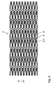
- Figure 1 shows the development of the jacket of a preferred embodiment of the stent 1 according to the invention with a number of annular support sections 2 from web elements 3, which in the longitudinal direction of the stent 1 via connecting webs 4 are connected.
- the one in the unwound state thin-walled, tubular component formed sheath of the stent 1 is with others Words formed like a network.
- the web elements 3 and the Connecting webs 4 are from the remaining wall of the tubular Component formed.
- the annular support portions 2 are each one in the circumferential direction of the stent 1 formed meandering web element 3.
- the connecting bars 4 between a first annular support section of 2.1 and a second annular support section 2.2 each engage in the area of a first direction 5 projecting portions of the web elements 3 of the first annular support section 2.1.
- the connecting webs 4 are also in relation to the longitudinal direction of the stent 1 lines 6 running along the longitudinal direction of the stent 1 mutually so arranged that the end point or point of attack lying in the first direction 5 a first connecting web 4.1 during the expansion of the stent 1 an angle change is impressed that is opposite to the angle change is the end point or point of attack lying in the first direction 5 a second connecting web 4.2 adjacent in the first direction 5 is imprinted.
- This ensures that the annular support sections 2 of the stent 1 during its expansion to each other in its circumferential direction twist, but these twists over the length of the Compensate for stents 1. This ensures that the stent 1 during expansion undergoes no significant twisting over its length.
- the twist is the example shown by the chosen symmetrical design and arrangement of the connecting webs 4 completely excluded. It is understood, however, that in other embodiments of the invention Stents also other, asymmetrical designs and arrangements of the connecting webs can be provided if there is a corresponding one with these Compensation of the twists of the annular support sections results.
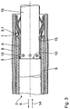
- FIG 2 shows schematically the stent 1 of Figure 1 in a partial section on a Catheter 7, which is inserted into a blood vessel 8.
- the stent 1 is there in the area of a constriction 8.1 of this blood vessel 8, which is widened by it shall be.
- the stent 1 is shown in its first state in FIG which he is completely in a sheath of the catheter 7, the a sheath tube 9 arranged at the distal end of the catheter 7 is formed.
- the stent 1 is in a reduced diameter compressed state, so that due to elastic restoring forces acting in it presses radially outwards against the inner wall of the cladding tube 9.
- the stent 1 is arranged on a holder 10.
- the cladding tube 9 and the holder 10 are slidably arranged to each other.
- an end cap 11 Located at the distal end of the holder 10 an end cap 11, which closes the cladding tube 9 in the state shown, to facilitate the insertion of the stent 1 into the blood vessel 8. It it goes without saying, however, that this end cap in other variants of the invention Catheters need not necessarily be provided.
- the holder 10 has projections 12 which at the proximal end of the Stents 1, the web elements 3 in the region of the 5 pointing in the first direction Reach behind turning points 3.1. Furthermore, the holder 10 has a shoulder 13 on, which acts as a stop for the stent 1 in the area of the turning points 3.1 serves.
- the cladding tube 9 can of the holder 10 and thus also with respect to the stent 1 in the first direction 5 withdrawn.
- the stop 13 prevents the biased stent 1 with the cladding tube against the inner wall of the cladding tube 9 9 is moved in the first direction 5.
- the areas of the stent 1 that are covered by the Removing the cladding tube 9 is no longer compressed to the reduced diameter are held, expand immediately.
- the Stent 1 expands over its entire length and is therefore in its second state.
- Figure 3 shows a further partial section through the embodiment of Figure 2 in one State of the stent 1, in which the cladding tube 9 is partially removed from the stent 1, d. H. withdrawn in the first direction 5 with respect to the stent 1.
- the sections of the stent 1 that are outside the cladding tube 9 are already largely expanded to their final diameter. Only in the area that directly adjacent to the distal end of the cladding tube 9, takes place in the longitudinal direction of the stent 1 a slow transition from the compressed diameter to the expanded diameter instead.
- a correction step can now be carried out be carried out in which the partially expanded stent again in its first State is reset and then its position is corrected. It understands that this method is not necessarily in vivo, i. H. on the patient must be executed. It can also be in vitro, i.e. H. on any other Vessels or the like are executed.
- the stent 1 is reset by the cladding tube 9 relative to the holder 10 by means of a device on the proximal, not shown in FIGS. 2 and 3 End of the catheter 7 in an opposite direction to the first direction second direction 14 is pushed over the stent 1 again.
- the design and arrangement of the web elements 3 and the connecting webs 4 ensures that there is no jamming of the protruding in the first direction 5 Sections, i.e. the turning points protruding in the first direction 5 3.1 of the web elements 3 at the extending, distal end of the cladding tube 9 can come.
- the connecting webs 4 ensure that the in the first direction protruding turning points 3.1 of the web elements 3 at Pushing the cladding tube 9 over the stent 1 in the directly to the leading End of the cladding tube 9 adjacent area of the stent 1 so far be pulled radially inwards that the cladding tube 9 without snagging over the 5 portions of the web elements 3 projecting in the first direction slide can.
- the smooth pushing of the cladding tube 9 is still done by a chamfer 15 at the distal end of the cladding tube 9 supports.
- the connecting webs 4 engage directly in the area the turning points 3.1 of the web elements 3 pointing in the first direction 5 on.
- the connecting webs 4 directly on the furthest in the first direction 5 projecting section of the respective web element 3 on.
- the connecting webs in others Designs of the stent according to the invention are not necessarily on this most protruding section of the respective in the first direction Must attack the web element. You can also use one less in their area section of the respective web element projecting far in the first direction attack. In other words, the point of attack of each Connecting bridge in the first direction from adjacent sections of the Bridge elements are still towered over.
- Figure 4 shows the development of the jacket of another embodiment of the stents according to the invention. Its basic structure is the same as that from Figure 1, so that only the differences are discussed here should.
- connecting webs 4 ' are not immediately connected the closest turning point 3.1 'of the web element in the longitudinal direction of the stent 1' 3 'attack, but on a circumferential direction of the stent 1' offset turning point 3.1 '.
- This increases the length of the connecting webs 4 'compared to the embodiment from Figure 1, which in turn leads to an increase the flexibility of the stent 1 'leads with respect to its longitudinal direction.
- the stents from FIGS. 1 to 4 each consist of a shape memory alloy based on nickel-titanium, so-called nitinol.
- This stent material is at body temperature in the first state of the stent 1, that is, in its in the cladding tube 9 compressed state, in a stress-induced martensitic Status. In the second state, i.e. largely relaxed state of the stent 1, it is in an austenitic state.
- the stent 1 is in an initial state which is in the corresponds essentially to the expanded final state, at a temperature which is below body temperature and at which it is in a martensitic Condition is so plastically deformed, d. H.
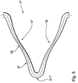
- FIG. 5 shows the development of a section of a web element 3 "in accordance with a preferred embodiment of the stent according to the invention. Act here too it is made of one of the shape memory alloys described above.
- the stent from FIG. 5 can essentially be the stent from FIG Figures 1 to 4 correspond, so that here only the special features of the Web elements to be entered
- the peculiarity of the web element 3 is that, on the one hand, its geometry is selected and on the other hand the width of the web element 3 "over its Length varies such that the tensions that occur in it when the Stent material in the first state of the stent 1 "due to an increase in temperature from the martensitic state to a stress-induced martensitic Condition passes below that prevailing at the respective temperature remain plastic deformation limit of the stent material.
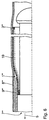
- FIG 6 shows a partial section through a further embodiment of an inventive Stents on a catheter 7 '' 'according to the invention in the partially expanded Status.
- the catheter 7 '' ' essentially corresponds to the catheter from Figures 2 and 3, so here only the differences with respect of the stent 1 '' '.
- the stent 1 '' 'prevents snagging the web elements 3 '' 'on the cladding tube 9' '' when returning to its first state is provided with a casing 19.
- This casing 19 is like this formed that, on the one hand, the expansion of the stent 1 '' 'into its desired Final state enables.
- the sheath 19 has an adequate circumferential direction of the stent Elasticity, which the expansion of the stent essentially does not with special needs.
- it in the longitudinal direction of the stent, it has a low one Elasticity to the above pre-deformation in the immediately attached to the free end of the area of the stent 1 '' 'adjacent to the sheath at its Ensure return to the first state.
- this is realized by a film 19 made of a correspondingly elastic plastic, in the corresponding tensile fibers running in the longitudinal direction of the stent are embedded are.
- the tensile fibers run in the area of the 5 '' 'in the first direction. projecting sections of the web elements 3 '' '.
- the web elements are in this area 3 '' ' also connected to the film 19 to ensure an even application of force to ensure or a sliding of the fibers from these areas of To prevent force application.
- the second substance can consist of one or more components with none of the components of the first substance is or are the same.
- the second substance can equally well correspond to a component of the first substance.
- the first substance is built up from a matrix in which the first Substance is embedded, for example, the second substance from which the matrix constituent component of the first substance or correspond to this.
Landscapes
- Health & Medical Sciences (AREA)
- Engineering & Computer Science (AREA)
- Biomedical Technology (AREA)
- Heart & Thoracic Surgery (AREA)
- Optics & Photonics (AREA)
- Cardiology (AREA)
- Oral & Maxillofacial Surgery (AREA)
- Transplantation (AREA)
- Physics & Mathematics (AREA)
- Vascular Medicine (AREA)
- Life Sciences & Earth Sciences (AREA)
- Animal Behavior & Ethology (AREA)
- General Health & Medical Sciences (AREA)
- Public Health (AREA)
- Veterinary Medicine (AREA)
- Media Introduction/Drainage Providing Device (AREA)
Applications Claiming Priority (2)
| Application Number | Priority Date | Filing Date | Title |
|---|---|---|---|
| DE10044043 | 2000-08-30 | ||
| DE10044043A DE10044043A1 (de) | 2000-08-30 | 2000-08-30 | Reponierbarer Stent |
Publications (2)
| Publication Number | Publication Date |
|---|---|
| EP1184007A2 true EP1184007A2 (fr) | 2002-03-06 |
| EP1184007A3 EP1184007A3 (fr) | 2004-03-31 |
Family
ID=7655269
Family Applications (1)
| Application Number | Title | Priority Date | Filing Date |
|---|---|---|---|
| EP01250302A Withdrawn EP1184007A3 (fr) | 2000-08-30 | 2001-08-23 | Stent à tension optimale |
Country Status (3)
| Country | Link |
|---|---|
| US (2) | US20020049487A1 (fr) |
| EP (1) | EP1184007A3 (fr) |
| DE (1) | DE10044043A1 (fr) |
Cited By (11)
| Publication number | Priority date | Publication date | Assignee | Title |
|---|---|---|---|---|
| WO2006138548A1 (fr) | 2005-06-15 | 2006-12-28 | Med Institute, Inc. | Dispositif intraluminal a pieces de soutien coniques asymetriques |
| WO2006138547A1 (fr) | 2005-06-15 | 2006-12-28 | Med Institute, Inc | Dispositif intraluminal a pieces de soutien coniques perfectionnees |
| EP2158880A1 (fr) * | 2008-08-26 | 2010-03-03 | Cordis Corporation | Endoprothèse intravasculaire dotée d'un design amélioré pour le chargement et le déploiement |
| EP2040643A4 (fr) * | 2006-07-13 | 2011-08-17 | Icon Medical Corp | Stent |
| EP2567678A1 (fr) * | 2004-05-21 | 2013-03-13 | Conor Medsystems, Inc. | Endoprothèse vasculaire avec éléments de pontage profilés |
| US8808618B2 (en) | 2005-03-03 | 2014-08-19 | Icon Medical Corp. | Process for forming an improved metal alloy stent |
| WO2016110875A1 (fr) * | 2015-01-07 | 2016-07-14 | Sahajanand Medical Technologies Private Limited | Endoprothèse endoluminale |
| CN109640882A (zh) * | 2016-08-23 | 2019-04-16 | 深圳市信立泰生物医疗工程有限公司 | 一种植入式完全生物可吸收血管聚合物支架 |
| CN116407371A (zh) * | 2021-12-31 | 2023-07-11 | 先健科技(深圳)有限公司 | 管腔支架 |
| US11766506B2 (en) | 2016-03-04 | 2023-09-26 | Mirus Llc | Stent device for spinal fusion |
| US11779685B2 (en) | 2014-06-24 | 2023-10-10 | Mirus Llc | Metal alloys for medical devices |
Families Citing this family (49)
| Publication number | Priority date | Publication date | Assignee | Title |
|---|---|---|---|---|
| US6395019B2 (en) | 1998-02-09 | 2002-05-28 | Trivascular, Inc. | Endovascular graft |
| AU2002360765C1 (en) | 2001-12-20 | 2009-06-11 | Trivascular, Inc. | Advanced endovascular graft |
| US7147661B2 (en) * | 2001-12-20 | 2006-12-12 | Boston Scientific Santa Rosa Corp. | Radially expandable stent |
| US6989024B2 (en) * | 2002-02-28 | 2006-01-24 | Counter Clockwise, Inc. | Guidewire loaded stent for delivery through a catheter |
| DE10213369A1 (de) * | 2002-03-21 | 2003-10-02 | Biotronik Mess & Therapieg | Stent |
| US7316710B1 (en) * | 2002-12-30 | 2008-01-08 | Advanced Cardiovascular Systems, Inc. | Flexible stent |
| ATE446065T1 (de) * | 2003-03-18 | 2009-11-15 | Veryan Medical Ltd | Spiralförmiger stent |
| DE602004027353D1 (de) * | 2003-03-18 | 2010-07-08 | Veryan Medical Ltd | Platzierungsvorrichtung für eine prothese auf einer körperröhre |
| GB0306176D0 (en) | 2003-03-18 | 2003-04-23 | Imp College Innovations Ltd | Tubing |
| DE10323628A1 (de) | 2003-05-20 | 2004-12-30 | Biotronik Ag | Stents aus einem Material geringer Bruchdehnung |
| US20080264102A1 (en) | 2004-02-23 | 2008-10-30 | Bolton Medical, Inc. | Sheath Capture Device for Stent Graft Delivery System and Method for Operating Same |
| US11259945B2 (en) | 2003-09-03 | 2022-03-01 | Bolton Medical, Inc. | Dual capture device for stent graft delivery system and method for capturing a stent graft |
| US7763063B2 (en) | 2003-09-03 | 2010-07-27 | Bolton Medical, Inc. | Self-aligning stent graft delivery system, kit, and method |
| US9198786B2 (en) | 2003-09-03 | 2015-12-01 | Bolton Medical, Inc. | Lumen repair device with capture structure |
| US20070198078A1 (en) | 2003-09-03 | 2007-08-23 | Bolton Medical, Inc. | Delivery system and method for self-centering a Proximal end of a stent graft |
| US8292943B2 (en) * | 2003-09-03 | 2012-10-23 | Bolton Medical, Inc. | Stent graft with longitudinal support member |
| US11596537B2 (en) | 2003-09-03 | 2023-03-07 | Bolton Medical, Inc. | Delivery system and method for self-centering a proximal end of a stent graft |
| US8500792B2 (en) | 2003-09-03 | 2013-08-06 | Bolton Medical, Inc. | Dual capture device for stent graft delivery system and method for capturing a stent graft |
| US7803178B2 (en) | 2004-01-30 | 2010-09-28 | Trivascular, Inc. | Inflatable porous implants and methods for drug delivery |
| CA2558573A1 (fr) * | 2004-03-11 | 2005-09-22 | Trivascular, Inc. | Greffon endovasculaire modulaire |
| DE102004022044B4 (de) * | 2004-05-03 | 2008-12-18 | Qualimed Innovative Medizinprodukte Gmbh | Stent |
| US7303580B2 (en) * | 2004-07-26 | 2007-12-04 | Cook Incorporated | Stent delivery system allowing controlled release of a stent |
| US9107899B2 (en) | 2005-03-03 | 2015-08-18 | Icon Medical Corporation | Metal alloys for medical devices |
| US20070198076A1 (en) * | 2006-02-13 | 2007-08-23 | Stephen Hebert | System for delivering a stent |
| US8298278B2 (en) * | 2006-03-07 | 2012-10-30 | Boston Scientific Scimed, Inc. | Bifurcated stent with improvement securement |
| US8348991B2 (en) * | 2006-03-29 | 2013-01-08 | Boston Scientific Scimed, Inc. | Stent with overlap and high expansion |
| US8043358B2 (en) * | 2006-03-29 | 2011-10-25 | Boston Scientific Scimed, Inc. | Stent with overlap and high extension |
| US20080255654A1 (en) * | 2007-03-22 | 2008-10-16 | Bay Street Medical | System for delivering a stent |
| US20080300667A1 (en) * | 2007-05-31 | 2008-12-04 | Bay Street Medical | System for delivering a stent |
| US9144508B2 (en) | 2007-07-19 | 2015-09-29 | Back Bay Medical Inc. | Radially expandable stent |
| US8226701B2 (en) | 2007-09-26 | 2012-07-24 | Trivascular, Inc. | Stent and delivery system for deployment thereof |
| US8066755B2 (en) | 2007-09-26 | 2011-11-29 | Trivascular, Inc. | System and method of pivoted stent deployment |
| US8663309B2 (en) | 2007-09-26 | 2014-03-04 | Trivascular, Inc. | Asymmetric stent apparatus and method |
| AU2008308474B2 (en) | 2007-10-04 | 2014-07-24 | Trivascular, Inc. | Modular vascular graft for low profile percutaneous delivery |
| US8328861B2 (en) | 2007-11-16 | 2012-12-11 | Trivascular, Inc. | Delivery system and method for bifurcated graft |
| US8083789B2 (en) | 2007-11-16 | 2011-12-27 | Trivascular, Inc. | Securement assembly and method for expandable endovascular device |
| JP5484458B2 (ja) | 2008-06-30 | 2014-05-07 | ボルトン メディカル インコーポレイテッド | 腹部大動脈瘤システム |
| US9597214B2 (en) | 2008-10-10 | 2017-03-21 | Kevin Heraty | Medical device |
| AU2010223953B2 (en) | 2009-03-13 | 2014-05-01 | Bolton Medical, Inc. | System and method for deploying an endoluminal prosthesis at a surgical site |
| US8398916B2 (en) | 2010-03-04 | 2013-03-19 | Icon Medical Corp. | Method for forming a tubular medical device |
| US8992595B2 (en) | 2012-04-04 | 2015-03-31 | Trivascular, Inc. | Durable stent graft with tapered struts and stable delivery methods and devices |
| US9498363B2 (en) | 2012-04-06 | 2016-11-22 | Trivascular, Inc. | Delivery catheter for endovascular device |
| BR112014025430A2 (pt) | 2012-04-12 | 2020-03-10 | Bolton Medical, Inc. | Dispositivo de envio protético vascular e método de uso |
| US9439751B2 (en) | 2013-03-15 | 2016-09-13 | Bolton Medical, Inc. | Hemostasis valve and delivery systems |
| DE102018105925A1 (de) * | 2018-03-14 | 2019-09-19 | Malte Neuss | Doppelstent |
| CA3125220A1 (fr) * | 2019-01-11 | 2020-07-16 | Oregon Health & Science University | Endoprotheses auxetiques pour la prise en charge de la stenose veineuse |
| EP4171449B1 (fr) | 2020-06-24 | 2026-03-04 | Bolton Medical, Inc. | Composant anti-retour pour dispositif de pose de prothèse vasculaire |
| CN114504411B (zh) * | 2020-10-29 | 2024-12-31 | 上海加奇生物科技苏州有限公司 | 一种支架 |
| CN112155658B (zh) * | 2020-10-29 | 2022-03-18 | 上海加奇生物科技苏州有限公司 | 取栓支架和血栓抓捕器 |
Citations (1)
| Publication number | Priority date | Publication date | Assignee | Title |
|---|---|---|---|---|
| EP0657147A2 (fr) | 1993-11-04 | 1995-06-14 | C.R. Bard, Inc. | Prothèse vasculaire non migrante et son système d'implantation peu agressif |
Family Cites Families (29)
| Publication number | Priority date | Publication date | Assignee | Title |
|---|---|---|---|---|
| US7204848B1 (en) * | 1995-03-01 | 2007-04-17 | Boston Scientific Scimed, Inc. | Longitudinally flexible expandable stent |
| DE19512066A1 (de) * | 1995-04-01 | 1996-11-28 | Variomed Ag | Stütze (Stent, Prothese) für kanalikuläre Körperstrukturen, z. B. Blutgefäße, Gallengänge, Speise- und Luftröhre |
| ES2131253T3 (es) * | 1995-11-14 | 1999-07-16 | Schneider Europ Gmbh | Dispositivo para la implantacion de una endoprotesis. |
| US6203569B1 (en) * | 1996-01-04 | 2001-03-20 | Bandula Wijay | Flexible stent |
| IL117472A0 (en) * | 1996-03-13 | 1996-07-23 | Instent Israel Ltd | Radiopaque stent markers |
| CA2252596C (fr) * | 1996-04-26 | 2006-06-13 | Scimed Life Systems, Inc. | Prothese endovasculaire |
| US6241760B1 (en) * | 1996-04-26 | 2001-06-05 | G. David Jang | Intravascular stent |
| US5697971A (en) * | 1996-06-11 | 1997-12-16 | Fischell; Robert E. | Multi-cell stent with cells having differing characteristics |
| WO1998040035A1 (fr) * | 1997-03-13 | 1998-09-17 | United States Surgical Corporation | Dispositif de support de tissu flexible |
| FR2764794B1 (fr) * | 1997-06-20 | 1999-11-12 | Nycomed Lab Sa | Dispositif tubulaire expanse a epaisseur variable |
| DE69838256T2 (de) * | 1997-09-24 | 2008-05-15 | Med Institute, Inc., West Lafayette | Radial aufweitbarer stent |
| US5972027A (en) * | 1997-09-30 | 1999-10-26 | Scimed Life Systems, Inc | Porous stent drug delivery system |
| DE19753123B4 (de) * | 1997-11-29 | 2006-11-09 | B. Braun Melsungen Ag | Gefäßstütze |
| US6190406B1 (en) * | 1998-01-09 | 2001-02-20 | Nitinal Development Corporation | Intravascular stent having tapered struts |
| US6503271B2 (en) * | 1998-01-09 | 2003-01-07 | Cordis Corporation | Intravascular device with improved radiopacity |
| US6129755A (en) * | 1998-01-09 | 2000-10-10 | Nitinol Development Corporation | Intravascular stent having an improved strut configuration |
| US6179867B1 (en) * | 1998-01-16 | 2001-01-30 | Advanced Cardiovascular Systems, Inc. | Flexible stent and method of use |
| US6533807B2 (en) * | 1998-02-05 | 2003-03-18 | Medtronic, Inc. | Radially-expandable stent and delivery system |
| US6066169A (en) * | 1998-06-02 | 2000-05-23 | Ave Connaught | Expandable stent having articulated connecting rods |
| US6261319B1 (en) * | 1998-07-08 | 2001-07-17 | Scimed Life Systems, Inc. | Stent |
| FR2781143B1 (fr) * | 1998-07-17 | 2000-11-10 | Braun Celsa Sa | Support expansible a meandres pour un conduit anatomique,en particulier, un vaisseau sanguin |
| US6461380B1 (en) * | 1998-07-28 | 2002-10-08 | Advanced Cardiovascular Systems, Inc. | Stent configuration |
| DE19840645A1 (de) * | 1998-09-05 | 2000-03-09 | Jomed Implantate Gmbh | Stent |
| ES2373028T3 (es) * | 1998-11-20 | 2012-01-30 | Boston Scientific Limited | Stent expandible longitudinalmente flexible. |
| DE19900411A1 (de) * | 1999-01-08 | 2000-07-13 | Lothar Sellin | Stent |
| DE19906956B4 (de) * | 1999-02-19 | 2011-07-21 | QualiMed Innovative Medizin-Produkte GmbH, 21423 | Stent sowie Verfahren zur Herstellung eines Stents |
| US6730116B1 (en) * | 1999-04-16 | 2004-05-04 | Medtronic, Inc. | Medical device for intraluminal endovascular stenting |
| DE19951607A1 (de) * | 1999-10-26 | 2001-05-10 | Biotronik Mess & Therapieg | Stent mit geschlossener Struktur |
| US6540775B1 (en) * | 2000-06-30 | 2003-04-01 | Cordis Corporation | Ultraflexible open cell stent |
-
2000
- 2000-08-30 DE DE10044043A patent/DE10044043A1/de not_active Withdrawn
-
2001
- 2001-08-23 EP EP01250302A patent/EP1184007A3/fr not_active Withdrawn
- 2001-08-24 US US09/939,057 patent/US20020049487A1/en not_active Abandoned
- 2001-08-24 US US09/939,211 patent/US20020095140A1/en not_active Abandoned
Patent Citations (1)
| Publication number | Priority date | Publication date | Assignee | Title |
|---|---|---|---|---|
| EP0657147A2 (fr) | 1993-11-04 | 1995-06-14 | C.R. Bard, Inc. | Prothèse vasculaire non migrante et son système d'implantation peu agressif |
Cited By (14)
| Publication number | Priority date | Publication date | Assignee | Title |
|---|---|---|---|---|
| EP2567678A1 (fr) * | 2004-05-21 | 2013-03-13 | Conor Medsystems, Inc. | Endoprothèse vasculaire avec éléments de pontage profilés |
| US8808618B2 (en) | 2005-03-03 | 2014-08-19 | Icon Medical Corp. | Process for forming an improved metal alloy stent |
| US8574285B2 (en) | 2005-06-15 | 2013-11-05 | Cook Medical Technologies Llc | Intraluminal device with improved tapered beams |
| AU2006259293B2 (en) * | 2005-06-15 | 2011-03-10 | Cook Medical Technologies Llc | Intraluminal device with unsymmetric tapered beams |
| WO2006138548A1 (fr) | 2005-06-15 | 2006-12-28 | Med Institute, Inc. | Dispositif intraluminal a pieces de soutien coniques asymetriques |
| WO2006138547A1 (fr) | 2005-06-15 | 2006-12-28 | Med Institute, Inc | Dispositif intraluminal a pieces de soutien coniques perfectionnees |
| EP2040643A4 (fr) * | 2006-07-13 | 2011-08-17 | Icon Medical Corp | Stent |
| EP2158880A1 (fr) * | 2008-08-26 | 2010-03-03 | Cordis Corporation | Endoprothèse intravasculaire dotée d'un design amélioré pour le chargement et le déploiement |
| US11779685B2 (en) | 2014-06-24 | 2023-10-10 | Mirus Llc | Metal alloys for medical devices |
| WO2016110875A1 (fr) * | 2015-01-07 | 2016-07-14 | Sahajanand Medical Technologies Private Limited | Endoprothèse endoluminale |
| US10722389B2 (en) | 2015-01-07 | 2020-07-28 | Sahajanand Medical Technologies Private Limited | Endoluminal stent |
| US11766506B2 (en) | 2016-03-04 | 2023-09-26 | Mirus Llc | Stent device for spinal fusion |
| CN109640882A (zh) * | 2016-08-23 | 2019-04-16 | 深圳市信立泰生物医疗工程有限公司 | 一种植入式完全生物可吸收血管聚合物支架 |
| CN116407371A (zh) * | 2021-12-31 | 2023-07-11 | 先健科技(深圳)有限公司 | 管腔支架 |
Also Published As
| Publication number | Publication date |
|---|---|
| US20020049487A1 (en) | 2002-04-25 |
| EP1184007A3 (fr) | 2004-03-31 |
| DE10044043A1 (de) | 2002-03-14 |
| US20020095140A1 (en) | 2002-07-18 |
Similar Documents
| Publication | Publication Date | Title |
|---|---|---|
| EP1184007A2 (fr) | Stent à tension optimale | |
| DE69101385T2 (de) | Selbstausdehnbare prothese mit stabiler axialer länge. | |
| DE60002480T2 (de) | Stenteinbringungssystem | |
| EP0749290B1 (fr) | Extenseur destine a etre place dans un vaisseau du corps | |
| DE3342798C2 (fr) | ||
| EP1023008B1 (fr) | Extenseur elargi et son procede de fabrication | |
| DE69831935T2 (de) | Bistabiler federaufbau für ein stent | |
| DE60309843T2 (de) | Vorrichtung zur verankerung von endoluminalprothesen | |
| DE69924400T2 (de) | Endoluminales gewebe mit kontinuierlich kurvenlinearen drahtformen | |
| DE69723941T2 (de) | Selbstexpandierende Endoprothese | |
| DE69829494T2 (de) | Nachgiebige intraluminale stents | |
| DE3250058C2 (fr) | ||
| EP0746269B1 (fr) | Extenseur destine a etre place dans un vaisseau du corps | |
| DE69733111T2 (de) | Kompositstent | |
| DE69732992T2 (de) | Stent mit variablen Eigenschaften zur Stützoptimierung | |
| EP0481365B1 (fr) | Dispositif pour dilater une sténose dans un conduit corporel | |
| DE69728083T2 (de) | Stentanordnung | |
| DE69508592T2 (de) | Vorrichtung zur Stentimplantierung | |
| DE69228260T2 (de) | Impregnierter stent | |
| DE69434509T2 (de) | Stent | |
| DE69727004T2 (de) | Ein Stent für Angioplastie | |
| DE69729633T2 (de) | Implantierbare vorrichtung zum festerhalten oder wiederherstellen eines normalen körpergefässquerschnittes | |
| DE19938377A1 (de) | Stent für Gefässverzweigungen | |
| DE202011107781U1 (de) | Prothesenanordnung zur Implantation in oder um ein Hohlorgan | |
| WO2014202645A1 (fr) | Endoprothèse |
Legal Events
| Date | Code | Title | Description |
|---|---|---|---|
| PUAI | Public reference made under article 153(3) epc to a published international application that has entered the european phase |
Free format text: ORIGINAL CODE: 0009012 |
|
| AK | Designated contracting states |
Kind code of ref document: A2 Designated state(s): AT BE CH CY DE DK ES FI FR GB GR IE IT LI LU MC NL PT SE TR |
|
| AX | Request for extension of the european patent |
Free format text: AL;LT;LV;MK;RO;SI |
|
| PUAL | Search report despatched |
Free format text: ORIGINAL CODE: 0009013 |
|
| AK | Designated contracting states |
Kind code of ref document: A3 Designated state(s): AT BE CH CY DE DK ES FI FR GB GR IE IT LI LU MC NL PT SE TR |
|
| AX | Request for extension of the european patent |
Extension state: AL LT LV MK RO SI |
|
| 17P | Request for examination filed |
Effective date: 20040930 |
|
| AKX | Designation fees paid |
Designated state(s): AT BE CH CY DE DK ES FI FR GB GR IE IT LI LU MC NL PT SE TR |
|
| STAA | Information on the status of an ep patent application or granted ep patent |
Free format text: STATUS: THE APPLICATION IS DEEMED TO BE WITHDRAWN |
|
| 18D | Application deemed to be withdrawn |
Effective date: 20060202 |