EP1184123A1 - Numerisch gesteuerte funkenerosionsbohrmaschine - Google Patents
Numerisch gesteuerte funkenerosionsbohrmaschine Download PDFInfo
- Publication number
- EP1184123A1 EP1184123A1 EP00118198A EP00118198A EP1184123A1 EP 1184123 A1 EP1184123 A1 EP 1184123A1 EP 00118198 A EP00118198 A EP 00118198A EP 00118198 A EP00118198 A EP 00118198A EP 1184123 A1 EP1184123 A1 EP 1184123A1
- Authority
- EP
- European Patent Office
- Prior art keywords
- electrode
- guide
- axis
- spindle
- length
- Prior art date
- Legal status (The legal status is an assumption and is not a legal conclusion. Google has not performed a legal analysis and makes no representation as to the accuracy of the status listed.)
- Withdrawn
Links
- 238000003860 storage Methods 0.000 claims description 32
- 238000000034 method Methods 0.000 claims description 25
- 238000012545 processing Methods 0.000 claims description 15
- 238000005259 measurement Methods 0.000 claims description 10
- 230000003287 optical effect Effects 0.000 claims description 10
- 238000005553 drilling Methods 0.000 claims description 9
- 238000003754 machining Methods 0.000 claims description 4
- 239000002184 metal Substances 0.000 claims description 2
- 229910052751 metal Inorganic materials 0.000 claims description 2
- 238000006073 displacement reaction Methods 0.000 claims 1
- 238000007599 discharging Methods 0.000 description 6
- 125000004122 cyclic group Chemical group 0.000 description 3
- 238000004519 manufacturing process Methods 0.000 description 3
- 238000013459 approach Methods 0.000 description 2
- 238000010276 construction Methods 0.000 description 2
- 238000013461 design Methods 0.000 description 2
- 238000001514 detection method Methods 0.000 description 2
- 229910000851 Alloy steel Inorganic materials 0.000 description 1
- 229910000881 Cu alloy Inorganic materials 0.000 description 1
- 238000010586 diagram Methods 0.000 description 1
- 238000003780 insertion Methods 0.000 description 1
- 230000037431 insertion Effects 0.000 description 1
- JEIPFZHSYJVQDO-UHFFFAOYSA-N iron(III) oxide Inorganic materials O=[Fe]O[Fe]=O JEIPFZHSYJVQDO-UHFFFAOYSA-N 0.000 description 1
- 239000003550 marker Substances 0.000 description 1
- 239000000463 material Substances 0.000 description 1
- 238000011076 safety test Methods 0.000 description 1
- 230000000007 visual effect Effects 0.000 description 1
- XLYOFNOQVPJJNP-UHFFFAOYSA-N water Substances O XLYOFNOQVPJJNP-UHFFFAOYSA-N 0.000 description 1
Images


Classifications
-
- B—PERFORMING OPERATIONS; TRANSPORTING
- B23—MACHINE TOOLS; METAL-WORKING NOT OTHERWISE PROVIDED FOR
- B23H—WORKING OF METAL BY THE ACTION OF A HIGH CONCENTRATION OF ELECTRIC CURRENT ON A WORKPIECE USING AN ELECTRODE WHICH TAKES THE PLACE OF A TOOL; SUCH WORKING COMBINED WITH OTHER FORMS OF WORKING OF METAL
- B23H9/00—Machining specially adapted for treating particular metal objects or for obtaining special effects or results on metal objects
- B23H9/14—Making holes
-
- B—PERFORMING OPERATIONS; TRANSPORTING
- B23—MACHINE TOOLS; METAL-WORKING NOT OTHERWISE PROVIDED FOR
- B23H—WORKING OF METAL BY THE ACTION OF A HIGH CONCENTRATION OF ELECTRIC CURRENT ON A WORKPIECE USING AN ELECTRODE WHICH TAKES THE PLACE OF A TOOL; SUCH WORKING COMBINED WITH OTHER FORMS OF WORKING OF METAL
- B23H7/00—Processes or apparatus applicable to both electrical discharge machining and electrochemical machining
- B23H7/26—Apparatus for moving or positioning electrode relatively to workpiece; Mounting of electrode
- B23H7/265—Mounting of one or more thin electrodes
Definitions
- CNC EDM Drill In processing those dies or parts used in the area like computer parts manufacturing, aircraft engine manufacturing, medical equipments or supplies fully automated production is a requirement or a must for this type of processing.
- the present invention relates to a CNC EDM Drill, and more particularly to one comprised of an electrode capable of sensing its length, replacing, storing and selecting an electrode guide to achieve fully automated and continuous operation of hole discharge processing (drilling) on work pieces of different thickness and hole size.
- Electrodes currently available in the market feature that:
- the "preparative operation” may take three to five minutes, and longer in case of changing to guide for different size of electrode.
- the discharging time for each hole takes like thirty to sixty seconds. For example, given with a 25 mm-thick work piece of steel alloy at 1 mm/sec of processing rate, the discharging time approximately takes less than 30 seconds. In this case, the time taken to prepare is 3 to 5 time of the processing time.
- the "preparative operation" flow is described as follows:
- the first purpose of the present invention is to provide a CNC EDM Drill which contains means to detect the processing electrode or measure its length, and to engage in continuous and automated process two or more than two holes in the same hole size with the same electrode.
- Another purpose of the present invention is to provide a CNC EDM Drill, containing further a means for automated exchange of the electrode.
- the consumed electrode or the electrode with a length not sufficient for the next round of process is automatically replaced with a new one to ensure the continuous and automated processing on two or more than two holes of the same size.
- Another purpose yet of the present invention is to provide a CNC EDM Drill, containing further a means for selecting an electrode guide so to continuously and automatically process holes of different sizes.
- the preferred embodiment of the present invention is related to a CNC EDM Drill (1) supplying each section (or each block) to the machine.
- the break down of these blocks is comprised of the following sections:
- Preparing section°F Preparative operation is automatically completed during the preparing section (a pre-requisition of fully automated operation of EDM drilling), an operation essentially using the means of Electrode Detecting (2) of the preferred embodiment of the present invention.
- the electrode length and wear are known for a specific hole before starting the machine to carry on discharging working automatically.
- the length measurement section it allows automated measurement of the length of electrode, corresponding to electrode length measurement (3) of the preferred embodiment of the present invention.
- This section not only achieves the preparative operation, but also eliminates the estimation and the input for Z-axis (Z) retracting (after finishing one hole) and whether the residual length is sufficient for the next hole. Once the residual length of the electrode is not sufficient for the next hole, it will be automatically moved to another machining position, or go to replacing section to be described below. While running out of electrode under drilling a hole, it permits also automatically selecting another electrode to continue that hole because of knowing the electrode length both of the used one and new one.
- Replacing section allows automated replacement of electrode, corresponding to an automatic electrode replacing method (4) and an electrode storage device (44) of the preferred embodiment of the present invention, thus to complete automatic and continuous processing to the multiple of holes in the same hole-size on the work piece.
- the guide selection section corresponding to an electrode guide selection device (5) of the preferred embodiment of the present invention if a proper electrode guide will be selected so to complete automatic and continuous processing to the multiple holes in the different diameter on the same work piece.
- the preferred embodiment of the CNC EDM Drill (1) is comprised of the following parts:
- An Electrode Detecting (2) block contains optical detecting (21) and a conductivity sensing (22) categories.
- the optical detecting (21) further contains background reflecting (211) or background reflection removing (212) feasible means
- the Conductivity Sensing (22) category detects conductivity changing, including touch work piece (221), detecting dielectric level (222), touch auxiliary plate (223) or touch guide (224) feasible means.
- An electrode length measurement (3) contains the same method and means as those provided with the electrode detecting (2), but further apply at the right time.
- Touch work piece (221) has a non-consistency danger that when the surface of customer supplied work piece getting rusted by water normally worked as dielectric. Proper electrical condition must be selected to discharge the rust away and not to damage the surface when using this means is necessary.
- means in conductivity sensing category are applicable as long as the electrode is protruded from the guide by a proper length. By design, for any given state only one of the feasible means shall be enough.
- An electrode replacing method (4) contains two keys: By taking advantage of clockwise or counter-clockwise turning of the spindle (41), and by taking advantage of Z-axis movement (42) of the machine or an elastic member (4412) to absorb the length created upon tightening or loosening a collet nut (B1).
- An electrode storage device (44) derived from the electrode replacing method (4) contains an electrode storage unit (441) and an electrode carrousel (442) (comprised of a multiple of the electrode storage devices and other components). By design, the carrousel (442) may be made mobile or fixed to a console.
- An electrode guide selection device (5) is essentially comprised of a rotating plate (55) connected with multiple guide units that can be rotated in position.
- the optical detecting (21) category of electrode detecting (2) block includes the background reflecting (211) and background reflection removing (212) feasible means. Once the light emits toward an object for measurement, the light will be reflected from the object and picked up by receiver. If the volume of the object to be measured is large enough, and bright enough to reflect sufficient amount of light, the comparison method by teaching will work. However, in case of the width of the electrode is less than 0.5 mm, or the glaze of the electrode is poor, e.g., a darkened electrode, or in case of an electrode in diameter of 0.1 mm that yields weak reflection amount, then the reflection from the background must be eliminated to the minimal to ensure correct detecting.
- the background reflecting (211) means operates based on comparing the incoming light amount with the amount reflected by a certain object (e.g. the electrode) and background that were teach on the machine in advance.
- the light is first projected to the background and certainly will be reflected since there are other objects in the background (particularly so true with a machine where a console or other mechanical parts are present).
- the amount of the light reflected by the background is stored as a reference value M0.
- a value, M1 is obtained from the amount of light reflected from the object to be measured. Compare incoming light with M1 and M0 values to judge whether the electrode has been detected. This comparison method is workable for a newer or thicker electrode.
- the background reflection removing means (212) is provided to make sure that the background reflects the minimum amount of light or does not reflect any light at all.
- a reflector (2123) (such as in the form of a very bright mirror) is provided and placed at a proper angle (e.g. 45 degrees) to the direction of the detecting light beam (2122) to eliminate the light beam otherwise to be reflected from the background to the detector to keep M0 as low as possible.
- the M0 measured by an optical sensor (2121) is practically reduced to a very a small value, the difference between M0 and M1 becomes meaningfully large for the incoming light comparison. Therefore, as long as incoming light approaches M1, it indicates the electrode (P) does pass through. Thus the length of the electrode may be measured at any time.
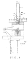
- the optical sensor (2121) may be provided on the electrode storage unit (441) (Fig. 4) to be described later.
- An opening (4416) is provided on the electrode storage unit (441) to make sure that there is no object to reflect the light from the background, so that the lowest M0 is also achieved.
- the category of conductivity sensing (22) operates according to changes of conductivity under various situations. It may include touch work piece (221), detecting dielectric level (222), touch auxiliary plate (223) and touch guide (224) feasible means.
- the sensing method by the touch work piece (221) is to introduce non-working current into residual electrode to detect signals from the work piece disengaging from the end of the residual electrode. Said signals then are used as the data for the preparative operation in the subsequent machining.
- the original length of the electrode is set at L0, and L1, the parameter of Z-axis position of the spindle is memorized upon commencing the discharge working once the electrode chucked by the spindle descends to where closing to the work piece.
- the working current is changed to safety test current (non-working current) upon completing the hole drilling, and the electrode detecting means detects electrode chucked by the spindle is clearing away from the work piece, and records L2, the Z-axis position parameter of said spindle.
- the method of detecting dielectric level (222) will be used to detect.
- the dielectric is injected into the electrode beforehand and the level shall cover up the upper level of the work piece.
- Parameters L11 and L12 respectively measured by having the electrode to touch or clear away from the working dielectric level are used to substitute L1 and L2.
- auxiliary metal plate is paved in advance on the bottom of the work piece.
- Parameter L22 replaces L2 (with L1 not changed) once the electrode goes the work piece to touch the auxiliary plate after the course of drilling.
- touch guide (224) means, a current at amperage not damaging the mechanical parts is first conducted into the electrode before the processing. Then the electrode descends to the guide provided on the W-axis, so that the shaking electrode will have to touch the guide where signals are outputted. By controlling the electrode to such extent that it sticks out of the guide for a proper length. Such position is used as the start point for the computation to allow the electrode to lower for an extra 2 ⁇ 3 mm, thus to automatically complete the preparative operation.
- Electrode replacing method (4) and the electrode storage device (44) are described as follows:
- the electrode replacing method (4) for the EDM Drill includes the clockwise or count-clockwise turning of the spindle on the machine (41) so that the Z-axis moves to absorb change in the length of said spindle (42) [or an elastic member is sued to absorb the change in the length of the collet nut (B1)].
- the electrode storage device (44) comprised of an electrode storage unit (441) and a carousel (442), is the preferred embodiment of said exchanging method.
- the electrode storage units (441) are provided in proper quantity, and the collet nut (B1) properly chucking the electrode is stored in the electrode storage unit (441), which then is placed at or transferred to a position reachable in case of either of X-axis or Y-axis moves.
- the spindle is moved to where above the electrode storage unit (441).
- the spindle (B) turns either clockwise or counter-clockwise and the Z-axis moves longitudinally so to combine or release the collet nut (B1), in turn, fetching for the use or unloading the electrode vertically.
- the electrode storage unit (441) of the present invention relates to a rigid member (4411) comprised of an elastic member (4412) to absorb change in length resulted from combining or releasing the collet nut (B1) by the spindle (B), and a holder (4413) to store and restrict the rotation by the collet nut (B1).
- the holder (4413) of the collet nut (B1) can be provided at the upper end of a frame (4411) while a concave that can hold local profile of the collet nut (B1) is provided on the holder (4413).
- the elastic member (4412) is provided below the frame (4411) (not illustrated in the accompanying drawings). Additional electrode guarding duct (4414) may be provided in proper quantity on the frame (4411) and a through-hole (not illustrated in the accompanying drawings) in upside-down cone shape is formed inside the electrode-guarding duct (4414).
- the collet nut (B1) as illustrated in Fig. 3 has its nut (B11) containing a collet (B12) and the collet (B12) chucks both of the electrode (P) and its leak-proof seal (P1) so to directly contain said nut (B11) in the holder (4413).
- female threads (B111) inside the nut (B11) can be bolted to those male threads (B2) provided at the lower end of the spindle (B) to tighten up or loosen up.
- Fig. 4 shows the cutaway view of chucking the electrode (P).
- the spindle (B) descends until it holds against both of the nut (B11) of the collet nut (B1) and the holder (4413)[The nut (B11) contains the collet (B12), the electrode (P), and the seal (P1)] to press against the holder (4413). So the holder (4413) descends and compresses the elastic member (4412) to a proper position but not all way down to the end. Simultaneously, the spindle (B) turns clockwise to engage both of the collet nut (B1) and the spindle (B) while chucking tightly the collet (B12).
- the seal (P1) is pressed and the electrode properly chucked. Meanwhile, the elastic member (4412) pushes back the holder (4413) for the holder (4413) to maintain restricting the nut (B11) from rotating until it is screwed into the spindle (B).
- both of the spindle (B) and its collet nut (B1) are descending to where the nut (B11) merely presses against and descend the holder (4413) until the nut (B11) clears away from the spindle (B).
- the elastic member (4412) absorbs the change in length of the releasing nut (B11).
- the preferred embodiment of a complete CNC system of the present invention is comprised of the electrode storage device (44) and the electrode guide selection device (5) (also refer to Figs. 8 and 9).
- the electrode storage device (44) is comprised of a multiple of electrode storage unit (441) and other components to form a mobile electrode carousel (442), which is connected to engage in cyclic movement.
- the preferred embodiment also contains a W-axis (W) operating on the existing X-axis (X), or Y-axis (Y) of the machine and the spindle (B). Within, said X-axis (X) extends itself to become an extended X-axis (X').
- a cyclic connection conveyer (4421) for the electrode carousel (442) is of cyclic chains.
- the electrode detecting (2) [and length measurement (3), within, as illustrated, the background reflection removing (212) of the optical detecting (21) means is applied] under normal condition, the nut (B11), the collet (B12), the electrode (P) and leak-proof seal (P1) are provided to each electrode storage unit (441).
- said spindle (B) must be empty [i.e. not screwed with a nut (B11)], otherwise, at least one set of the electrode storage unit (441) must be left empty for the entire system.
- the electrode storage carousel (442) may deliver a single storage unit (441) in cycle to a designated point in position while the W-axis (W) moves at the X-axis (X), or Y-axis (Y) and the extended X-axis (X') to where above the electrode (P).
- the W-axis (W) also moves longitudinally along the Z-axis and the spindle (B) turns clockwise or counter-clockwise to fetch or unload the electrode (P).
- the length measurement means (3) [detecting means with background reflection removing (212)] is used to measure the length of the electrode (P).
- the electrode guide selection device (5) turns to select the guide unit (56) with a proper size for the insertion by the electrode (P).
- the preferred embodiment of the guide select means of the present invention is comprised of encoder (51), motor (52), brake (53), gear (54), rotating plate (55), proper quantity of guide unit (56), home position plate (57).
- the encoder (51) gives the turning angles of the rotating plate (55) or the motor (52).
- the brake (53) is used to restrict the gear (54), but said brake (53) may be unnecessary in case of that the gear ration is greater than a certain value (e.g. 20:1).
- the gear (54) is fixed to the rotating plate (55) while the circumference of said rotating plate (55) is used to hold the guide unit (56) in position.
- the home position plate (57) is fixed to the turning shaft of the motor (52) for both to synchronously rotate.
- a mark (571) is protruding from the home position plate (57) and is detected by a sensor (572) in a cycle of rotation by the home position plate (57).
- Fig. 10 shows the detailed construction of the guide unit (56).
- the guide unit (56) is comprised of fixation plate (561), slide (562), guide holder (563), guide (564) and hopper (565).
- fixation plate (561) and the slide (562) Refer to Figs. 8 and 9 for the fixation plate (561) and the slide (562).
- An oval opening (not illustrated) is provided below the fixation plate (561)(not illustrated) for a bolt (5611) to go through and fix to the rotating plate (55) and for inching the relative position between the guide unit (56) and the rotating plate (55).
- a dovetail (5612) is provided to the fixation plate (561) so to relatively caulk to each other with the slide (562) while inching their relative positions.
- the slide (562) is further connected with a bolt (5633) to the guide holder (563) whereupon the guide (564) is provided.
- Grooves (5631) in proper quantity are provided on the guide holder (563), and also bolting holes (5632) and bolts (5633) in proper quantity are provided on the guide holder (563).
- the grooves (5631) are in parallel on a horizontal plane while the bolting holes (5632) are at a right angle to the grooves (5631) and bolted to bolts (5633).
- more than one set of guide unit (56) may be provided on the rotating plate (55) and the encoder (51) may be used to give the rotating plate (55) or the motor (52) for automated control the rotation angle of the rotating plate (55), thus the guide to the guide unit (56) required can be turned to stop at a proper position for the electrode (P) descending along the Z-axis (Z) to pass through the guide (564) and achieve the purpose of selecting the desired guide (564).
- the reference point in the preferred embodiment is defined by the mark (571) of the home position plate (57).
Landscapes
- Engineering & Computer Science (AREA)
- Mechanical Engineering (AREA)
- Physics & Mathematics (AREA)
- Thermal Sciences (AREA)
- Chemical & Material Sciences (AREA)
- Chemical Kinetics & Catalysis (AREA)
- Electrochemistry (AREA)
- Electrical Discharge Machining, Electrochemical Machining, And Combined Machining (AREA)
- Pharmaceuticals Containing Other Organic And Inorganic Compounds (AREA)
- Luminescent Compositions (AREA)
- Numerical Control (AREA)
Priority Applications (9)
| Application Number | Priority Date | Filing Date | Title |
|---|---|---|---|
| EP05015155A EP1649961B1 (de) | 2000-08-31 | 2000-08-31 | Numerisch gesteuerte Funkenerosionsbohrmaschine |
| DE60037152T DE60037152D1 (de) | 2000-08-31 | 2000-08-31 | Numerisch gesteuerte Funkenerosionsbohrmaschine |
| AT05015154T ATE378135T1 (de) | 2000-08-31 | 2000-08-31 | Numerisch gesteuerte funkenerosionsbohrmaschine |
| EP05015154A EP1649960B1 (de) | 2000-08-31 | 2000-08-31 | Numerisch gesteuerte Funkenerosionsbohrmaschine |
| DE60033708T DE60033708T2 (de) | 2000-08-31 | 2000-08-31 | Numerisch gesteuerte Funkenerosionsbohrmaschine |
| ES05015155T ES2282957T3 (es) | 2000-08-31 | 2000-08-31 | Maquina de taladrar por electroerosion, con control numerico. |
| EP00118198A EP1184123A1 (de) | 2000-08-31 | 2000-08-31 | Numerisch gesteuerte funkenerosionsbohrmaschine |
| AT05015155T ATE355148T1 (de) | 2000-08-31 | 2000-08-31 | Numerisch gesteuerte funkenerosionsbohrmaschine |
| DK05015155T DK1649961T5 (da) | 2000-08-31 | 2000-08-31 | Cnc edm bor |
Applications Claiming Priority (1)
| Application Number | Priority Date | Filing Date | Title |
|---|---|---|---|
| EP00118198A EP1184123A1 (de) | 2000-08-31 | 2000-08-31 | Numerisch gesteuerte funkenerosionsbohrmaschine |
Related Child Applications (2)
| Application Number | Title | Priority Date | Filing Date |
|---|---|---|---|
| EP05015154A Division EP1649960B1 (de) | 2000-08-31 | 2000-08-31 | Numerisch gesteuerte Funkenerosionsbohrmaschine |
| EP05015155A Division EP1649961B1 (de) | 2000-08-31 | 2000-08-31 | Numerisch gesteuerte Funkenerosionsbohrmaschine |
Publications (1)
| Publication Number | Publication Date |
|---|---|
| EP1184123A1 true EP1184123A1 (de) | 2002-03-06 |
Family
ID=8169621
Family Applications (3)
| Application Number | Title | Priority Date | Filing Date |
|---|---|---|---|
| EP00118198A Withdrawn EP1184123A1 (de) | 2000-08-31 | 2000-08-31 | Numerisch gesteuerte funkenerosionsbohrmaschine |
| EP05015154A Expired - Lifetime EP1649960B1 (de) | 2000-08-31 | 2000-08-31 | Numerisch gesteuerte Funkenerosionsbohrmaschine |
| EP05015155A Expired - Lifetime EP1649961B1 (de) | 2000-08-31 | 2000-08-31 | Numerisch gesteuerte Funkenerosionsbohrmaschine |
Family Applications After (2)
| Application Number | Title | Priority Date | Filing Date |
|---|---|---|---|
| EP05015154A Expired - Lifetime EP1649960B1 (de) | 2000-08-31 | 2000-08-31 | Numerisch gesteuerte Funkenerosionsbohrmaschine |
| EP05015155A Expired - Lifetime EP1649961B1 (de) | 2000-08-31 | 2000-08-31 | Numerisch gesteuerte Funkenerosionsbohrmaschine |
Country Status (5)
| Country | Link |
|---|---|
| EP (3) | EP1184123A1 (de) |
| AT (2) | ATE378135T1 (de) |
| DE (2) | DE60037152D1 (de) |
| DK (1) | DK1649961T5 (de) |
| ES (1) | ES2282957T3 (de) |
Cited By (6)
| Publication number | Priority date | Publication date | Assignee | Title |
|---|---|---|---|---|
| EP1541272A3 (de) * | 2003-12-11 | 2005-11-23 | ROLLS-ROYCE plc | Vorrichtung und Verfahren zum Funkenerosionsbohren |
| CN100406182C (zh) * | 2005-09-14 | 2008-07-30 | 台一电子机械股份有限公司 | 细孔放电加工机的电极管储存方法与装置 |
| EP3290142A1 (de) * | 2016-08-30 | 2018-03-07 | Agie Charmilles SA | Verfahren und messvorrichtung zur ermittlung des elektrodenverschleisses beim funkerodieren |
| EP3297784A4 (de) * | 2015-05-19 | 2018-08-15 | Johnson Technology, Inc. | Automatischer elektrodenwechsler für funkenerosionsbearbeitung |
| CN113490569A (zh) * | 2019-02-12 | 2021-10-08 | 赛峰飞机发动机公司 | 在由导电材料制成的部件中钻销孔的方法 |
| US11932838B2 (en) | 2014-11-25 | 2024-03-19 | Corning Incorporated | Cell culture media extending materials and methods |
Families Citing this family (1)
| Publication number | Priority date | Publication date | Assignee | Title |
|---|---|---|---|---|
| CN102554378B (zh) * | 2012-01-12 | 2013-05-22 | 中国工程物理研究院机械制造工艺研究所 | 一种多功能复合电加工主轴 |
Citations (4)
| Publication number | Priority date | Publication date | Assignee | Title |
|---|---|---|---|---|
| JPH08290332A (ja) * | 1995-04-18 | 1996-11-05 | Erenitsukusu:Kk | 細穴放電加工機に対する電極、電極ガイド交換方法及び同方法に使用する交換装置、電極ホルダ、細穴放電加工機 |
| JPH09174341A (ja) * | 1995-12-20 | 1997-07-08 | Makino Milling Mach Co Ltd | 放電加工機 |
| DE19804371A1 (de) * | 1997-02-04 | 1998-08-13 | Mitsubishi Electric Corp | Funkenerosionsmaschine für kleine Löcher und Funkenerosionsverfahren unter Verwendung einer derartigen Maschine |
| WO2000023222A1 (fr) * | 1998-10-16 | 2000-04-27 | Astec Co., Ltd. | Procede et dispositif pour remplacer une electrode tubulaire pendant la gravure par etincelage de petits trous, et magasin a electrodes |
Family Cites Families (3)
| Publication number | Priority date | Publication date | Assignee | Title |
|---|---|---|---|---|
| JP3161687B2 (ja) * | 1995-11-14 | 2001-04-25 | 株式会社牧野フライス製作所 | 電極ガイド自動交換装置を備えた放電加工機 |
| DE29715782U1 (de) * | 1997-09-03 | 1997-12-11 | Abacus Automatisierungstechnik GmbH, 49080 Osnabrück | Elektrodenwechsler für Funkenerosionsmaschinen, insbesondere funkenerosive Bohrmaschinen |
| US6933456B2 (en) * | 2003-10-09 | 2005-08-23 | Elenix, Inc. | Small hole electrical discharge machining method and small hole electrical discharge machining apparatus and electrode inserting method and electrode inserting apparatus |
-
2000
- 2000-08-31 AT AT05015154T patent/ATE378135T1/de not_active IP Right Cessation
- 2000-08-31 EP EP00118198A patent/EP1184123A1/de not_active Withdrawn
- 2000-08-31 AT AT05015155T patent/ATE355148T1/de not_active IP Right Cessation
- 2000-08-31 DE DE60037152T patent/DE60037152D1/de not_active Expired - Lifetime
- 2000-08-31 EP EP05015154A patent/EP1649960B1/de not_active Expired - Lifetime
- 2000-08-31 DE DE60033708T patent/DE60033708T2/de not_active Expired - Lifetime
- 2000-08-31 ES ES05015155T patent/ES2282957T3/es not_active Expired - Lifetime
- 2000-08-31 EP EP05015155A patent/EP1649961B1/de not_active Expired - Lifetime
- 2000-08-31 DK DK05015155T patent/DK1649961T5/da active
Patent Citations (4)
| Publication number | Priority date | Publication date | Assignee | Title |
|---|---|---|---|---|
| JPH08290332A (ja) * | 1995-04-18 | 1996-11-05 | Erenitsukusu:Kk | 細穴放電加工機に対する電極、電極ガイド交換方法及び同方法に使用する交換装置、電極ホルダ、細穴放電加工機 |
| JPH09174341A (ja) * | 1995-12-20 | 1997-07-08 | Makino Milling Mach Co Ltd | 放電加工機 |
| DE19804371A1 (de) * | 1997-02-04 | 1998-08-13 | Mitsubishi Electric Corp | Funkenerosionsmaschine für kleine Löcher und Funkenerosionsverfahren unter Verwendung einer derartigen Maschine |
| WO2000023222A1 (fr) * | 1998-10-16 | 2000-04-27 | Astec Co., Ltd. | Procede et dispositif pour remplacer une electrode tubulaire pendant la gravure par etincelage de petits trous, et magasin a electrodes |
Non-Patent Citations (2)
| Title |
|---|
| PATENT ABSTRACTS OF JAPAN vol. 1997, no. 03 31 March 1997 (1997-03-31) * |
| PATENT ABSTRACTS OF JAPAN vol. 1997, no. 11 28 November 1997 (1997-11-28) * |
Cited By (9)
| Publication number | Priority date | Publication date | Assignee | Title |
|---|---|---|---|---|
| EP1541272A3 (de) * | 2003-12-11 | 2005-11-23 | ROLLS-ROYCE plc | Vorrichtung und Verfahren zum Funkenerosionsbohren |
| CN100406182C (zh) * | 2005-09-14 | 2008-07-30 | 台一电子机械股份有限公司 | 细孔放电加工机的电极管储存方法与装置 |
| US11932838B2 (en) | 2014-11-25 | 2024-03-19 | Corning Incorporated | Cell culture media extending materials and methods |
| EP3297784A4 (de) * | 2015-05-19 | 2018-08-15 | Johnson Technology, Inc. | Automatischer elektrodenwechsler für funkenerosionsbearbeitung |
| EP3479945A1 (de) * | 2015-05-19 | 2019-05-08 | Johnson Technology, Inc. | Automatischer elektrodenwechsler für funkenerosionsbearbeitung |
| EP3290142A1 (de) * | 2016-08-30 | 2018-03-07 | Agie Charmilles SA | Verfahren und messvorrichtung zur ermittlung des elektrodenverschleisses beim funkerodieren |
| CN113490569A (zh) * | 2019-02-12 | 2021-10-08 | 赛峰飞机发动机公司 | 在由导电材料制成的部件中钻销孔的方法 |
| CN113490569B (zh) * | 2019-02-12 | 2023-12-08 | 赛峰飞机发动机公司 | 在由导电材料制成的部件中钻销孔的方法 |
| US12151296B2 (en) | 2019-02-12 | 2024-11-26 | Safran Aircraft Engines | Method for drilling a hole in a part made of electroconductive material |
Also Published As
| Publication number | Publication date |
|---|---|
| EP1649960A1 (de) | 2006-04-26 |
| DK1649961T3 (da) | 2007-07-02 |
| ES2282957T3 (es) | 2007-10-16 |
| DE60033708D1 (de) | 2007-04-12 |
| DE60033708T2 (de) | 2007-11-15 |
| DK1649961T5 (da) | 2007-08-13 |
| EP1649961A1 (de) | 2006-04-26 |
| ATE355148T1 (de) | 2006-03-15 |
| ATE378135T1 (de) | 2007-11-15 |
| EP1649961B1 (de) | 2007-02-28 |
| DE60037152D1 (de) | 2007-12-27 |
| EP1649960B1 (de) | 2007-11-14 |
Similar Documents
| Publication | Publication Date | Title |
|---|---|---|
| CN106475854B (zh) | 具有加工精度维持功能的加工系统 | |
| CA1090108A (en) | Unmanned machining center with tool checking | |
| EP0712687A1 (de) | Verfahren und Vorrichtung zur Zuführung von Werkzeugmaschinenkühlflüssigkeiten | |
| EP1649961B1 (de) | Numerisch gesteuerte Funkenerosionsbohrmaschine | |
| US20200130120A1 (en) | Machine tool and gear machining method | |
| JP5728931B2 (ja) | ワーク搬送装置 | |
| KR101357507B1 (ko) | 심공 가공 방법 및 심공 가공 장치 | |
| EP0714053B1 (de) | Steuerungsverfahren und -vorrichtung zum Erkennen von Spananhäufung | |
| JP4947534B2 (ja) | 工作機械及び工作機械を操作する方法 | |
| US4266120A (en) | Unmanned machining center with tool checking | |
| JP2021039058A (ja) | ねじ軸測定方法、並びにねじ軸測定装置及びこれを備えたnc工作機械 | |
| JP2017222018A (ja) | 工作機械及び工作機械による加工方法 | |
| JP2021037601A (ja) | 収容装置及びこれを備えた複合加工機械 | |
| CN114054783B (zh) | 一种实轴制造自动化的模块组合生产工艺 | |
| US20050119781A1 (en) | Detecting breakages in machine tools and the like | |
| JP3097295U (ja) | 細穴放電加工機 | |
| JPS6361602B2 (de) | ||
| JP3097295U6 (ja) | 細穴放電加工機 | |
| JPH0871805A (ja) | 心押軸の移動制御および着座確認装置 | |
| JP2001030143A (ja) | ボールエンドミル工具の自動測定方法および自動測定装置 | |
| JPS6026658B2 (ja) | 工作機械の刃具交換装置 | |
| EP2644319A1 (de) | Werkzeugmaschine und Verfahren zur Ermittlung einer Geometrie eines Werkstücks | |
| JPH04171162A (ja) | 旋盤におけるバイト摩耗検査・補正方法及びその装置 | |
| JP2005046944A (ja) | 工作機械の熱変位補正方法およびその装置 | |
| JPH04504983A (ja) | 工具ホルダー及び急速回転スピンドル |
Legal Events
| Date | Code | Title | Description |
|---|---|---|---|
| PUAI | Public reference made under article 153(3) epc to a published international application that has entered the european phase |
Free format text: ORIGINAL CODE: 0009012 |
|
| AK | Designated contracting states |
Kind code of ref document: A1 Designated state(s): AT BE CH CY DE DK ES FI FR GB GR IE IT LI LU MC NL PT SE |
|
| AX | Request for extension of the european patent |
Free format text: AL;LT;LV;MK;RO;SI |
|
| 17P | Request for examination filed |
Effective date: 20020408 |
|
| AKX | Designation fees paid |
Free format text: AT BE CH CY DE DK ES FI FR GB GR IE IT LI LU MC NL PT SE |
|
| 17Q | First examination report despatched |
Effective date: 20050317 |
|
| STAA | Information on the status of an ep patent application or granted ep patent |
Free format text: STATUS: THE APPLICATION IS DEEMED TO BE WITHDRAWN |
|
| 18D | Application deemed to be withdrawn |
Effective date: 20050930 |