EP1184131A1 - Dispositif d'appui pour machine à forer, en particulier pour plaquettes de circuits imprimés - Google Patents
Dispositif d'appui pour machine à forer, en particulier pour plaquettes de circuits imprimés Download PDFInfo
- Publication number
- EP1184131A1 EP1184131A1 EP01119849A EP01119849A EP1184131A1 EP 1184131 A1 EP1184131 A1 EP 1184131A1 EP 01119849 A EP01119849 A EP 01119849A EP 01119849 A EP01119849 A EP 01119849A EP 1184131 A1 EP1184131 A1 EP 1184131A1
- Authority
- EP
- European Patent Office
- Prior art keywords
- pressure
- drilling
- worktable
- activated
- supporting member
- Prior art date
- Legal status (The legal status is an assumption and is not a legal conclusion. Google has not performed a legal analysis and makes no representation as to the accuracy of the status listed.)
- Withdrawn
Links
- 238000005553 drilling Methods 0.000 title claims abstract description 49
- 238000003754 machining Methods 0.000 claims abstract description 20
- 230000033001 locomotion Effects 0.000 claims abstract description 6
- 230000005540 biological transmission Effects 0.000 claims description 2
- 238000003825 pressing Methods 0.000 claims 2
- 239000011159 matrix material Substances 0.000 description 3
- 238000010586 diagram Methods 0.000 description 1
- 238000004519 manufacturing process Methods 0.000 description 1
Images

Classifications
-
- B—PERFORMING OPERATIONS; TRANSPORTING
- B23—MACHINE TOOLS; METAL-WORKING NOT OTHERWISE PROVIDED FOR
- B23Q—DETAILS, COMPONENTS, OR ACCESSORIES FOR MACHINE TOOLS, e.g. ARRANGEMENTS FOR COPYING OR CONTROLLING; MACHINE TOOLS IN GENERAL CHARACTERISED BY THE CONSTRUCTION OF PARTICULAR DETAILS OR COMPONENTS; COMBINATIONS OR ASSOCIATIONS OF METAL-WORKING MACHINES, NOT DIRECTED TO A PARTICULAR RESULT
- B23Q3/00—Devices holding, supporting, or positioning work or tools, of a kind normally removable from the machine
- B23Q3/002—Means to press a workpiece against a guide
-
- B—PERFORMING OPERATIONS; TRANSPORTING
- B25—HAND TOOLS; PORTABLE POWER-DRIVEN TOOLS; MANIPULATORS
- B25B—TOOLS OR BENCH DEVICES NOT OTHERWISE PROVIDED FOR, FOR FASTENING, CONNECTING, DISENGAGING OR HOLDING
- B25B11/00—Work holders not covered by any preceding group in the subclass, e.g. magnetic work holders, vacuum work holders
- B25B11/002—Magnetic work holders
-
- H—ELECTRICITY
- H05—ELECTRIC TECHNIQUES NOT OTHERWISE PROVIDED FOR
- H05K—PRINTED CIRCUITS; CASINGS OR CONSTRUCTIONAL DETAILS OF ELECTRIC APPARATUS; MANUFACTURE OF ASSEMBLAGES OF ELECTRICAL COMPONENTS
- H05K3/00—Apparatus or processes for manufacturing printed circuits
- H05K3/0011—Working of insulating substrates or insulating layers
- H05K3/0044—Mechanical working of the substrate, e.g. drilling or punching
- H05K3/0047—Drilling of holes
-
- H—ELECTRICITY
- H05—ELECTRIC TECHNIQUES NOT OTHERWISE PROVIDED FOR
- H05K—PRINTED CIRCUITS; CASINGS OR CONSTRUCTIONAL DETAILS OF ELECTRIC APPARATUS; MANUFACTURE OF ASSEMBLAGES OF ELECTRICAL COMPONENTS
- H05K2203/00—Indexing scheme relating to apparatus or processes for manufacturing printed circuits covered by H05K3/00
- H05K2203/02—Details related to mechanical or acoustic processing, e.g. drilling, punching, cutting, using ultrasound
- H05K2203/0278—Flat pressure, e.g. for connecting terminals with anisotropic conductive adhesive
Definitions
- the present invention relates to a workholder system for a drilling machine, in particular for printed circuit boards.
- Advanced electronics and computer industries employ an enormous number of printed circuit boards, the processing of which comprises drilling a large number of holes or microholes.
- the boards are formed into packs, each comprising two plates for supporting and positioning the pack on the drilling machine worktable; and the boards in the pack are drilled simultaneously by a drill fitted to a rotating spindle in turn fitted to the machining head.
- the worktable and machining head are movable with respect to each other to select the drilling point on the pack; and the spindle is movable towards the worktable to impart forward motion to the drill, and is normally provided with a workholder device for engaging the board pack prior to engagement by the drill, and for securing the pack to the worktable during the drilling operation.
- the workholder device is normally defined by a ring having two lateral arms connected to the machining head by elastic pressure means, such as springs or fluidic cylinders, so that each machining head must be fitted with a specific workholder device and is invariably complex and expensive.
- a workholder system for a drilling machine comprising a fixed frame; a worktable; at least one tool spindle; positioning means for moving said spindle and said worktable with respect to each other in two coordinate directions to select a drilling point on the work; feed means activated to move said spindle through a drilling stroke; and workholder means activated to secure the work to said worktable during drilling; characterized in that said workholder means are carried by said frame and are activated independently of said feed means.
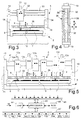
- Number 5 in Figure 1 indicates as a whole a printed circuit board drilling machine, which substantially comprises a fixed frame 6; a worktable 7 to which a pack 8 of printed circuit boards for drilling is fixed in known manner; and a rotating tool spindle 9 fitted with a drill 11.
- the holes in printed circuit boards are normally arranged in a matrix of rows and columns.
- spindle 9 is fitted to a machining head 12 fixed to frame 6, and has feed means, comprising an electric servomotor 13, for moving spindle 9 towards worktable 7 through a drilling stroke along the usual Z axis.
- Machine 5 also comprises positioning means for moving spindle 9 and worktable 7 with respect to each other in two coordinate directions, or along two coordinate axes, X and Y to select the drilling point on pack 8.
- worktable 7 is movable with respect to frame 6 along two perpendicular guides; the positioning means comprise two electric servomotors 14 and 15 for controlling movement along axes X and Y respectively; and servomotors 13, 14 and 15 are controlled, e.g. feedback controlled, by a known electronic control unit 16 on the basis of a pack 8 drilling program.
- machine 5 is equipped with a workholder system comprising workholder means 17, which are activated to clamp pack 8 to worktable 7 during drilling, are carried by fixed frame 6, and are activated independently of feed means of spindle 9.
- workholder means 17 comprise a supporting member 18 connected adjustably to frame 6, e.g. by known devices 19 for adjusting the distance between supporting member 18 and worktable 7.
- Supporting member 18 supports a pressure member 22 having a circular opening 21 aligned with spindle 9. Between supporting member 18 and pressure member 22 are provided actuating means 23, which may be defined by a fluidic device, e.g. comprising a compressed-air cylinder 24 fixed to member 18, and a piston 25 fixed to member 22.
- actuating means 23 which may be defined by a fluidic device, e.g. comprising a compressed-air cylinder 24 fixed to member 18, and a piston 25 fixed to member 22.
- the Figure 1 embodiment comprises two devices 24-25 diametrically opposite with respect to the axis of spindle 9 and activated under the control of electronic control unit 16 to cause pressure member 22 clamp pack 8 to worktable 7.
- the Figure 1 workholder system operates as follows.
- control unit 16 is operated to first activate servomotors 14 and 15 to align with drill 11 on spindle 9 the point on pack 8 where the first hole is to be drilled, and then activate compressed-air devices 24-25 followed by servomotor 13.
- Pistons 25 therefore bring pressure member 22 into contact with pack 8, which is thus pressed elastically on worktable 7, before pack 8 is engaged by drill 11; and servomotor 13 feeds spindle 9 forward to drill pack 8 to the programmed depth.
- Pressure member 22 maintains the clamping pressure on pack 8 throughout the drilling operation, regardless of the axial position of spindle 9. And, once drilling is completed, control unit 16 reverses servomotor 13 so that spindle 9 withdraws drill 11 from pack 8; activates devices 24-25 so that member 22 releases pack 8; and again activates servomotors 14 and 15 to select the next drilling point.
- actuating means 23 operating pressure member 22 may be defined by electromagnetic, magnetostrictive or piezoelectric means controlled in known manner by unit 16, in which case, the workholder system operates in the same way as described above.
- the workholder system as a whole defined by supporting member 18, pressure member 22 and actuating means 23, forms part of drilling machine 5, as opposed to machining head 12 of spindle 9. Since the same drilling machine 5 can be fitted with heads 12 mounting different spindles 9, depending on the size of tools 11 used, and since machining head 12 with spindle 9 is a delicate, high-cost assembly with a shorter life than drilling machine 5, the advantage of the workholder system forming part of machine 5, as opposed to machining head 12, is obvious.
- the workholder supporting member is in the form of a plate 28 also connected to fixed frame 6 by distance-adjusting devices, and having at least two pressure members 29 connected individually to respective actuating means, e.g. to two electromagnets 30, by respective motion transmission means. More specifically, each member 29 is carried by a respective lever 31 activated by respective electromagnet 30 and designed to produce a predetermined force-travel ratio of respective pressure member 29 on pack 8.
- the two pressure members 29 may be located at the same or different distances from the axis of tool 11.
- control unit 16 energizes electromagnets 30 simultaneously; in the second case, control unit 16 selects and energizes, each time, the electromagnet 30 controlling the pressure member 29 closest to the drilling point on pack 8, e.g. the one on the right in Figure 2.
- spindle 9 and worktable 7 are performed by spindle 9 and worktable 7 respectively. More specifically, spindle 9 is supported on a carriage 32 moved by the X-axis servomotor 14 along a cross member 33 fitted to two uprights 34 of fixed frame 6 of drilling machine 5; and worktable 7 is moved in one direction by the Y-axis servomotor 15.
- the workholder system advantageously comprises a plate 36 connected to the two uprights 34 by two distance-adjusting devices 19; and plate 36 has a central opening 38 ( Figure 4) aligned with the plane in which the axis of spindle 9 travels along the X axis, so as to form two bars 39 supporting two parallel rows of pressure members, e.g. the same as pressure members 29 in Figure 2.
- drilling is programmed to first set worktable 7 to a row in the hole matrix, carriage 32 of spindle 9 is moved sequentially to select the various drilling points along that row, and control unit 16 is programmed to select the pair of pressure members 29 closest to the drilling point.
- drilling machine 5 has a number of spindles 9 fitted to respective machining heads 12a, 12b, ..., 12n running independently along a common cross member 41 fixed to two lateral uprights 42; and worktable 7 supports a number of packs 8 of circuit boards, normally equal to the number of spindles 9 on cross member 41, and is movable perpendicularly to cross member 41, as in Figure 3.
- the workholder system advantageously comprises a plate 36 forming two bars 39 and connected to the two uprights 42 by two adjusting devices 19; and plate 36 has an opening 38 ( Figure 4) forming two bars 39 supporting two parallel rows of pressure members 29.
- Control unit 16 may be defined by a microprocessor 43 associated with a RAM 44 and a ROM 45, and which receives, over an input bus 46, signals indicating the position of worktable 7 and the various machining heads 12a, 12b, ..., 12n, and, over an output bus 47, controls respective servomotors 15, 14a, 14b, ..., 14n and 13a, 13b, ... 13n, and selects and controls the various pairs of pressure members 29a, 29b, ..., 29n.
- Drilling is programmed on microprocessor 43 to first set worktable 7 to a row in the matrix, and each spindle 9 is moved sequentially over respective pack 8 to select the various points in that row for drilling in respective pack 8.
- microprocessor 43 is programmed to select, for each machining head 12a, 12b, ..., 12n, the pair of pressure members 29a, 29b, ..., 29n closest to the drilling point, throughout the time respective tool 11 engages respective pack 8.
- spindles 9 on cross member 41 may all be fitted to a common carriage and so perform the same drilling program.
- the workholder system may comprise two pairs of bars 39 corresponding to the two rows of spindles 9.
- microprocessor 43 is programmed to select, for each machining head 12a, 12b, ..., 12n, the pair of pressure members 29a, 29b, ..., 29n closest to the respective drilling point.
- microprocessor 43 may be programmed to activate, for each hole to be drilled, a different number of pressure members 29 adjacent to each drilling point.
Landscapes
- Engineering & Computer Science (AREA)
- Mechanical Engineering (AREA)
- Manufacturing & Machinery (AREA)
- Microelectronics & Electronic Packaging (AREA)
- Drilling And Boring (AREA)
Applications Claiming Priority (2)
| Application Number | Priority Date | Filing Date | Title |
|---|---|---|---|
| ITTO000829 | 2000-08-30 | ||
| IT2000TO000829A IT1320611B1 (it) | 2000-08-30 | 2000-08-30 | Sistema premipezzo per una macchina foratrice, in particolare perschede di circuiti stampati. |
Publications (1)
| Publication Number | Publication Date |
|---|---|
| EP1184131A1 true EP1184131A1 (fr) | 2002-03-06 |
Family
ID=11458015
Family Applications (1)
| Application Number | Title | Priority Date | Filing Date |
|---|---|---|---|
| EP01119849A Withdrawn EP1184131A1 (fr) | 2000-08-30 | 2001-08-16 | Dispositif d'appui pour machine à forer, en particulier pour plaquettes de circuits imprimés |
Country Status (2)
| Country | Link |
|---|---|
| EP (1) | EP1184131A1 (fr) |
| IT (1) | IT1320611B1 (fr) |
Cited By (7)
| Publication number | Priority date | Publication date | Assignee | Title |
|---|---|---|---|---|
| WO2007049324A1 (fr) * | 2005-10-28 | 2007-05-03 | Lg Technologies S.R.L. | Dispositif de perçage de vitesse elevee de cartes de circuits imprimes et similaire |
| CN1824460B (zh) * | 2005-02-24 | 2011-06-29 | Lpkf激光和电子股份公司 | 用于确定铣削工具的位置的方法和实施此方法的加工头 |
| US8070400B2 (en) | 2005-10-28 | 2011-12-06 | Lg Technologies S.R.L. | Device for the high-speed drilling of printed circuit boards |
| WO2014120345A1 (fr) * | 2013-01-31 | 2014-08-07 | The Boeing Company | Procédé et appareil pour le perçage multiple automatisé et machine à rivets multiples |
| CN106142205A (zh) * | 2015-04-22 | 2016-11-23 | 大连崇达电路有限公司 | 直径0.25mm以下印制线路板成品孔加工方法 |
| CN109648494A (zh) * | 2018-12-29 | 2019-04-19 | 陕西宝成航空仪表有限责任公司 | 拆装夹具 |
| CN119403046A (zh) * | 2024-11-22 | 2025-02-07 | 深圳市天机电子有限公司 | 一种显示屏内置印刷电路板的加工系统 |
Families Citing this family (1)
| Publication number | Priority date | Publication date | Assignee | Title |
|---|---|---|---|---|
| CN119260847B (zh) * | 2024-10-21 | 2026-04-03 | 赣州明高科技股份有限公司 | 一种设有去毛边倒角结构的电路板加工用钻孔机 |
Citations (10)
| Publication number | Priority date | Publication date | Assignee | Title |
|---|---|---|---|---|
| GB1270054A (en) * | 1970-06-30 | 1972-04-12 | Mitsubishi Heavy Ind Ltd | Pressing device |
| US4718681A (en) * | 1984-08-31 | 1988-01-12 | Hitachi, Ltd. | Sample chucking apparatus |
| US4865494A (en) * | 1987-06-09 | 1989-09-12 | Klingelnberg Sohne | Numerically controlled machine for processing printed circuit boards |
| US4966508A (en) * | 1988-06-03 | 1990-10-30 | Hitachi Seiko, Ltd. | Work holding device for cutting printed boards |
| US5137399A (en) * | 1990-02-21 | 1992-08-11 | Gfm Gesellschaft Fur Fertigungstechnik Und Maschinenbau Aktiengesellschaft | Apparatus for processing workpieces |
| US5230594A (en) * | 1991-04-18 | 1993-07-27 | Gfm Gesellschaft Fur Fertigungstechnik Und Maschinenbau Aktiengesellschaft | Machine tool for processing platelike workpieces |
| EP0605940A1 (fr) * | 1993-01-05 | 1994-07-13 | Heian Corporation | Fraiseuses munis de moyen de pression et/ou d'aspiration à commande numérique |
| US5441474A (en) * | 1992-11-25 | 1995-08-15 | Osaki Engineering Co., Ltd | PCB working machine and method |
| FR2801231A1 (fr) * | 1999-11-24 | 2001-05-25 | Rouchaud Gendron | Machine-outil pour l'usinage a grande vitesse de pieces a partir de plaques |
| WO2001045895A1 (fr) * | 1999-12-22 | 2001-06-28 | Ballado Investments Inc. | Piece de tete pour machines-outils qui produisent de nombreux trous |
-
2000
- 2000-08-30 IT IT2000TO000829A patent/IT1320611B1/it active
-
2001
- 2001-08-16 EP EP01119849A patent/EP1184131A1/fr not_active Withdrawn
Patent Citations (10)
| Publication number | Priority date | Publication date | Assignee | Title |
|---|---|---|---|---|
| GB1270054A (en) * | 1970-06-30 | 1972-04-12 | Mitsubishi Heavy Ind Ltd | Pressing device |
| US4718681A (en) * | 1984-08-31 | 1988-01-12 | Hitachi, Ltd. | Sample chucking apparatus |
| US4865494A (en) * | 1987-06-09 | 1989-09-12 | Klingelnberg Sohne | Numerically controlled machine for processing printed circuit boards |
| US4966508A (en) * | 1988-06-03 | 1990-10-30 | Hitachi Seiko, Ltd. | Work holding device for cutting printed boards |
| US5137399A (en) * | 1990-02-21 | 1992-08-11 | Gfm Gesellschaft Fur Fertigungstechnik Und Maschinenbau Aktiengesellschaft | Apparatus for processing workpieces |
| US5230594A (en) * | 1991-04-18 | 1993-07-27 | Gfm Gesellschaft Fur Fertigungstechnik Und Maschinenbau Aktiengesellschaft | Machine tool for processing platelike workpieces |
| US5441474A (en) * | 1992-11-25 | 1995-08-15 | Osaki Engineering Co., Ltd | PCB working machine and method |
| EP0605940A1 (fr) * | 1993-01-05 | 1994-07-13 | Heian Corporation | Fraiseuses munis de moyen de pression et/ou d'aspiration à commande numérique |
| FR2801231A1 (fr) * | 1999-11-24 | 2001-05-25 | Rouchaud Gendron | Machine-outil pour l'usinage a grande vitesse de pieces a partir de plaques |
| WO2001045895A1 (fr) * | 1999-12-22 | 2001-06-28 | Ballado Investments Inc. | Piece de tete pour machines-outils qui produisent de nombreux trous |
Non-Patent Citations (1)
| Title |
|---|
| "VARIABLE DEPTH BLIND HOLE DRILLING", IBM TECHNICAL DISCLOSURE BULLETIN, IBM CORP. NEW YORK, US, vol. 33, no. 3B, 1 August 1990 (1990-08-01), pages 150 - 154, XP000124304, ISSN: 0018-8689 * |
Cited By (12)
| Publication number | Priority date | Publication date | Assignee | Title |
|---|---|---|---|---|
| CN1824460B (zh) * | 2005-02-24 | 2011-06-29 | Lpkf激光和电子股份公司 | 用于确定铣削工具的位置的方法和实施此方法的加工头 |
| WO2007049324A1 (fr) * | 2005-10-28 | 2007-05-03 | Lg Technologies S.R.L. | Dispositif de perçage de vitesse elevee de cartes de circuits imprimes et similaire |
| JP2009513370A (ja) * | 2005-10-28 | 2009-04-02 | エルジー・テクノロジーズ・エス.アール.エル. | プリント回路のためのボードの高速穿孔のための装置等 |
| US8070400B2 (en) | 2005-10-28 | 2011-12-06 | Lg Technologies S.R.L. | Device for the high-speed drilling of printed circuit boards |
| CN101300908B (zh) * | 2005-10-28 | 2012-02-29 | Lg技术有限公司 | 用于印刷电路板等的高速钻孔的设备 |
| WO2014120345A1 (fr) * | 2013-01-31 | 2014-08-07 | The Boeing Company | Procédé et appareil pour le perçage multiple automatisé et machine à rivets multiples |
| US9162332B2 (en) | 2013-01-31 | 2015-10-20 | The Boeing Company | Method and apparatus for automated multi-drilling and multi-rivet machine |
| US9862020B2 (en) | 2013-01-31 | 2018-01-09 | The Boeing Company | Method and apparatus for automated multi-drilling and multi-rivet machine |
| CN106142205A (zh) * | 2015-04-22 | 2016-11-23 | 大连崇达电路有限公司 | 直径0.25mm以下印制线路板成品孔加工方法 |
| CN109648494A (zh) * | 2018-12-29 | 2019-04-19 | 陕西宝成航空仪表有限责任公司 | 拆装夹具 |
| CN109648494B (zh) * | 2018-12-29 | 2020-09-11 | 陕西宝成航空仪表有限责任公司 | 拆装夹具 |
| CN119403046A (zh) * | 2024-11-22 | 2025-02-07 | 深圳市天机电子有限公司 | 一种显示屏内置印刷电路板的加工系统 |
Also Published As
| Publication number | Publication date |
|---|---|
| ITTO20000829A1 (it) | 2002-03-02 |
| IT1320611B1 (it) | 2003-12-10 |
| ITTO20000829A0 (it) | 2000-08-30 |
Similar Documents
| Publication | Publication Date | Title |
|---|---|---|
| US6039680A (en) | Tool changing mechanism | |
| US5265986A (en) | Multiple spindle machine for drilling, milling or the like | |
| JP4658116B2 (ja) | ワークピース用モジュラー移送システム | |
| KR20190125845A (ko) | 멀티홀 가공장치 | |
| EP1184131A1 (fr) | Dispositif d'appui pour machine à forer, en particulier pour plaquettes de circuits imprimés | |
| US5876156A (en) | Printed-circuit board holding device | |
| JPH07237064A (ja) | フレキシブル機械加工治具 | |
| JP3650903B2 (ja) | トランスファ装置 | |
| CN212469817U (zh) | 一种多轴钻孔夹具工装 | |
| KR20180103434A (ko) | 더블 펀칭기 | |
| JP4777781B2 (ja) | レーザ加工装置に用いるパレット搬送装置 | |
| KR20080108928A (ko) | 개별이동형 절삭기를 갖는 복합 가공기 | |
| CN117283024B (zh) | 一种立卧两式精密加工机床 | |
| WO2016143388A1 (fr) | Dispositif de perçage à deux arbres | |
| JPH07314224A (ja) | 板状ワークの多軸穴明け装置 | |
| EP0049883A2 (fr) | Système de réglage de la position activé par un fluide | |
| CN210703558U (zh) | 一种压滤机滤板的数控龙门铣床 | |
| KR101601597B1 (ko) | 평면 자동정렬 기능을 가진 그리핑 장치 | |
| JP4460351B2 (ja) | クランプ機能付き送り駆動装置、および工作機械 | |
| JPS59152036A (ja) | 自動段取り用テ−ブル | |
| KR101975208B1 (ko) | 가공장치의 제어방법 | |
| CN211276583U (zh) | 气缸盖推杆孔两工位镗床 | |
| JPH0318013Y2 (fr) | ||
| JP4751062B2 (ja) | 板状ワークの加工方法及び板材加工機 | |
| JPS633723Y2 (fr) |
Legal Events
| Date | Code | Title | Description |
|---|---|---|---|
| PUAI | Public reference made under article 153(3) epc to a published international application that has entered the european phase |
Free format text: ORIGINAL CODE: 0009012 |
|
| AK | Designated contracting states |
Kind code of ref document: A1 Designated state(s): CH DE LI Kind code of ref document: A1 Designated state(s): AT BE CH CY DE DK ES FI FR GB GR IE IT LI LU MC NL PT SE TR |
|
| AX | Request for extension of the european patent |
Free format text: AL;LT;LV;MK;RO;SI |
|
| 17P | Request for examination filed |
Effective date: 20020903 |
|
| AKX | Designation fees paid |
Free format text: CH DE LI |
|
| STAA | Information on the status of an ep patent application or granted ep patent |
Free format text: STATUS: THE APPLICATION IS DEEMED TO BE WITHDRAWN |
|
| 18D | Application deemed to be withdrawn |
Effective date: 20060701 |