EP1184174A2 - Machine de traitement de feuilles - Google Patents
Machine de traitement de feuilles Download PDFInfo
- Publication number
- EP1184174A2 EP1184174A2 EP01116664A EP01116664A EP1184174A2 EP 1184174 A2 EP1184174 A2 EP 1184174A2 EP 01116664 A EP01116664 A EP 01116664A EP 01116664 A EP01116664 A EP 01116664A EP 1184174 A2 EP1184174 A2 EP 1184174A2
- Authority
- EP
- European Patent Office
- Prior art keywords
- air
- throttle
- air nozzles
- throttled
- nozzles
- Prior art date
- Legal status (The legal status is an assumption and is not a legal conclusion. Google has not performed a legal analysis and makes no representation as to the accuracy of the status listed.)
- Granted
Links
- 238000007664 blowing Methods 0.000 claims description 23
- 238000011161 development Methods 0.000 description 6
- 230000018109 developmental process Effects 0.000 description 6
- 230000000694 effects Effects 0.000 description 4
- 230000002093 peripheral effect Effects 0.000 description 3
- 125000006850 spacer group Chemical group 0.000 description 3
- 241000446313 Lamella Species 0.000 description 2
- 230000001133 acceleration Effects 0.000 description 2
- 230000006978 adaptation Effects 0.000 description 2
- 230000007423 decrease Effects 0.000 description 2
- 230000007123 defense Effects 0.000 description 2
- 239000000835 fiber Substances 0.000 description 2
- 239000000463 material Substances 0.000 description 2
- 239000000123 paper Substances 0.000 description 2
- 239000002245 particle Substances 0.000 description 2
- 239000007787 solid Substances 0.000 description 2
- 239000004753 textile Substances 0.000 description 2
- 238000009825 accumulation Methods 0.000 description 1
- 101150097977 arch-1 gene Proteins 0.000 description 1
- 239000011324 bead Substances 0.000 description 1
- 238000010276 construction Methods 0.000 description 1
- 239000004744 fabric Substances 0.000 description 1
- 210000003746 feather Anatomy 0.000 description 1
- 239000008187 granular material Substances 0.000 description 1
- 238000004519 manufacturing process Methods 0.000 description 1
- 239000011148 porous material Substances 0.000 description 1
- 238000004080 punching Methods 0.000 description 1
- 230000002040 relaxant effect Effects 0.000 description 1
- 238000005488 sandblasting Methods 0.000 description 1
- 230000006641 stabilisation Effects 0.000 description 1
- 238000011105 stabilization Methods 0.000 description 1
- 230000000087 stabilizing effect Effects 0.000 description 1
- 239000000758 substrate Substances 0.000 description 1
- 230000003746 surface roughness Effects 0.000 description 1
Images


Classifications
-
- B—PERFORMING OPERATIONS; TRANSPORTING
- B41—PRINTING; LINING MACHINES; TYPEWRITERS; STAMPS
- B41F—PRINTING MACHINES OR PRESSES
- B41F25/00—Devices for pressing sheets or webs against cylinders, e.g. for smoothing purposes
Definitions
- the invention relates to a machine for processing sheets, in particular on a sheet-fed rotary printing press, with a transport cylinder for transporting the Arc, which deviates from an axis parallel to the transport cylinder Has air nozzles offset towards each other, and with a guide device for Forward the sheet, which has air nozzles and is assigned to the transport cylinder the preamble of claim 1.
- the invention has for its object one of the type mentioned appropriate machine to create, in which a particularly stable sheet travel is guaranteed.
- the transport cylinder has only the throttled air nozzles and has the control device both throttled air nozzles and the unthrottled air nozzles.
- the transport cylinder only the throttled air nozzles and the control device only the unthrottled air nozzles on.
- the transport cylinder has only the unthrottled Air nozzles and the control device only the throttled air nozzles.
- the transport cylinder only has the unthrottled air nozzles and has the variant Guide device both the throttled air nozzles and unthrottled air nozzles.
- the transport cylinder has both throttled air nozzles as well as the unthrottled air nozzles and the control device only has the throttled Air jets on.
- the transport cylinder has both some of the throttled air nozzles as well as some of the unthrottled air nozzles and has the Control device the other of the throttled air nozzles and the other of the unthrottled Air jets on.
- preference is given to those in which the Guide device has throttled air nozzles and unthrottled air nozzles.
- the throttled air nozzles of the transport cylinder and / or the unthrottled air nozzles of the transport cylinder can be suction air nozzles, the transport cylinder being a so-called suction air drum.
- the transport cylinder is preferably designed as a so-called blowing air drum, by the throttled air nozzles of the transport cylinder and / or the unthrottled Air nozzles of the transport cylinder are designed as blowing air nozzles.
- the throttled and the unthrottled air nozzles of the transport cylinder are preferred both the throttled and the unthrottled air nozzles of the transport cylinder as Blown air nozzles designed.
- the throttled air nozzles of the control device and / or the unthrottled air nozzles of the Guide device can be suction air nozzles, the guide device being a so-called Suction air box, wand or rake.
- the guide device is preferably in the form of a so-called blown air box, rod or rake formed by the throttled air nozzles of the guide device and / or the unthrottled air nozzles of the guide device are designed as blown air nozzles. Both the throttled and the unthrottled air nozzles are preferably the Guide device designed as blowing air nozzles.
- Each of the throttled air nozzles mentioned in the guide device and / or the Transport cylinder is in an embodiment of the invention with an air throttle pneumatically connected to an air pressure generator.
- Air pressure generator as a blowing air generator
- Pressure generator is the or each with the pressure generator via the air throttle connected throttled air nozzle a throttled blowing air nozzle.
- the air pressure generator as a suction air or a Vacuum generating vacuum generator is the or each with the vacuum generator throttled air nozzle connected via the air throttle, a suction air nozzle.
- the air throttle can be removed from the respective throttled air nozzle Air duct system to which the throttled air nozzles are connected. This is advantageous if an air throttle is provided, which is via the air line system is pneumatically connected to several of the throttled air nozzles at the same time.
- the Air throttle and the air nozzle throttled by the latter can also be a unit in Form the shape of a throttle nozzle. In the latter case, each of the throttled air nozzles is (Throttle nozzles) assigned its own air throttle, which is in the throttled air nozzle (Throttle nozzle) is arranged.
- the air throttle is part of it Air filter-like throttle piece, which has a flow resistance for the suction or blown air forms.
- the throttle piece is a textile layer that is woven or non-woven can be.
- the throttle piece can also be a porous and therefore air-permeable Be a sponge that is foamed from a plastic.
- the air throttle is included in the suction or flow path Blown air protruding air weirs occupy, the vortex chambers limit.
- the air throttle is a so-called Perforated plate labyrinth.
- Figure 1 is an example of a sheet 1 processing machine 2, a sheet-fed rotary printing machine shown.
- Two cylinders 3, 4 leading the bow 1 is one Transport cylinder 5 interposed, the fresh in the machine 2 on both sides printed sheet 1 takes over from the cylinder 3 and passes to the cylinder 4.
- the Cylinders 3, 4 are impression cylinders in different printing units of machine 2.
- the Transport cylinder 5 has a circular profile and has at least one row of grippers 6 to hold the sheet 1 at its front edge and continues to have in one Circumferential surface 7 throttled air nozzles 8, 9, which act as blowing air nozzles.
- the air nozzles 8, 9 are arranged in a row of nozzles which extend in the circumferential direction of the Transport cylinder 5 extends longitudinally, which none to the axis of rotation of the Transport cylinder 5 is parallel direction. Although this cannot be seen from FIG. 1, however, the air nozzles 8, 9 do not only belong to the circumferentially extending one Nozzle row but also other rows of nozzles that are parallel to the axis Extend axis of rotation of the transport cylinder 5 longitudinally.
- the air nozzles 8, 9 thus form Intersection points of a nozzle grid in which the rows of nozzles running parallel to the axis are located cut with the row of nozzles running in the circumferential direction.
- a guide device 10 is arranged beneath it, the guide surface of which, with throttled air nozzles 11, 12 and unthrottled air nozzles 46, 47, is curved approximately equidistantly from the transport cylinder 5 around the latter.
- the air nozzles 11, 12 and 46, 47 act as blowing air nozzles.
- the throttled air nozzles 8, 9 and 11, 12, the air outlet direction of which is radial relative to the transport cylinder 5, are pneumatically connected via a first air line system 13 to a first air pressure generator 14, which pressurizes the first air line system 13 with an air or excess pressure p 1 , which is much greater than an air or overpressure p 2 with which a second air pressure generator 15 acts on a second air line system 16, ie the following applies: p 1 >> p 2 .
- the motor-driven air pressure generators 14, 15 are suitable fans for blowing air generation.
- the second air line system 16 opens into the unthrottled air nozzles 46, 47 of the guide device 10, which can be Venturi or pulse jet nozzles.
- the air nozzle 46 hides the one behind it Air nozzle 47, which is illustrated by the reference numerals in parentheses.
- the unthrottled air nozzles 46, 47 are at an angle to the transport direction of the sheet 1 opposite direction of air outlet.
- spring bearings of the throttled air nozzles 11, 12 of the guide device 10 in Figure 1 in deviation from its actual design - cf.
- the air nozzle 12 is in a hinge 48 formed on the Transport cylinder 5 to and from the latter mounted linearly adjustable.
- the hinge 48 consists of a stepped joint bore 49 in a wall (ceiling wall) 50, the Top forms the guide surface, and a slidably in the joint bore 49th inserted nozzle body 51, which is also offset.
- a compressible, helical spring 52 is between the nozzle body 51, which in the spring 52nd is inserted, and the wall 50 is held under tension.
- the one in the joint bore 49 arranged and wound around a tapered shoulder of the nozzle body 51
- Spring 52 is supported with one end on a thickened paragraph 53 of the Nozzle body 51 and its other end on a shoulder 54 of the joint bore 49 from.
- a radial projection 55 in the form of a transverse pin on the nozzle body 51 prevents its striking an underside of wall 50 that in certain operating situations the spring 52 pushes the nozzle body 51 too far out of the articulated bore 49.
- a den The end of the nozzle body 51 which carries the projection 55 projects into a throttle outlet 17 Air throttle arranged under the wall 50 in the guide device 10, the different embodiments with the reference numerals 416, 516, 616, 716 and 816-cf. Figures 4 to 8 - are designated and which are part of the first Air duct system 13 is.
- An air throttle corresponding to the air throttle 416, 516, 616, 716 or 816 is each of the throttled air nozzles 8, 9 of the transport cylinder 5 and each of the throttled air nozzles 11, 12 assigned to the control device 10.
- the blown air flows from the throttle outlet 17 into the nozzle body 51 or its body Nozzle bore 56 over.
- the air throttle 416, 516, 616, 716 or 816 has the throttle outlet 17 in a throttle cover 18 and in one Throttle plate 20 has a throttle inlet 19.
- the throttling is throttled air nozzles 8, 9 and 11, 12 by means of the air throttle 416, 516, 616, 716 or 816 reproduced highly schematized by the throttled air nozzles 8, 9 and 11, 12 with the known throttle symbol are shown.
- the throttle cover 18 and the throttle base 20 form the upper and lower limits an interposed throttle chamber 21, which is from the blowing air of the first Air pressure generator 14 is flowed through.
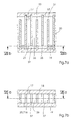
- air restrictors 416, 516, 616, 716 or 816 Embodiments shown in Figures 4 to 8 and with reference thereto are described below.
- a bed 22 from bulk particles, such as. B. granules, fibers, chips or beads, on both sides is held together by a network or grid 23.
- the bulk solids can their stabilization can also be sintered together. Points between the bulk particles the bed 22 on communicating cavities through which the blowing air flows.
- the bed 22 completely fills the cross section of the throttle chamber 21, so that all of the blowing air must flow through the bed 22 and through it Throttling on the bulk solids and turbulence in the cavities throttled becomes.
- the bed 22 is separated by an in the throttle chamber 21 used textile throttle piece 24, such as. B. a fabric or Nonwoven, replaced.
- textile throttle piece 24 such as. B. a fabric or Nonwoven
- this can be made from a single consist of a sufficiently voluminous layer or wound into a multi-layer insert or be spanned in the throttle chamber 21.
- the flowing through the throttle piece 24 Blown air is caused by accumulation of threads or fibers and by swirling in Pores of the throttle piece 24 throttled.
- the air baffles 25 and 26 have a very strong surface roughness, the z. B. is caused by treatment of the air guide walls 25 and 26 by means of sandblasting and that for reducing the flow velocity of the blown air in the air duct 27 contributes by increasing friction.
- a sandwich construction of the air throttle 716 a, b or c is also conceivable, in which the Throttle plate 18 and the throttle plate 19 are designed as lamellae, between which there is an intermediate lamella from which the meandering air duct and the Eddy chambers are spared.
- Such an air throttle is, for. B. by punching the Intermediate lamella, inexpensive to manufacture and can be a lamellar in multiple arrangement Form throttle package.
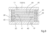
- FIG 8 a section of the air throttle 816 is shown, which from in the throttle chamber There are 21 perforated plates 38 and 39 arranged one above the other. From the perforated plates 38 and 39 each has at least one hole 40 (or 41) which is offset in the plane of the plate at least one hole 41 (or 40) of the adjacent perforated plate is arranged. Thus, the holes 40 and 41 forming a meandering air channel are out of alignment with each other and in overlap with closed plate surfaces of the perforated plates 38 and 39. Spacers 42 and 43 keep the perforated plates 38 and 39 at a distance from one another and determine volumes of vortex chambers lying between perforated plates 38 and 39 44 and 45, through which the blown air flows.
- the throttling effect of the air throttle 816 is based as well the throttling effect of air restrictors 616 and 716 in a reduction in Flow velocity of the blown air through multiple redirection of the air flow in the throttle chamber 21.
- the air nozzles 11, 12 and 46, 47 Guide device 10 between this or its guide surface and a current one Front of the sheet creates a second air cushion B.
- the air nozzle 8, 9 during its transport past the guide device 10 and 11, 12 and 46, 47 sheet 1 blown on both sides moves on a very stable and almost free of lateral acceleration trajectory.
- the sheet 1 can also be very close to the guide device 10 and nevertheless with absolute certainty without striking the guide device 10 the latter are transported past.
- the spring-loaded mounting of the air nozzles 11, 12 shown in FIGS. 2 and 3 is advantageous with regard to the processing of sheets 1 of different substrate thickness.
- FIG. 2 - stands out more from the transport cylinder 5 than a thin sheet (paper sheet) 1 due to its higher inherent rigidity and the greater centrifugal force - cf. Figure 3 - which is less stiff and lighter. So that the throttled air nozzle 12 acts optimally pneumatically on the respective sheet 1, both in the thick and in the thin sheet 1, the air nozzle 12 is automatically extended from the guide device 10 by the spring 52 during processing of the sheet 1 and moved up to the sheet 1 until there is a balance of forces between forces F F and F B.
- F F denotes a dynamic pressure force caused by the expelled blown air 61 of a local air jam between the air nozzle 12 and the sheet 1.
- the dynamic pressure force F B increases until the equilibrium of forces is reached, at which an optimal distance 60 of the air nozzle 12 to the bend 1 corresponds to the close range of the optimal effectiveness of the air nozzle 12.
- Figure 3 - moves the air nozzle 12 further than with the cardboard sheet - cf.
- Figure 2 off, so that the distance between the air nozzle 12 and the sheet 1 in each of the two cases is set to the optimum distance 60, which is independent of the printing material, and thus an automatic printing material adaptation of the air nozzle 12 takes place.
- the spring bearing also causes an automatic adaptation of the air nozzle 12 to the Machine speed by the air nozzle 12 during each transverse movement of the Bow 1 is tracked and by this self-regulation of the air nozzle 12 optimal distance 60 is maintained.
- the transverse movement can be caused by an increase in machine speed, ie an increase in the rotational speed of the transport cylinder 5, as a result of which the centrifugal force acting on the sheet 1 increases and the distance between the rear edge 57 and the transport cylinder 5 increases and decreases to the guide device 10.
- the sheet 1 presses contactlessly, ie without touching the air nozzle 12, via an air cushion located between the sheet 1 and the air nozzle 12 and caused by the local air congestion and against the action of the spring 52, the air nozzle 12 back so far in the direction of the guide device 10 until the optimal distance 60 lost due to the transverse movement is restored very quickly.
- Appropriate adjustment of the spring force F F or a spring characteristic of the spring 52 relative to the dynamic pressure force F B that occurs is a prerequisite for proper functioning.
Landscapes
- Feeding Of Articles By Means Other Than Belts Or Rollers (AREA)
- Supply, Installation And Extraction Of Printed Sheets Or Plates (AREA)
- Delivering By Means Of Belts And Rollers (AREA)
- Treatments Of Macromolecular Shaped Articles (AREA)
- Photographic Processing Devices Using Wet Methods (AREA)
- Iron Core Of Rotating Electric Machines (AREA)
Applications Claiming Priority (2)
| Application Number | Priority Date | Filing Date | Title |
|---|---|---|---|
| DE10042887 | 2000-08-31 | ||
| DE10042887A DE10042887A1 (de) | 2000-08-31 | 2000-08-31 | Maschine zur Verarbeitung von Bogen |
Publications (3)
| Publication Number | Publication Date |
|---|---|
| EP1184174A2 true EP1184174A2 (fr) | 2002-03-06 |
| EP1184174A3 EP1184174A3 (fr) | 2004-03-17 |
| EP1184174B1 EP1184174B1 (fr) | 2006-04-05 |
Family
ID=7654494
Family Applications (1)
| Application Number | Title | Priority Date | Filing Date |
|---|---|---|---|
| EP01116664A Expired - Lifetime EP1184174B1 (fr) | 2000-08-31 | 2001-07-16 | Machine de traitement de feuilles |
Country Status (5)
| Country | Link |
|---|---|
| US (1) | US6662722B2 (fr) |
| EP (1) | EP1184174B1 (fr) |
| JP (1) | JP2002137845A (fr) |
| AT (1) | ATE322383T1 (fr) |
| DE (2) | DE10042887A1 (fr) |
Families Citing this family (7)
| Publication number | Priority date | Publication date | Assignee | Title |
|---|---|---|---|---|
| DE10152593A1 (de) * | 2001-10-24 | 2003-05-08 | Koenig & Bauer Ag | Einrichtung zur Bedruckstoff- und Druckwerkskühlung mittels gekühlter Blasluft an Bogenrotationsdruckmaschinen |
| EP1352738A3 (fr) | 2002-04-08 | 2004-08-04 | Komori Corporation | Appareil de guidage de feuilles |
| DE10310690A1 (de) * | 2002-04-12 | 2003-10-30 | Heidelberger Druckmasch Ag | Bogenführungseinrichtung in einer bogenverarbeitenden Maschine |
| DE10315193A1 (de) * | 2002-04-18 | 2003-10-30 | Heidelberger Druckmasch Ag | Gegendruckzylinder in einer Wendeeinrichtung einer bogenverarbeitenden Maschine |
| JP4503999B2 (ja) * | 2002-12-12 | 2010-07-14 | ハイデルベルガー ドルツクマシーネン アクチエンゲゼルシヤフト | シートガイド装置 |
| DE102004004396A1 (de) * | 2004-01-29 | 2005-08-11 | Heidelberger Druckmaschinen Ag | Vorrichtung zur Erzeugung gedrosselter Blas- oder Saugluft |
| US9776809B1 (en) * | 2016-03-31 | 2017-10-03 | Core Flow Ltd. | Conveying system with vacuum wheel |
Family Cites Families (15)
| Publication number | Priority date | Publication date | Assignee | Title |
|---|---|---|---|---|
| US2753181A (en) * | 1953-05-14 | 1956-07-03 | Powers Chemico Inc | Feed mechanism for web material |
| GB865376A (en) * | 1958-10-14 | 1961-04-19 | Georg Spiess | A separating device for detaching sheets in sheet feeding apparatus |
| US3823743A (en) * | 1970-11-06 | 1974-07-16 | Dunlap Holdings Ltd | Pressure reducing device |
| DE2137115A1 (de) * | 1971-07-24 | 1973-02-01 | Maschf Augsburg Nuernberg Ag | Bogenfoerdereinrichtung |
| US4043360A (en) * | 1975-07-16 | 1977-08-23 | Incontrol Ltd. | Pressure reducing device for fluids |
| US4411292A (en) * | 1981-11-30 | 1983-10-25 | Arminio Schiller | Fluid flow restrictor device |
| DD229360A1 (de) * | 1984-11-27 | 1985-11-06 | Polygraph Leipzig | Blaslufttrommel als uebergabetrommel und auslagetrommel an bogenverarbeitenden maschinen |
| US5156090A (en) * | 1989-06-24 | 1992-10-20 | Heidelberger Druckmaschinen Ag | Device for smoothing a sheet on an impression cylinder of a sheet-fed rotary printing machine |
| DE4223555A1 (de) * | 1991-08-12 | 1993-02-18 | Koenig & Bauer Ag | Trommel zum transportieren von bogen |
| US5327941A (en) * | 1992-06-16 | 1994-07-12 | The United States Of America As Represented By The Secretary Of The Navy | Cascade orificial resistive device |
| DE4436955C2 (de) * | 1994-10-15 | 1999-11-11 | Roland Man Druckmasch | Vorrichtung zum berührungslosen Bogentransport |
| DE19503110B4 (de) * | 1995-02-01 | 2009-01-29 | Heidelberger Druckmaschinen Ag | Bogenleiteinrichtung für Druckmaschinen |
| DE19829095C2 (de) * | 1998-06-30 | 2002-04-25 | Roland Man Druckmasch | Bogenführungseinrichtung in einer Druckmaschine |
| DE19905095C2 (de) * | 1999-02-09 | 2001-02-22 | Roland Man Druckmasch | Bogenführungseinrichtung für eine Druckmaschine |
| US6270074B1 (en) * | 1999-04-14 | 2001-08-07 | Hewlett-Packard Company | Print media vacuum holddown |
-
2000
- 2000-08-31 DE DE10042887A patent/DE10042887A1/de not_active Withdrawn
-
2001
- 2001-07-16 EP EP01116664A patent/EP1184174B1/fr not_active Expired - Lifetime
- 2001-07-16 AT AT01116664T patent/ATE322383T1/de not_active IP Right Cessation
- 2001-07-16 DE DE50109420T patent/DE50109420D1/de not_active Expired - Lifetime
- 2001-08-31 JP JP2001263288A patent/JP2002137845A/ja active Pending
- 2001-08-31 US US09/944,570 patent/US6662722B2/en not_active Expired - Fee Related
Also Published As
| Publication number | Publication date |
|---|---|
| EP1184174A3 (fr) | 2004-03-17 |
| ATE322383T1 (de) | 2006-04-15 |
| EP1184174B1 (fr) | 2006-04-05 |
| DE50109420D1 (de) | 2006-05-18 |
| US6662722B2 (en) | 2003-12-16 |
| DE10042887A1 (de) | 2002-03-14 |
| JP2002137845A (ja) | 2002-05-14 |
| US20020096068A1 (en) | 2002-07-25 |
Similar Documents
| Publication | Publication Date | Title |
|---|---|---|
| EP0792742B2 (fr) | Dispositif de transport de feuilles et procédé de guidage d'un matériau en feuille dans une machine d'impression, en particulier dans une machine rotative offset pour feuilles | |
| DE4447963B4 (de) | Einrichtung zum berührungsfreien Führen bogenförmigen Materials | |
| DE19503110B4 (de) | Bogenleiteinrichtung für Druckmaschinen | |
| EP1184173B1 (fr) | Dispositif de guidage de feuilles | |
| DE4242730A1 (de) | Bogenausleger einer Druckmaschine | |
| EP1476306A1 (fr) | Dispositif de transport de feuilles equipe d'un element guide-feuille | |
| DE10213705C5 (de) | Vorrichtung zum Fördern eines Bogenstroms von einem Bogenstapel zu einer bogenverarbeitenden Maschine | |
| EP1184175B1 (fr) | Cylindre à transport des feuilles | |
| DE19619547A1 (de) | Luftkissendüse und Vorrichtung zur Wärmebehandlung einer kontinuierlich bewegten Warenbahn mit Luftkissendüsen | |
| EP1184174B1 (fr) | Machine de traitement de feuilles | |
| DE19916342A1 (de) | Druckbogenumlenkkeil mit Luftauslässen | |
| DE19523072C2 (de) | Bogenblaseinrichtung für eine Druckmaschine | |
| CH660332A5 (en) | Web-fed offset rotary printing machine | |
| EP1028077A2 (fr) | Dispositif de guidage de feuilles pour une machine à imprimer | |
| DE4014780C2 (de) | Bogenleiteinrichtung | |
| DE4035985B4 (de) | Absaugverfahren und Absaugvorrichtung in einer Papiermaschine | |
| DE102005016783B4 (de) | Bogenbremse | |
| DE69500781T2 (de) | Luftleitflügel für eine pneumatische Wendestange | |
| EP1010525A1 (fr) | Dispositif de guidage de feuilles pour une machine d'impression | |
| DE2024624C3 (de) | Vorrichtung zur Führung einer vorgefalteten Endlosbahn | |
| DE10064588B4 (de) | Vorrichtung zum schwebenden Führen von Bahn- oder Bogenmaterial in einer Verarbeitungsmaschine | |
| DE102014221459A1 (de) | Vorrichtung zum Trocknen von Bogen | |
| DE3130450A1 (de) | Vorrichtung zum trocknen von materialbahnen oder boegen | |
| DE102004060031B4 (de) | Leiteinrichtung zum Leiten von Materialbögen oder Materialbahnen | |
| DE3938863A1 (de) | Vorrichtung zum fuehren frisch bedruckter bogen, vorzugsweise in der auslage von druckmaschinen |
Legal Events
| Date | Code | Title | Description |
|---|---|---|---|
| PUAI | Public reference made under article 153(3) epc to a published international application that has entered the european phase |
Free format text: ORIGINAL CODE: 0009012 |
|
| AK | Designated contracting states |
Kind code of ref document: A2 Designated state(s): AT BE CH CY DE DK ES FI FR GB GR IE IT LI LU MC NL PT SE TR |
|
| AX | Request for extension of the european patent |
Free format text: AL;LT;LV;MK;RO;SI |
|
| PUAL | Search report despatched |
Free format text: ORIGINAL CODE: 0009013 |
|
| AK | Designated contracting states |
Kind code of ref document: A3 Designated state(s): AT BE CH CY DE DK ES FI FR GB GR IE IT LI LU MC NL PT SE TR |
|
| AX | Request for extension of the european patent |
Extension state: AL LT LV MK RO SI |
|
| RIC1 | Information provided on ipc code assigned before grant |
Ipc: 7B 41F 25/00 A |
|
| 17P | Request for examination filed |
Effective date: 20040211 |
|
| 17Q | First examination report despatched |
Effective date: 20041006 |
|
| AKX | Designation fees paid |
Designated state(s): AT BE CH CY DE DK ES FI FR GB GR IE IT LI LU MC NL PT SE TR |
|
| GRAP | Despatch of communication of intention to grant a patent |
Free format text: ORIGINAL CODE: EPIDOSNIGR1 |
|
| GRAS | Grant fee paid |
Free format text: ORIGINAL CODE: EPIDOSNIGR3 |
|
| GRAA | (expected) grant |
Free format text: ORIGINAL CODE: 0009210 |
|
| AK | Designated contracting states |
Kind code of ref document: B1 Designated state(s): AT BE CH CY DE DK ES FI FR GB GR IE IT LI LU MC NL PT SE TR |
|
| PG25 | Lapsed in a contracting state [announced via postgrant information from national office to epo] |
Ref country code: FI Free format text: LAPSE BECAUSE OF FAILURE TO SUBMIT A TRANSLATION OF THE DESCRIPTION OR TO PAY THE FEE WITHIN THE PRESCRIBED TIME-LIMIT Effective date: 20060405 Ref country code: NL Free format text: LAPSE BECAUSE OF FAILURE TO SUBMIT A TRANSLATION OF THE DESCRIPTION OR TO PAY THE FEE WITHIN THE PRESCRIBED TIME-LIMIT Effective date: 20060405 Ref country code: IE Free format text: LAPSE BECAUSE OF FAILURE TO SUBMIT A TRANSLATION OF THE DESCRIPTION OR TO PAY THE FEE WITHIN THE PRESCRIBED TIME-LIMIT Effective date: 20060405 |
|
| REG | Reference to a national code |
Ref country code: GB Ref legal event code: FG4D Free format text: NOT ENGLISH |
|
| REG | Reference to a national code |
Ref country code: CH Ref legal event code: EP |
|
| REG | Reference to a national code |
Ref country code: IE Ref legal event code: FG4D Free format text: LANGUAGE OF EP DOCUMENT: GERMAN |
|
| REF | Corresponds to: |
Ref document number: 50109420 Country of ref document: DE Date of ref document: 20060518 Kind code of ref document: P |
|
| GBT | Gb: translation of ep patent filed (gb section 77(6)(a)/1977) |
Effective date: 20060524 |
|
| PG25 | Lapsed in a contracting state [announced via postgrant information from national office to epo] |
Ref country code: DK Free format text: LAPSE BECAUSE OF FAILURE TO SUBMIT A TRANSLATION OF THE DESCRIPTION OR TO PAY THE FEE WITHIN THE PRESCRIBED TIME-LIMIT Effective date: 20060705 Ref country code: SE Free format text: LAPSE BECAUSE OF FAILURE TO SUBMIT A TRANSLATION OF THE DESCRIPTION OR TO PAY THE FEE WITHIN THE PRESCRIBED TIME-LIMIT Effective date: 20060705 |
|
| PG25 | Lapsed in a contracting state [announced via postgrant information from national office to epo] |
Ref country code: ES Free format text: LAPSE BECAUSE OF FAILURE TO SUBMIT A TRANSLATION OF THE DESCRIPTION OR TO PAY THE FEE WITHIN THE PRESCRIBED TIME-LIMIT Effective date: 20060716 |
|
| PG25 | Lapsed in a contracting state [announced via postgrant information from national office to epo] |
Ref country code: CH Free format text: LAPSE BECAUSE OF NON-PAYMENT OF DUE FEES Effective date: 20060731 Ref country code: BE Free format text: LAPSE BECAUSE OF NON-PAYMENT OF DUE FEES Effective date: 20060731 Ref country code: LI Free format text: LAPSE BECAUSE OF NON-PAYMENT OF DUE FEES Effective date: 20060731 Ref country code: MC Free format text: LAPSE BECAUSE OF NON-PAYMENT OF DUE FEES Effective date: 20060731 |
|
| PG25 | Lapsed in a contracting state [announced via postgrant information from national office to epo] |
Ref country code: PT Free format text: LAPSE BECAUSE OF FAILURE TO SUBMIT A TRANSLATION OF THE DESCRIPTION OR TO PAY THE FEE WITHIN THE PRESCRIBED TIME-LIMIT Effective date: 20060905 |
|
| NLV1 | Nl: lapsed or annulled due to failure to fulfill the requirements of art. 29p and 29m of the patents act | ||
| ET | Fr: translation filed | ||
| REG | Reference to a national code |
Ref country code: IE Ref legal event code: FD4D |
|
| PLBE | No opposition filed within time limit |
Free format text: ORIGINAL CODE: 0009261 |
|
| STAA | Information on the status of an ep patent application or granted ep patent |
Free format text: STATUS: NO OPPOSITION FILED WITHIN TIME LIMIT |
|
| 26N | No opposition filed |
Effective date: 20070108 |
|
| REG | Reference to a national code |
Ref country code: CH Ref legal event code: PL |
|
| PG25 | Lapsed in a contracting state [announced via postgrant information from national office to epo] |
Ref country code: AT Free format text: LAPSE BECAUSE OF NON-PAYMENT OF DUE FEES Effective date: 20060716 |
|
| PGFP | Annual fee paid to national office [announced via postgrant information from national office to epo] |
Ref country code: GB Payment date: 20070626 Year of fee payment: 7 |
|
| BERE | Be: lapsed |
Owner name: HEIDELBERGER DRUCKMASCHINEN A.G. Effective date: 20060731 |
|
| PGFP | Annual fee paid to national office [announced via postgrant information from national office to epo] |
Ref country code: IT Payment date: 20070723 Year of fee payment: 7 |
|
| PG25 | Lapsed in a contracting state [announced via postgrant information from national office to epo] |
Ref country code: GR Free format text: LAPSE BECAUSE OF FAILURE TO SUBMIT A TRANSLATION OF THE DESCRIPTION OR TO PAY THE FEE WITHIN THE PRESCRIBED TIME-LIMIT Effective date: 20060706 |
|
| PGFP | Annual fee paid to national office [announced via postgrant information from national office to epo] |
Ref country code: FR Payment date: 20070718 Year of fee payment: 7 |
|
| PG25 | Lapsed in a contracting state [announced via postgrant information from national office to epo] |
Ref country code: TR Free format text: LAPSE BECAUSE OF FAILURE TO SUBMIT A TRANSLATION OF THE DESCRIPTION OR TO PAY THE FEE WITHIN THE PRESCRIBED TIME-LIMIT Effective date: 20060405 Ref country code: LU Free format text: LAPSE BECAUSE OF NON-PAYMENT OF DUE FEES Effective date: 20060716 |
|
| PG25 | Lapsed in a contracting state [announced via postgrant information from national office to epo] |
Ref country code: CY Free format text: LAPSE BECAUSE OF FAILURE TO SUBMIT A TRANSLATION OF THE DESCRIPTION OR TO PAY THE FEE WITHIN THE PRESCRIBED TIME-LIMIT Effective date: 20060405 |
|
| GBPC | Gb: european patent ceased through non-payment of renewal fee |
Effective date: 20080716 |
|
| REG | Reference to a national code |
Ref country code: FR Ref legal event code: ST Effective date: 20090331 |
|
| PG25 | Lapsed in a contracting state [announced via postgrant information from national office to epo] |
Ref country code: GB Free format text: LAPSE BECAUSE OF NON-PAYMENT OF DUE FEES Effective date: 20080716 |
|
| PG25 | Lapsed in a contracting state [announced via postgrant information from national office to epo] |
Ref country code: IT Free format text: LAPSE BECAUSE OF NON-PAYMENT OF DUE FEES Effective date: 20080716 Ref country code: FR Free format text: LAPSE BECAUSE OF NON-PAYMENT OF DUE FEES Effective date: 20080731 |
|
| PGFP | Annual fee paid to national office [announced via postgrant information from national office to epo] |
Ref country code: DE Payment date: 20120731 Year of fee payment: 12 |
|
| PG25 | Lapsed in a contracting state [announced via postgrant information from national office to epo] |
Ref country code: DE Free format text: LAPSE BECAUSE OF NON-PAYMENT OF DUE FEES Effective date: 20140201 |
|
| REG | Reference to a national code |
Ref country code: DE Ref legal event code: R119 Ref document number: 50109420 Country of ref document: DE Effective date: 20140201 |