EP1184242A2 - Chariot de manutention avec un bloc de batterie - Google Patents
Chariot de manutention avec un bloc de batterie Download PDFInfo
- Publication number
- EP1184242A2 EP1184242A2 EP01121019A EP01121019A EP1184242A2 EP 1184242 A2 EP1184242 A2 EP 1184242A2 EP 01121019 A EP01121019 A EP 01121019A EP 01121019 A EP01121019 A EP 01121019A EP 1184242 A2 EP1184242 A2 EP 1184242A2
- Authority
- EP
- European Patent Office
- Prior art keywords
- industrial truck
- battery block
- end position
- raised
- truck according
- Prior art date
- Legal status (The legal status is an assumption and is not a legal conclusion. Google has not performed a legal analysis and makes no representation as to the accuracy of the status listed.)
- Granted
Links
- 230000005484 gravity Effects 0.000 description 1
- 238000000034 method Methods 0.000 description 1
- 239000000725 suspension Substances 0.000 description 1
Images

Classifications
-
- B—PERFORMING OPERATIONS; TRANSPORTING
- B66—HOISTING; LIFTING; HAULING
- B66F—HOISTING, LIFTING, HAULING OR PUSHING, NOT OTHERWISE PROVIDED FOR, e.g. DEVICES WHICH APPLY A LIFTING OR PUSHING FORCE DIRECTLY TO THE SURFACE OF A LOAD
- B66F9/00—Devices for lifting or lowering bulky or heavy goods for loading or unloading purposes
- B66F9/06—Devices for lifting or lowering bulky or heavy goods for loading or unloading purposes movable, with their loads, on wheels or the like, e.g. fork-lift trucks
- B66F9/075—Constructional features or details
- B66F9/07513—Details concerning the chassis
- B66F9/0754—Battery removal arrangements
-
- B—PERFORMING OPERATIONS; TRANSPORTING
- B60—VEHICLES IN GENERAL
- B60L—PROPULSION OF ELECTRICALLY-PROPELLED VEHICLES; SUPPLYING ELECTRIC POWER FOR AUXILIARY EQUIPMENT OF ELECTRICALLY-PROPELLED VEHICLES; ELECTRODYNAMIC BRAKE SYSTEMS FOR VEHICLES IN GENERAL; MAGNETIC SUSPENSION OR LEVITATION FOR VEHICLES; MONITORING OPERATING VARIABLES OF ELECTRICALLY-PROPELLED VEHICLES; ELECTRIC SAFETY DEVICES FOR ELECTRICALLY-PROPELLED VEHICLES
- B60L50/00—Electric propulsion with power supplied within the vehicle
- B60L50/50—Electric propulsion with power supplied within the vehicle using propulsion power supplied by batteries or fuel cells
- B60L50/60—Electric propulsion with power supplied within the vehicle using propulsion power supplied by batteries or fuel cells using power supplied by batteries
- B60L50/66—Arrangements of batteries
-
- B—PERFORMING OPERATIONS; TRANSPORTING
- B60—VEHICLES IN GENERAL
- B60L—PROPULSION OF ELECTRICALLY-PROPELLED VEHICLES; SUPPLYING ELECTRIC POWER FOR AUXILIARY EQUIPMENT OF ELECTRICALLY-PROPELLED VEHICLES; ELECTRODYNAMIC BRAKE SYSTEMS FOR VEHICLES IN GENERAL; MAGNETIC SUSPENSION OR LEVITATION FOR VEHICLES; MONITORING OPERATING VARIABLES OF ELECTRICALLY-PROPELLED VEHICLES; ELECTRIC SAFETY DEVICES FOR ELECTRICALLY-PROPELLED VEHICLES
- B60L53/00—Methods of charging batteries, specially adapted for electric vehicles; Charging stations or on-board charging equipment therefor; Exchange of energy storage elements in electric vehicles
- B60L53/80—Exchanging energy storage elements, e.g. removable batteries
-
- B—PERFORMING OPERATIONS; TRANSPORTING
- B62—LAND VEHICLES FOR TRAVELLING OTHERWISE THAN ON RAILS
- B62B—HAND-PROPELLED VEHICLES, e.g. HAND CARTS OR PERAMBULATORS; SLEDGES
- B62B3/00—Hand carts having more than one axis carrying transport wheels; Steering devices therefor; Equipment therefor
- B62B3/04—Hand carts having more than one axis carrying transport wheels; Steering devices therefor; Equipment therefor involving means for grappling or securing in place objects to be carried; Loading or unloading equipment
- B62B3/06—Hand carts having more than one axis carrying transport wheels; Steering devices therefor; Equipment therefor involving means for grappling or securing in place objects to be carried; Loading or unloading equipment for simply clearing the load from the ground
- B62B3/0612—Hand carts having more than one axis carrying transport wheels; Steering devices therefor; Equipment therefor involving means for grappling or securing in place objects to be carried; Loading or unloading equipment for simply clearing the load from the ground power operated
-
- B—PERFORMING OPERATIONS; TRANSPORTING
- B60—VEHICLES IN GENERAL
- B60L—PROPULSION OF ELECTRICALLY-PROPELLED VEHICLES; SUPPLYING ELECTRIC POWER FOR AUXILIARY EQUIPMENT OF ELECTRICALLY-PROPELLED VEHICLES; ELECTRODYNAMIC BRAKE SYSTEMS FOR VEHICLES IN GENERAL; MAGNETIC SUSPENSION OR LEVITATION FOR VEHICLES; MONITORING OPERATING VARIABLES OF ELECTRICALLY-PROPELLED VEHICLES; ELECTRIC SAFETY DEVICES FOR ELECTRICALLY-PROPELLED VEHICLES
- B60L2200/00—Type of vehicles
- B60L2200/40—Working vehicles
- B60L2200/42—Fork lift trucks
-
- B—PERFORMING OPERATIONS; TRANSPORTING
- B60—VEHICLES IN GENERAL
- B60Y—INDEXING SCHEME RELATING TO ASPECTS CROSS-CUTTING VEHICLE TECHNOLOGY
- B60Y2200/00—Type of vehicle
- B60Y2200/10—Road Vehicles
- B60Y2200/15—Fork lift trucks, Industrial trucks
-
- B—PERFORMING OPERATIONS; TRANSPORTING
- B62—LAND VEHICLES FOR TRAVELLING OTHERWISE THAN ON RAILS
- B62B—HAND-PROPELLED VEHICLES, e.g. HAND CARTS OR PERAMBULATORS; SLEDGES
- B62B5/00—Accessories or details specially adapted for hand carts
- B62B5/0026—Propulsion aids
- B62B5/0033—Electric motors
- B62B5/0053—Arrangements of batteries
-
- Y—GENERAL TAGGING OF NEW TECHNOLOGICAL DEVELOPMENTS; GENERAL TAGGING OF CROSS-SECTIONAL TECHNOLOGIES SPANNING OVER SEVERAL SECTIONS OF THE IPC; TECHNICAL SUBJECTS COVERED BY FORMER USPC CROSS-REFERENCE ART COLLECTIONS [XRACs] AND DIGESTS
- Y02—TECHNOLOGIES OR APPLICATIONS FOR MITIGATION OR ADAPTATION AGAINST CLIMATE CHANGE
- Y02P—CLIMATE CHANGE MITIGATION TECHNOLOGIES IN THE PRODUCTION OR PROCESSING OF GOODS
- Y02P90/00—Enabling technologies with a potential contribution to greenhouse gas [GHG] emissions mitigation
- Y02P90/60—Electric or hybrid propulsion means for production processes
-
- Y—GENERAL TAGGING OF NEW TECHNOLOGICAL DEVELOPMENTS; GENERAL TAGGING OF CROSS-SECTIONAL TECHNOLOGIES SPANNING OVER SEVERAL SECTIONS OF THE IPC; TECHNICAL SUBJECTS COVERED BY FORMER USPC CROSS-REFERENCE ART COLLECTIONS [XRACs] AND DIGESTS
- Y02—TECHNOLOGIES OR APPLICATIONS FOR MITIGATION OR ADAPTATION AGAINST CLIMATE CHANGE
- Y02T—CLIMATE CHANGE MITIGATION TECHNOLOGIES RELATED TO TRANSPORTATION
- Y02T10/00—Road transport of goods or passengers
- Y02T10/60—Other road transportation technologies with climate change mitigation effect
- Y02T10/70—Energy storage systems for electromobility, e.g. batteries
-
- Y—GENERAL TAGGING OF NEW TECHNOLOGICAL DEVELOPMENTS; GENERAL TAGGING OF CROSS-SECTIONAL TECHNOLOGIES SPANNING OVER SEVERAL SECTIONS OF THE IPC; TECHNICAL SUBJECTS COVERED BY FORMER USPC CROSS-REFERENCE ART COLLECTIONS [XRACs] AND DIGESTS
- Y02—TECHNOLOGIES OR APPLICATIONS FOR MITIGATION OR ADAPTATION AGAINST CLIMATE CHANGE
- Y02T—CLIMATE CHANGE MITIGATION TECHNOLOGIES RELATED TO TRANSPORTATION
- Y02T10/00—Road transport of goods or passengers
- Y02T10/60—Other road transportation technologies with climate change mitigation effect
- Y02T10/7072—Electromobility specific charging systems or methods for batteries, ultracapacitors, supercapacitors or double-layer capacitors
Definitions
- the invention relates to an industrial truck, in particular a driver's lift truck or Operator platform truck, with a battery block and one by means of a lifting device liftable load part, the battery block by at least one roller at least can be raised slightly and the roller can be raised by means of the lifting device.
- Industrial trucks of the type mentioned have a drive part in which the Drive units, a drive wheel and controls of the truck and if necessary, there is a driver's seat and a load section with a Load suspension device that can be raised relative to the drive part.
- the load part usually gets up on a carriageway using load rollers Lifting movement of the load part change its vertical distance to a load frame and thereby support the lifting movement.
- a battery block is arranged in the drive part of the industrial truck Power packs of the industrial truck supplied with electrical energy.
- Power packs of the industrial truck supplied with electrical energy.
- To change the Battery blocks can be moved laterally out of the drive part.
- To make it easier to move the battery pack horizontally it is usual to provide a roller conveyor in the drive part, below the battery block, on which the battery pack can be moved.
- rollers of the roller conveyor vertically movable.
- the battery pack stands firmly during normal operation a footprint.
- the roles are so far for changing the battery block raised to support the weight of the battery pack.
- the lifting of the rollers takes place via a complicated kinematics arrangement Bowden cables and wedges by means of one generated by the lifting device of the load part Force.
- the lifting device usually comprises at least one hydraulic Lift cylinder, however, can also be carried out with electrical or other actuators his.
- the invention is therefore based on the object of an industrial truck of the beginning to provide the type mentioned, in which the battery block by means of at least a roll can be lifted with a simple device.
- a first for the load part upper end position is controllable, in which the battery pack is not raised, and that a second upper end position can be controlled for the load part, in which the battery pack is raised.
- the first upper end position of the load part is during normal operation of the truck to handle loads Controlled regularly. As usual with generic industrial trucks, corresponds this first upper end position of a lifting height of approx. 110 to 150 millimeters. To the Changing the battery block will raise the lifting height to the second upper end position set, which is about 5 to 30 millimeters higher than the first upper end position.
- the arrangement according to the invention can be used in all Generic types of industrial trucks, in particular for driver seat or Operator platform trucks with or without mast, with drawbar-guided high or Pallet trucks or order picking vehicles are used.
- a control element for the control unit is expedient in the area of an operating arrangement Lifting device arranged, the first upper by means of this control End position is controllable.
- the operating arrangement includes those for the operation of the Truck's essential controls, especially for the lifting device, the travel drive and for a steering device.
- the operating arrangement is at the driver's seat or Operator platform trucks often as control panels or as multi-function levers executed, the operating arrangement is on the drawbar-guided lift truck a tiller head.
- an additional control element is provided for the lifting device is, by means of the additional control element, the second upper end position is controllable. By controlling the first and second upper end positions incorrect operation can be avoided with different control elements.
- control element for the first upper End position the second upper end position cannot be controlled.
- the additional control element is also from the operating arrangement is spaced apart.
- a particularly obvious arrangement is when the additional control element is arranged below a hood for the battery block.
- the additional control element can only be operated with the hood open. By opening the hood you can At the same time, the accessibility of the operating arrangement is difficult or difficult Functionality can be restricted.
- a hood Clamping device in active connection, the battery block when the hood is closed braced against a frame of the industrial truck.
- By opening the Hood will automatically release the tension of the battery block, so that this can be lifted by the vertically movable rollers.
- a electrical switching element provided that when reaching the first upper End position changes its switching position. Reaching the first upper end position is thus signaled by the switching element. If the lifting device by means of Control element was actuated to control the first upper end position then the lifting movement automatically by an electrical control off.
- the load part by means of at least of a hydraulic lifting cylinder can be raised when the lifting cylinder is in the second upper end position located a fully retracted or fully extended piston.
- the second upper end position is thus defined by a mechanical end stop of the lifting cylinder.
- the at least one role stored directly or indirectly on the load part.
- the role is thus relative to the load part not movable in height.
- At least one leadership role is provided, which is provided for guiding a side wall of the battery block.
- the Guide rollers also guided in a lateral direction. This is especially true of Significance if the rollers arranged below the battery block on the side of the Center of gravity of the battery block are arranged.
- the raised battery pack is relative to a frame of the truck in the horizontal direction, preferably in the lateral Slidable direction.
- a particularly safe arrangement is present, if at most up to the first upper end position raised load part of the battery block on a frame of the Truck is positively fixed in the horizontal direction. A side This slips the battery pack during normal operation of the Truck prevented safely.
- the Battery block can be lifted from this form-fitting determination and is then slidable on the rollers in the horizontal direction.
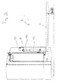
- FIG. 1 shows as a truck according to the invention a driver's seat truck, in which the driver in a driver's seat 1 hidden in this view by a housing part is oriented transversely to the longitudinal direction of the industrial truck.
- Driver's seat is 1 Part of a drive part 2 of the industrial truck, which among other things different Units, a drive wheel 3 and a supporting frame 5 comprises.
- On Battery block 9 stands on the frame 5 of the drive part 2 and has on it Bottom of a paragraph 11, with which he on the frame 5 in the horizontal direction is form-fitting.
- Above the battery pack 10 is on the drive part 2 a hood 12 is arranged, the in the closed position shown Battery block 10 protects against access.
- the hood 12 is by means of a closure 13 locked.
- a tensioning device 14 connected to the hood 12 braces the Battery block 10 against upper guide rollers 15 arranged on the drive part 2, see above that there is no relative movement between the truck during operation Battery block 10 and the drive part 2 takes place.
- the above mentioned Guide rollers 15 and the lower guide rollers 16 guide the battery pack 10 during a battery change process and prevent the Battery blocks 10 on the drive part 2.
- the hood 12 is opened by means of a Gas spring 17 supports, which partially supports the weight of the hood 12 and at the same time dampens its movement. Is located on the underside of the hood 12 an additional control element 18 for a lifting device that before changing the Battery blocks must be operated.
- the load part 4 comprises load rollers standing on the road 6, a fork-forming load arms 7 and a load frame 8. Which to lift The load part 4 required force is by means of a hydraulic lifting cylinder 19th generated with a cylinder tube on a component of the drive part 2 and with a Piston is attached to the load frame 8.
- the vertical position of the load rollers 6 with respect to the load arms 7 becomes automatic when the load part 4 is raised changed by a load roller fork 20 carrying the load rollers 6 in a known manner by means of an angle lever 21 and a schematically indicated rod 22 is pivoted.
- the angle lever 21 is at a first pivot point 23 with the Drive part 2, at a second pivot point 24 with the load part 4 and at a third Pivotal point 25 connected to the rod 22.
- a attached to the drive part 2 as Switching element 26 designed as a microswitch is actuated by the load frame 8, when the load part 4 is raised to a first upper end position.
- Farther are attached to the load part 4 rollers 27, which are raised together with the load part and raise the battery block 10 from a certain lifting height.
- the driver uses a control element, not shown the lifting device is actuated.
- the piston of the lifting cylinder 19 is extended and lifts the load part 4 until the control element is released or that Switching element 26 is actuated after the first upper end position of the lifting device is reached.
- FIG. 2 shows the industrial truck according to FIG. 1 with in the first upper end position located load handler. It can be seen from the lifting cylinder 19 extended piston 19a, with which the load part 4 with the load frame 8 and Load arm 7 was raised.
- the switching element 26 is through the load frame 8 actuated, whereby the lifting movement by an electric, not shown Control of the truck was stopped.
- the rollers 27 are scarce below the battery pack 10, so that its position in the illustrated first upper end position of the load part 4 is not affected.
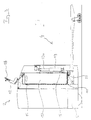
- FIG. 3 shows the truck with in the second upper end position Load part 4.
- the hood 12 of the battery block 10 be opened.
- the additional control element 18 can then be actuated, whereupon the piston 19a of the lifting cylinder 19 is completely extended upwards.
- the load part 4 is moved into the second upper end position shown and the rollers 27 mounted on the load part 4 are raised so far that they are connected to the Contact battery block 10 and lift it up.
- the positive connection of the paragraph 11 of the battery pack 10 with the Frame 5 of the drive part 2 is thereby canceled.
- the battery pack 10 can thereby on the rollers 27 in the transverse direction of the industrial truck, in the present Representation perpendicular to the plane of the drawing.
- the side The battery block 10 is guided by means of the guide rollers 15, 16.
- the in the offset arrangement of the guide rollers 15 and 16 results from the eccentric arrangement of the rollers 27 and prevents tilting of the battery pack 10 counterclockwise.
- rollers 27 of the battery pack 10 So supported with the rollers 27 of the battery pack 10 along the entire length can be several, in the present exemplary embodiment four rollers 27 arranged one behind the other.
- the four rollers 27 are even across the width of the Industrial truck distributed.
- the rollers 27 cover each other so that only one roller 27 is closed is recognizable.
- two lifting cylinders 19, which are located opposite one another on the sides of the industrial truck are located.
Landscapes
- Engineering & Computer Science (AREA)
- Transportation (AREA)
- Mechanical Engineering (AREA)
- Structural Engineering (AREA)
- Power Engineering (AREA)
- Life Sciences & Earth Sciences (AREA)
- Geology (AREA)
- Civil Engineering (AREA)
- Chemical & Material Sciences (AREA)
- Sustainable Development (AREA)
- Sustainable Energy (AREA)
- Combustion & Propulsion (AREA)
- Forklifts And Lifting Vehicles (AREA)
- Arrangement Or Mounting Of Propulsion Units For Vehicles (AREA)
- Battery Mounting, Suspending (AREA)
- Handcart (AREA)
Applications Claiming Priority (2)
| Application Number | Priority Date | Filing Date | Title |
|---|---|---|---|
| DE10043186 | 2000-09-01 | ||
| DE10043186A DE10043186A1 (de) | 2000-09-01 | 2000-09-01 | Flurförderzeug mit einem Batterieblock |
Publications (3)
| Publication Number | Publication Date |
|---|---|
| EP1184242A2 true EP1184242A2 (fr) | 2002-03-06 |
| EP1184242A3 EP1184242A3 (fr) | 2003-11-19 |
| EP1184242B1 EP1184242B1 (fr) | 2006-03-15 |
Family
ID=7654690
Family Applications (1)
| Application Number | Title | Priority Date | Filing Date |
|---|---|---|---|
| EP01121019A Expired - Lifetime EP1184242B1 (fr) | 2000-09-01 | 2001-08-31 | Chariot de manutention avec un bloc de batterie |
Country Status (4)
| Country | Link |
|---|---|
| EP (1) | EP1184242B1 (fr) |
| AT (1) | ATE320361T1 (fr) |
| DE (2) | DE10043186A1 (fr) |
| ES (1) | ES2260136T3 (fr) |
Cited By (2)
| Publication number | Priority date | Publication date | Assignee | Title |
|---|---|---|---|---|
| EP1378407A1 (fr) * | 2002-07-05 | 2004-01-07 | Still Gmbh | Chariot élévateur pour le transport d'un bloc de batterie d'un chariot de manutention |
| EP2607293A1 (fr) * | 2011-12-23 | 2013-06-26 | Jungheinrich Aktiengesellschaft | Chariot de manutention fonctionnant sur batterie |
Families Citing this family (1)
| Publication number | Priority date | Publication date | Assignee | Title |
|---|---|---|---|---|
| DE102007034747B4 (de) * | 2007-07-25 | 2025-02-20 | Linde Material Handling Gmbh | Hubwagen, insbesondere Niederhubwagen |
Family Cites Families (4)
| Publication number | Priority date | Publication date | Assignee | Title |
|---|---|---|---|---|
| GB1123268A (en) * | 1966-10-31 | 1968-08-14 | Ts Kb Proekt Elektropogruzchik | Improvements in lift trucks |
| DE8715557U1 (de) * | 1987-11-24 | 1988-01-21 | Jungheinrich Unternehmensverwaltung Kg, 2000 Hamburg | Führungsvorrichtung für ein Batteriekabel in einem Flurförderzeug |
| GB2331054B (en) * | 1997-11-06 | 2001-08-08 | Lansing Linde Ltd | Industrial truck with a battery block |
| DE29918831U1 (de) * | 1999-10-26 | 2000-02-24 | Linde Ag, 65189 Wiesbaden | Flurförderzeug mit einem Batterieblock |
-
2000
- 2000-09-01 DE DE10043186A patent/DE10043186A1/de not_active Withdrawn
-
2001
- 2001-08-31 EP EP01121019A patent/EP1184242B1/fr not_active Expired - Lifetime
- 2001-08-31 AT AT01121019T patent/ATE320361T1/de not_active IP Right Cessation
- 2001-08-31 DE DE50109201T patent/DE50109201D1/de not_active Expired - Lifetime
- 2001-08-31 ES ES01121019T patent/ES2260136T3/es not_active Expired - Lifetime
Non-Patent Citations (1)
| Title |
|---|
| None |
Cited By (3)
| Publication number | Priority date | Publication date | Assignee | Title |
|---|---|---|---|---|
| EP1378407A1 (fr) * | 2002-07-05 | 2004-01-07 | Still Gmbh | Chariot élévateur pour le transport d'un bloc de batterie d'un chariot de manutention |
| US7163088B2 (en) | 2002-07-05 | 2007-01-16 | Still Gmbh | Lift truck for the transport of a battery block of an industrial truck |
| EP2607293A1 (fr) * | 2011-12-23 | 2013-06-26 | Jungheinrich Aktiengesellschaft | Chariot de manutention fonctionnant sur batterie |
Also Published As
| Publication number | Publication date |
|---|---|
| EP1184242B1 (fr) | 2006-03-15 |
| ES2260136T3 (es) | 2006-11-01 |
| ATE320361T1 (de) | 2006-04-15 |
| EP1184242A3 (fr) | 2003-11-19 |
| DE50109201D1 (de) | 2006-05-11 |
| DE10043186A1 (de) | 2002-03-14 |
Similar Documents
| Publication | Publication Date | Title |
|---|---|---|
| EP0983897B1 (fr) | Dispositif de levage | |
| DE2525124A1 (de) | Hebebuehne | |
| DE3518202A1 (de) | Transportabler wartungslift | |
| DE3880958T2 (de) | Gabeleinheit fuer hubwagen. | |
| DE2460519A1 (de) | Portalhubwagen | |
| DE2654286A1 (de) | Ladevorrichtung fuer lastfahrzeugaufbauten | |
| DE69501578T3 (de) | Motorhubwagen mit teleskopischem Arm | |
| DE3147132C2 (de) | Hubeinrichtung | |
| EP1808402A2 (fr) | Chariot élévateur à petite levée | |
| DE2533398C3 (de) | Vorrichtung zum Anheben von Kraftfahrzeugen | |
| EP0903197A1 (fr) | Dispositif pour changer des cadres de fixations dans une station d'usinage | |
| DE1952159A1 (de) | Hublader | |
| DE102007057678A1 (de) | Kippmechanismus für ein Hubgerüst eines Flurförderzeugs und Transportverfahren für ein Flurförderzeug | |
| EP1661847B1 (fr) | Chariot élévateur avec une surface mobile de support d'un bloc de batterie | |
| EP1184242B1 (fr) | Chariot de manutention avec un bloc de batterie | |
| DE2112545A1 (de) | Verfahrbarer Hubfoerderer | |
| DE3439292A1 (de) | Hydraulisch betaetigte hubvorrichtung, insbesondere hebebuehne fuer kraftfahrzeuge | |
| DE10321773A1 (de) | Gegengewichtstapler | |
| DE19802119A1 (de) | Flurförderzeug mit einer Hubvorrichtung | |
| EP0583546A1 (fr) | Chariot de manutention, en particulier véhicule sans conducteur | |
| DE7825062U1 (de) | Niederhubwagen | |
| DE2743373C3 (de) | Elektrokarren mit Ladeplattform und hinter dem Fahrersitz angeordnetem Hydraulikdrehkran | |
| DE9205223U1 (de) | Gabelhubwagen | |
| DE2357839C3 (de) | Hebebühne | |
| EP2156981B1 (fr) | Elévateur plat |
Legal Events
| Date | Code | Title | Description |
|---|---|---|---|
| PUAI | Public reference made under article 153(3) epc to a published international application that has entered the european phase |
Free format text: ORIGINAL CODE: 0009012 |
|
| AK | Designated contracting states |
Kind code of ref document: A2 Designated state(s): AT BE CH CY DE DK ES FI FR GB GR IE IT LI LU MC NL PT SE TR |
|
| AX | Request for extension of the european patent |
Free format text: AL;LT;LV;MK;RO;SI |
|
| PUAL | Search report despatched |
Free format text: ORIGINAL CODE: 0009013 |
|
| AK | Designated contracting states |
Kind code of ref document: A3 Designated state(s): AT BE CH CY DE DK ES FI FR GB GR IE IT LI LU MC NL PT SE TR |
|
| AX | Request for extension of the european patent |
Extension state: AL LT LV MK RO SI |
|
| RIC1 | Information provided on ipc code assigned before grant |
Ipc: 7B 62B 3/06 B Ipc: 7B 60S 5/06 A Ipc: 7B 60K 1/04 B |
|
| 17P | Request for examination filed |
Effective date: 20040422 |
|
| AKX | Designation fees paid |
Designated state(s): AT BE CH CY DE DK ES FI FR GB GR IE IT LI LU MC NL PT SE TR |
|
| RAP1 | Party data changed (applicant data changed or rights of an application transferred) |
Owner name: OM CARRELLI ELEVATORI S.P.A. |
|
| GRAP | Despatch of communication of intention to grant a patent |
Free format text: ORIGINAL CODE: EPIDOSNIGR1 |
|
| RAP1 | Party data changed (applicant data changed or rights of an application transferred) |
Owner name: OM CARRELLI ELEVATORI S.P.A. |
|
| GRAS | Grant fee paid |
Free format text: ORIGINAL CODE: EPIDOSNIGR3 |
|
| GRAA | (expected) grant |
Free format text: ORIGINAL CODE: 0009210 |
|
| AK | Designated contracting states |
Kind code of ref document: B1 Designated state(s): AT BE CH CY DE DK ES FI FR GB GR IE IT LI LU MC NL PT SE TR |
|
| PG25 | Lapsed in a contracting state [announced via postgrant information from national office to epo] |
Ref country code: IE Free format text: LAPSE BECAUSE OF FAILURE TO SUBMIT A TRANSLATION OF THE DESCRIPTION OR TO PAY THE FEE WITHIN THE PRESCRIBED TIME-LIMIT Effective date: 20060315 Ref country code: FI Free format text: LAPSE BECAUSE OF FAILURE TO SUBMIT A TRANSLATION OF THE DESCRIPTION OR TO PAY THE FEE WITHIN THE PRESCRIBED TIME-LIMIT Effective date: 20060315 Ref country code: NL Free format text: LAPSE BECAUSE OF FAILURE TO SUBMIT A TRANSLATION OF THE DESCRIPTION OR TO PAY THE FEE WITHIN THE PRESCRIBED TIME-LIMIT Effective date: 20060315 |
|
| REG | Reference to a national code |
Ref country code: GB Ref legal event code: FG4D Free format text: NOT ENGLISH Ref country code: CH Ref legal event code: EP |
|
| REG | Reference to a national code |
Ref country code: IE Ref legal event code: FG4D Free format text: LANGUAGE OF EP DOCUMENT: GERMAN |
|
| REF | Corresponds to: |
Ref document number: 50109201 Country of ref document: DE Date of ref document: 20060511 Kind code of ref document: P |
|
| PG25 | Lapsed in a contracting state [announced via postgrant information from national office to epo] |
Ref country code: DK Free format text: LAPSE BECAUSE OF FAILURE TO SUBMIT A TRANSLATION OF THE DESCRIPTION OR TO PAY THE FEE WITHIN THE PRESCRIBED TIME-LIMIT Effective date: 20060615 |
|
| REG | Reference to a national code |
Ref country code: SE Ref legal event code: TRGR |
|
| GBT | Gb: translation of ep patent filed (gb section 77(6)(a)/1977) |
Effective date: 20060627 |
|
| PG25 | Lapsed in a contracting state [announced via postgrant information from national office to epo] |
Ref country code: CH Free format text: LAPSE BECAUSE OF NON-PAYMENT OF DUE FEES Effective date: 20060831 Ref country code: MC Free format text: LAPSE BECAUSE OF NON-PAYMENT OF DUE FEES Effective date: 20060831 Ref country code: LI Free format text: LAPSE BECAUSE OF NON-PAYMENT OF DUE FEES Effective date: 20060831 Ref country code: BE Free format text: LAPSE BECAUSE OF NON-PAYMENT OF DUE FEES Effective date: 20060831 |
|
| NLV1 | Nl: lapsed or annulled due to failure to fulfill the requirements of art. 29p and 29m of the patents act | ||
| REG | Reference to a national code |
Ref country code: IE Ref legal event code: FD4D |
|
| REG | Reference to a national code |
Ref country code: ES Ref legal event code: FG2A Ref document number: 2260136 Country of ref document: ES Kind code of ref document: T3 |
|
| ET | Fr: translation filed | ||
| PLBE | No opposition filed within time limit |
Free format text: ORIGINAL CODE: 0009261 |
|
| STAA | Information on the status of an ep patent application or granted ep patent |
Free format text: STATUS: NO OPPOSITION FILED WITHIN TIME LIMIT |
|
| 26N | No opposition filed |
Effective date: 20061218 |
|
| REG | Reference to a national code |
Ref country code: CH Ref legal event code: PL |
|
| PG25 | Lapsed in a contracting state [announced via postgrant information from national office to epo] |
Ref country code: AT Free format text: LAPSE BECAUSE OF NON-PAYMENT OF DUE FEES Effective date: 20060831 |
|
| BERE | Be: lapsed |
Owner name: OM CARRELLI ELEVATORI S.P.A. Effective date: 20060831 |
|
| PG25 | Lapsed in a contracting state [announced via postgrant information from national office to epo] |
Ref country code: GR Free format text: LAPSE BECAUSE OF FAILURE TO SUBMIT A TRANSLATION OF THE DESCRIPTION OR TO PAY THE FEE WITHIN THE PRESCRIBED TIME-LIMIT Effective date: 20060616 |
|
| PG25 | Lapsed in a contracting state [announced via postgrant information from national office to epo] |
Ref country code: LU Free format text: LAPSE BECAUSE OF NON-PAYMENT OF DUE FEES Effective date: 20060831 Ref country code: TR Free format text: LAPSE BECAUSE OF FAILURE TO SUBMIT A TRANSLATION OF THE DESCRIPTION OR TO PAY THE FEE WITHIN THE PRESCRIBED TIME-LIMIT Effective date: 20060315 |
|
| PG25 | Lapsed in a contracting state [announced via postgrant information from national office to epo] |
Ref country code: CY Free format text: LAPSE BECAUSE OF FAILURE TO SUBMIT A TRANSLATION OF THE DESCRIPTION OR TO PAY THE FEE WITHIN THE PRESCRIBED TIME-LIMIT Effective date: 20060315 |
|
| PG25 | Lapsed in a contracting state [announced via postgrant information from national office to epo] |
Ref country code: PT Free format text: LAPSE BECAUSE OF FAILURE TO SUBMIT A TRANSLATION OF THE DESCRIPTION OR TO PAY THE FEE WITHIN THE PRESCRIBED TIME-LIMIT Effective date: 20060315 |
|
| PGFP | Annual fee paid to national office [announced via postgrant information from national office to epo] |
Ref country code: ES Payment date: 20120824 Year of fee payment: 12 Ref country code: FR Payment date: 20120831 Year of fee payment: 12 Ref country code: IT Payment date: 20120824 Year of fee payment: 12 |
|
| PGFP | Annual fee paid to national office [announced via postgrant information from national office to epo] |
Ref country code: GB Payment date: 20130823 Year of fee payment: 13 |
|
| REG | Reference to a national code |
Ref country code: FR Ref legal event code: ST Effective date: 20140430 |
|
| PG25 | Lapsed in a contracting state [announced via postgrant information from national office to epo] |
Ref country code: IT Free format text: LAPSE BECAUSE OF NON-PAYMENT OF DUE FEES Effective date: 20130831 |
|
| PG25 | Lapsed in a contracting state [announced via postgrant information from national office to epo] |
Ref country code: FR Free format text: LAPSE BECAUSE OF NON-PAYMENT OF DUE FEES Effective date: 20130902 |
|
| REG | Reference to a national code |
Ref country code: ES Ref legal event code: FD2A Effective date: 20140905 |
|
| PGFP | Annual fee paid to national office [announced via postgrant information from national office to epo] |
Ref country code: DE Payment date: 20140821 Year of fee payment: 14 |
|
| PG25 | Lapsed in a contracting state [announced via postgrant information from national office to epo] |
Ref country code: ES Free format text: LAPSE BECAUSE OF NON-PAYMENT OF DUE FEES Effective date: 20130901 |
|
| PGFP | Annual fee paid to national office [announced via postgrant information from national office to epo] |
Ref country code: SE Payment date: 20140821 Year of fee payment: 14 |
|
| GBPC | Gb: european patent ceased through non-payment of renewal fee |
Effective date: 20140831 |
|
| PG25 | Lapsed in a contracting state [announced via postgrant information from national office to epo] |
Ref country code: GB Free format text: LAPSE BECAUSE OF NON-PAYMENT OF DUE FEES Effective date: 20140831 |
|
| REG | Reference to a national code |
Ref country code: DE Ref legal event code: R119 Ref document number: 50109201 Country of ref document: DE |
|
| REG | Reference to a national code |
Ref country code: SE Ref legal event code: EUG |
|
| PG25 | Lapsed in a contracting state [announced via postgrant information from national office to epo] |
Ref country code: SE Free format text: LAPSE BECAUSE OF NON-PAYMENT OF DUE FEES Effective date: 20150901 |
|
| PG25 | Lapsed in a contracting state [announced via postgrant information from national office to epo] |
Ref country code: DE Free format text: LAPSE BECAUSE OF NON-PAYMENT OF DUE FEES Effective date: 20160301 |
|
| REG | Reference to a national code |
Ref country code: DE Ref legal event code: R082 Ref document number: 50109201 Country of ref document: DE Representative=s name: PATENTSHIP PATENTANWALTSGESELLSCHAFT MBH, DE |
|
| REG | Reference to a national code |
Ref country code: DE Ref legal event code: R082 Ref document number: 50109201 Country of ref document: DE Representative=s name: PATENTSHIP PATENTANWALTSGESELLSCHAFT MBH, DE |