EP1184264B1 - Ensemble de structure de caisse à montage rapide - Google Patents
Ensemble de structure de caisse à montage rapide Download PDFInfo
- Publication number
- EP1184264B1 EP1184264B1 EP01402220A EP01402220A EP1184264B1 EP 1184264 B1 EP1184264 B1 EP 1184264B1 EP 01402220 A EP01402220 A EP 01402220A EP 01402220 A EP01402220 A EP 01402220A EP 1184264 B1 EP1184264 B1 EP 1184264B1
- Authority
- EP
- European Patent Office
- Prior art keywords
- assembly
- side members
- sub
- fixing
- vehicle
- Prior art date
- Legal status (The legal status is an assumption and is not a legal conclusion. Google has not performed a legal analysis and makes no representation as to the accuracy of the status listed.)
- Expired - Lifetime
Links
Images


Classifications
-
- B—PERFORMING OPERATIONS; TRANSPORTING
- B62—LAND VEHICLES FOR TRAVELLING OTHERWISE THAN ON RAILS
- B62D—MOTOR VEHICLES; TRAILERS
- B62D21/00—Understructures, i.e. chassis frame on which a vehicle body may be mounted
- B62D21/15—Understructures, i.e. chassis frame on which a vehicle body may be mounted having impact absorbing means, e.g. a frame designed to permanently or temporarily change shape or dimension upon impact with another body
-
- B—PERFORMING OPERATIONS; TRANSPORTING
- B62—LAND VEHICLES FOR TRAVELLING OTHERWISE THAN ON RAILS
- B62D—MOTOR VEHICLES; TRAILERS
- B62D35/00—Vehicle bodies characterised by streamlining
- B62D35/02—Streamlining the undersurfaces
-
- Y—GENERAL TAGGING OF NEW TECHNOLOGICAL DEVELOPMENTS; GENERAL TAGGING OF CROSS-SECTIONAL TECHNOLOGIES SPANNING OVER SEVERAL SECTIONS OF THE IPC; TECHNICAL SUBJECTS COVERED BY FORMER USPC CROSS-REFERENCE ART COLLECTIONS [XRACs] AND DIGESTS
- Y02—TECHNOLOGIES OR APPLICATIONS FOR MITIGATION OR ADAPTATION AGAINST CLIMATE CHANGE
- Y02T—CLIMATE CHANGE MITIGATION TECHNOLOGIES RELATED TO TRANSPORTATION
- Y02T10/00—Road transport of goods or passengers
- Y02T10/80—Technologies aiming to reduce greenhouse gasses emissions common to all road transportation technologies
- Y02T10/82—Elements for improving aerodynamics
-
- Y—GENERAL TAGGING OF NEW TECHNOLOGICAL DEVELOPMENTS; GENERAL TAGGING OF CROSS-SECTIONAL TECHNOLOGIES SPANNING OVER SEVERAL SECTIONS OF THE IPC; TECHNICAL SUBJECTS COVERED BY FORMER USPC CROSS-REFERENCE ART COLLECTIONS [XRACs] AND DIGESTS
- Y02—TECHNOLOGIES OR APPLICATIONS FOR MITIGATION OR ADAPTATION AGAINST CLIMATE CHANGE
- Y02T—CLIMATE CHANGE MITIGATION TECHNOLOGIES RELATED TO TRANSPORTATION
- Y02T10/00—Road transport of goods or passengers
- Y02T10/80—Technologies aiming to reduce greenhouse gasses emissions common to all road transportation technologies
- Y02T10/88—Optimized components or subsystems, e.g. lighting, actively controlled glasses
Definitions
- the invention relates to a body structure assembly of a motor vehicle.
- the invention relates more particularly to a set of motor vehicle body structure, of the type that includes, from front to back, a body structure element that forms including support for mechanical parts of the vehicle, and a rigid cell forming a passenger compartment of the motor vehicle, type in which the body structure element comprises, in a first upper horizontal plane, at least two longitudinal members upper longitudinal lines that extend forward from the cell and, in a second lower horizontal plane, at least one lower element arranged at the front of the cell, and two longitudinal members lower longitudinal lines that extend parallel below upper spars, whose front ends are attached to struts attached to the upper spars, and whose rear ends are threaded onto elements of receiving the lower element for, in the event of a longitudinal impact, transmit to the lower element some of the efforts of deformation.
- Such assemblies mounted on a first vehicle, allow, in case of longitudinal shock with a second oncoming vehicle, to hang organs the second vehicle using the longitudinal members to avoid that, at the moment of impact, the first vehicle does not ride the second vehicle or enter the second vehicle.
- Lower rails have front ends which are rigidly connected to the suspension struts, themselves rigidly connected to the upper spars. Intermediate parts lower spars are for example related to upper spar by means of vertical tie rods, and rear ends of lower spars are threaded with play on elements of reception of the lower element, which is constituted for example by a motor cradle of the vehicle. This configuration allows to unload the upper beams of deformation forces resulting from the shock by directing them towards the engine cradle, thus creating a pathway for this one.
- the editing operation is all the more delicate as a wrong orientation of the tie rods before tightening can lead to cancel the game that must exist between the lower spars and the receiving elements of the engine cradle, thereby creating a track for vibratory lift in the structural element of checkout.
- the invention proposes a body structure assembly for easy assembly, fast, and free of risks of bad positioning.
- the invention proposes a structure assembly of the type described above, characterized in that has a substantially plate-shaped fairing horizontal beam on which the lower spars are attached, to form, before assembly on the vehicle, a subset including means for quick attachment and previous position allow the provisional position by relative to the vehicle before final fixation.
- the invention also proposes a method for mounting a subassembly as described above, characterized in that that, during a first stage of preparation, the spars lower parts are assembled to the fairing, in particular by screwing, then in that the housings comprising the fastening means fast are threaded onto the ends before the longerons lower, and in that a crossbar is attached to the lower longitudinal members to form the subassembly.
- a body structure assembly is for example formed of a rigid cell (not shown) forming the passenger compartment of the vehicle automobile, in front of which extends an element 10 of substantially longitudinal steering box structure "L".
- the body structure element 10 is, for example, welded point on the cell at its rear end 12, which is shown on the right of Figure 1.
- the body structure element 10 comprises, in a first plane "P 1 " upper horizontal, at least two upper longitudinal members 14 which extend forwardly from the cell and whose front ends 16 are for example joined by a transverse beam 18, which can in particular serve as a support for a shield and / or a front panel (not shown) of the vehicle.
- the body structure element 10 comprises a lower element 20, in particular a motor cradle, which extends forwardly from the cell, and two lower longitudinal longerons 22. which extend below and parallel to the upper spars 14.
- the lower spars 22 are fixed at their front ends 24 to suspension struts 26 which are fixed to the upper spars 14.
- the suspension struts 26 are fixed at the front ends 16 of said upper longitudinal members 14 and they are in particular joined by a crossbar 27.
- the suspension legs 26 and the crossbar 27 are in particular made in one piece.
- the intermediate parts 28 of the lower longitudinal members 22 are for example each linked to the upper spar 14 associated 14 through at least one tie rod 30, and the ends rear 32 lower rails 22 are arranged with clearance in view of elements 34 for receiving the engine cradle 20 for, in longitudinal shock, transmit to cradle 20 a part deformation efforts.
- the vehicle In a conventional mount, the vehicle is hooked to a conveyor slowly advancing along the chain of manufacturing.
- the upper rails 14 forming part of the body structure of the vehicle, the operator or a robot mounting mounts first under the front ends 16 of the rails 14 the assembly formed of the suspension struts 26 and of the cross 27 which brings them together.
- the assembly formed of the suspension struts 26 and the crossbar 27 is in particular fixed by screwing the legs of suspension 26 under the front ends 16 of the side members higher 14.
- the operator or robot then threads the rear ends 32 of the lower rails 22 on the receiving elements 34 of the cradle 20, then it fixes the front ends 24 of the side members lower 22 under the legs 26. Then he sets a bar Transverse reinforcement between the lower longitudinal members 22. Finally, the operator fixes tie rods 30 between the longitudinal members upper 14 and the lower longitudinal members 22 using screws 66.
- the mounting of the body structure element 10 is therefore particularly complex and requires, in the current mounting procedures, a number of operations as it is impossible to achieve as part of an assembly in large vehicle series due to the high speed of the conveyor which carries the vehicle's body.
- the invention proposes a body structure assembly of motor vehicle which comprises a fairing 38 in the form of substantially horizontal plate on which are fixed the lower rails 22, so as to form, before their assembly on the vehicle, a subassembly 40 pre-assembled whose means 42 quick fixing allow the implementation temporary position relative to the vehicle before fixing final.
- the fairing 38 presents the form of a plate that extends below the side members 22, transversely and substantially over their entire length.
- the fairing 38 is, in a first step represented by the arrows ET1, fixed to the lower longitudinal members 22, by example by means of screws 64.
- Positioning pins which can come from the molding of the shroud 38, ensure a good geometry of the lower longitudinal members 22 before their fixation with the fairing 38.
- Fasteners 44 shown in FIG. ghost view, are threaded onto the front ends of 24 lower stringers 22. At this stage, the stiffening bar 36 previously described can be screwed between the side members lower 22.
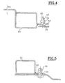
- the two housings 44 for fixing the lower longitudinal members 22 carry the means 42 for quick fixing. These means 42 of quick fastening allow, once mounted in front of lower longitudinal members 22 as shown in FIG. temporary housings 44 under the suspension struts 26.
- the subassembly 40 can be temporarily attached to the vehicle, threading the ends rear 32 lower members on the elements 34 of receiving the engine cradle forming the lower element 20 and fixing the housings 44 under the suspension struts 26.
- the mounting operation can then be completed by screwing the housings 44 for fixing the end of the lower longitudinal members 22 under the suspension struts 26 during a third stage ET3 definitive fixation.
- ties similar to those described with reference to FIG. can be mounted by screwing between the upper rails 14 and lower rails 22.
- tie rods 30 could be assembled to the lower rails 22 during step ET1 preparation by tightening without tightening their lower ends on the lower spars 22.
- this alternative embodiment does not constitute the mode of preferred embodiment of the invention.
- each spar lower 22 includes for example holes 50 regularly spaced along a longitudinally extending wing 52 to the lower spar 22 opposite. Every piercing 50 is intended to receive screws 64 which pass through the fairing 38 for fixing under the lower rails 22. Alternatively, the screws 64 could be advantageously replaced by quick fastening means.
- each housing 44 of fixation is internally complementary to the lower spar 22 and has at least one ear 62 which extends horizontally and transversely towards the housing 44 opposite.
- This ear 62 carries a first means 42 for quick fixing which is arranged opposite a piercing (not shown) of the leg 26 of associated suspension.
- the quick means 42 for fixing the housings 44 are pions known as "pines" which cross the ears 62 of each of the housings 44 and which are shown more particularly in the figure 4.
- the pins 42 are each formed of a vertical rod 54 which is surmounted by a conical portion 60.
- the conical portion 60 is intended to compress by penetrating the associated piercing of the strut 26, then expand to retain the housing 44 under the leg 26.
- the conical portion also fills a centering function in the associated drilling of the leg of suspension 26.
- the vertical rod 54 passes only through the ear 62 and the fairing 38 is arranged with play under the ear 62, but in Alternatively, the shroud 38 could be in contact with the ear 62 and in this case the vertical rod would cross both the ear 62 and the fairing 38.
- the pions known as "fir” could include a stem from which to extend radially a plurality of elastic blades arranged in chevron.
- the subassembly 40 having been pre-assembled during the step ET1, the subassembly 40 can advantageously be put in position during the step ET2 of very easy way under the suspension legs 26, mounting requiring only the screwing during the step ET3 of screw 68 through holes 70 housings 44 for their fixing in holes 48 of the legs 26 of suspension.
- the invention therefore advantageously makes it possible to obtain a 10 body structure element that can be mounted under the vehicle by a single operator as part of an assembly on a large series production line.
Landscapes
- Engineering & Computer Science (AREA)
- Chemical & Material Sciences (AREA)
- Combustion & Propulsion (AREA)
- Transportation (AREA)
- Mechanical Engineering (AREA)
- Body Structure For Vehicles (AREA)
Description
- le sous-ensemble comporte des boítiers pour la fixation des longerons inférieurs sur les jambes de suspension, qui sont enfilés sur les extrémités avant des longerons inférieurs, et qui comportent les moyens de fixation rapide du sous-ensemble sur les jambes de suspension du véhicule,
- l'ensemble comporte une traverse qui réunit les jambes de suspension,
- chaque boítier de fixation comporte au moins une oreille qui s'étend horizontalement et transversalement en direction du boítier opposé, et qui porte un premier moyen de fixation rapide et de mise en position préalable du sous ensemble qui est destiné à coopérer avec un perçage de la jambe'de suspension associée,
- les moyens de fixation rapide et de mise en position préalable du sous ensemble sont des pions de type sapin comportant chacun une tige verticale surmontée d'une partie conique.
- au cours d'une deuxième étape de mise en position, le sous-ensemble est mis en position par rapport au véhicule en enfilant les extrémités arrière des longerons inférieurs sur les éléments de réception de l'élément inférieur et en fixant les moyens de fixation rapide dans les perçages des jambes de suspension,
- dans une troisième étape de fixation définitive, les boítiers d'extrémité des longerons inférieurs sont vissés définitivement sur les jambes de suspension.
- la figure 1 est une vue en perspective éclatée d'un ensemble de structure de caisse selon un état antérieur de la technique,
- la figure 2 est une vue en perspective éclatée d'un ensemble de structure de caisse selon l'invention,
- la figure 3 est une vue de détail en perspective illustrant le sous-ensemble selon l'invention,
- la figure 4 est une vue en coupé transversale par le plan 4-4 de la figure 3 d'un boítier de fixation, et
- la figure 5 est une vue en coupe transversale par le plan 5-5 de la figure 3 d'un longeron inférieur.
Claims (8)
- Ensemble de structure de caisse de véhicule automobile, du type qui comporte, d'avant en arrière, un élément (10) de structure de caisse qui forme notamment support pour des organes mécaniques du véhicule, et une cellule rigide formant habitacle du véhicule automobile, du type dans lequel l'élément (10) de structure de caisse comporte, dans un premier plan (P1) horizontal supérieur, au moins deux longerons (14) longitudinaux supérieurs qui s'étendent vers l'avant à partir de la cellule et, dans un second plan horizontal (P2) inférieur, au moins un élément inférieur (20) agencé à l'avant de la cellule, et deux longerons longitudinaux inférieurs (22) qui s'étendent parallèlement en dessous des longerons supérieurs (14), dont des extrémités avant (24) sont fixées à des jambes de suspension (26) fixées aux longerons supérieurs (14), et dont des extrémités arrière (32) sont enfilées sur des éléments de réception (34) de l'élément inférieur (20) pour, en cas de choc longitudinal, transmettre à l'élément inférieur (20) une partie des efforts de déformation,
caractérisé en ce qu'il comporte un carénage (38) en forme de plaque sensiblement horizontale sur lequel sont fixés les longerons inférieurs (22), de manière à former, avant leur assemblage sur le véhicule, un sous-ensemble (40) dont des moyens (42) de fixation rapide et de mise en position préalable permettent la mise en position provisoire par rapport au véhicule avant la fixation définitive. - Ensemble selon la revendication 1, caractérisé en ce que le sous-ensemble (40) comporte des boítiers (44) pour la fixation des longerons inférieurs (22) sur les jambes de suspension (26), qui sont enfilés sur les extrémités avant (24) des longerons inférieurs (22), et qui comportent les moyens (42) de fixation rapide du sous-ensemble (40) sur les jambes (26) de suspension du véhicule.
- Ensemble selon la revendication précédente, caractérisé en ce qu'il comporte une traverse (27) qui réunit les jambes (26) de suspension.
- Ensemble selon la revendication précédente, caractérisé en ce que chaque boítier (44) de fixation comporte au moins une oreille (62) qui s'étend horizontalement et transversalement en direction du boítier (44) opposé, et qui porte un premier moyen (42) de fixation rapide et de mise en position préalable du sous ensemble (40) qui est destiné à coopérer avec un perçage de la jambe de suspension (26) associée.
- Ensemble selon la revendication 4, caractérisé en ce que les moyens (42) de fixation rapide sont des pions de type sapin comportant chacun une tige verticale (54) surmontée d'une partie conique (56).
- Procédé pour le montage d'un sous ensemble (40) selon les revendications 1 à 5, caractérisé en ce que, au cours d'une première étape de préparation (ET1), les longerons inférieurs (22) sont assemblés au carénage (38), notamment par vissage, puis en ce que les boítiers (44) comportant les moyens (42) de fixation rapide sont enfilés sur les extrémités avant (24) des longerons inférieurs (22), et en ce qu'une barre transversale (36) est fixée aux longerons inférieurs (24) pour former le sous-ensemble (40).
- Procédé de montage d'un sous-ensemble (40) selon la revendication 6, caractérisé en ce que, au cours d'une deuxième étape (ET2) de mise en position, le sous-ensemble (40) est mis en position par rapport au véhicule en enfilant les extrémités arrière (32) des longerons inférieurs (22) sur les éléments (34) de réception de l'élément inférieur (20) et en fixant les moyens (42) de fixation rapide dans les perçages des jambes de suspension (26).
- Procédé de montage d'un sous-ensemble (40) selon la revendication 7, caractérisé en ce que, dans une troisième étape (ET3) de fixation définitive, les boítiers (44) d'extrémité des longerons inférieurs (22) sont vissés définitivement sur les jambes de suspension (26).
Applications Claiming Priority (2)
| Application Number | Priority Date | Filing Date | Title |
|---|---|---|---|
| FR0011047 | 2000-08-29 | ||
| FR0011047A FR2813272B1 (fr) | 2000-08-29 | 2000-08-29 | Ensemble de structure de caisse a montage rapide |
Publications (2)
| Publication Number | Publication Date |
|---|---|
| EP1184264A1 EP1184264A1 (fr) | 2002-03-06 |
| EP1184264B1 true EP1184264B1 (fr) | 2005-03-16 |
Family
ID=8853802
Family Applications (1)
| Application Number | Title | Priority Date | Filing Date |
|---|---|---|---|
| EP01402220A Expired - Lifetime EP1184264B1 (fr) | 2000-08-29 | 2001-08-24 | Ensemble de structure de caisse à montage rapide |
Country Status (4)
| Country | Link |
|---|---|
| EP (1) | EP1184264B1 (fr) |
| DE (1) | DE60109374T2 (fr) |
| ES (1) | ES2236161T3 (fr) |
| FR (1) | FR2813272B1 (fr) |
Families Citing this family (5)
| Publication number | Priority date | Publication date | Assignee | Title |
|---|---|---|---|---|
| JP4250414B2 (ja) | 2002-12-24 | 2009-04-08 | アイシン精機株式会社 | レール位置検出装置 |
| FR2915167A1 (fr) * | 2007-04-20 | 2008-10-24 | Renault Sas | Dispositif d'absorption d'efforts en voie basse de vehicule automobile |
| JP6481704B2 (ja) * | 2017-03-27 | 2019-03-13 | マツダ株式会社 | フロントサブフレーム構造 |
| CN114013514B (zh) * | 2021-10-26 | 2022-08-23 | 东风越野车有限公司 | 一种越野车车身前机舱纵梁结构 |
| CN116374008B (zh) * | 2023-05-05 | 2026-04-03 | 北京汽车集团越野车有限公司 | 悬置安装组件、发动机舱和车辆 |
Family Cites Families (6)
| Publication number | Priority date | Publication date | Assignee | Title |
|---|---|---|---|---|
| DE3322334A1 (de) * | 1983-06-22 | 1985-01-03 | Volkswagenwerk Ag, 3180 Wolfsburg | Kraftfahrzeugendbereich |
| FR2621550B1 (fr) * | 1987-10-07 | 1990-02-23 | Peugeot | Structure de vehicule automobile a caisse monocoque et son procede de montage |
| CH688487A5 (de) * | 1993-12-14 | 1997-10-15 | Alusuisse Lonza Services Ag | Steckverbindung. |
| US6099039A (en) * | 1997-03-10 | 2000-08-08 | Hine; Alan | Frame structure for sport utility vehicle or light truck |
| DE19812701B4 (de) * | 1998-03-23 | 2008-08-28 | Volkswagen Ag | Karosseriestruktur für den Frontbereich eines Kraftfahrzeuges |
| DE19959607A1 (de) * | 1999-12-10 | 2001-06-13 | Volkswagen Ag | Fahrzeugkarosserie mit einer bodenseitigen Verstrebungsanordnung |
-
2000
- 2000-08-29 FR FR0011047A patent/FR2813272B1/fr not_active Expired - Lifetime
-
2001
- 2001-08-24 ES ES01402220T patent/ES2236161T3/es not_active Expired - Lifetime
- 2001-08-24 EP EP01402220A patent/EP1184264B1/fr not_active Expired - Lifetime
- 2001-08-24 DE DE60109374T patent/DE60109374T2/de not_active Expired - Lifetime
Also Published As
| Publication number | Publication date |
|---|---|
| DE60109374T2 (de) | 2006-03-16 |
| DE60109374D1 (de) | 2005-04-21 |
| ES2236161T3 (es) | 2005-07-16 |
| FR2813272A1 (fr) | 2002-03-01 |
| FR2813272B1 (fr) | 2002-11-01 |
| EP1184264A1 (fr) | 2002-03-06 |
Similar Documents
| Publication | Publication Date | Title |
|---|---|---|
| CA2736911C (fr) | Partie arriere d'aeronef comprenant deux demi-structures de support de moteurs rapportees l'une sur l'autre au sein d'un espace interieur d'aeronef | |
| CA2736777C (fr) | Partie arriere d'aeronef comprenant une structure de support de moteurs traversant le fuselage et reliee a celui-ci par au moins une bielle | |
| FR3082823A1 (fr) | Module pour aeronef presentant une conception facilitant son assemblage dans un espace interieur defini par le fuselage de l'aeronef | |
| EP1184264B1 (fr) | Ensemble de structure de caisse à montage rapide | |
| EP2334554B1 (fr) | Partie arriere d'aeronef comprenant une structure de support de moteurs reliee au fuselage par au moins un element de blocage sollicite en compression | |
| EP4124478A1 (fr) | Bras ou triangle de suspension et procédé de fabrication d'un tel bras ou triangle de suspension | |
| FR2977222A3 (fr) | Renfort d'ensemble de jupe arriere | |
| EP2352674B1 (fr) | Ensemble moteur pour aeronef comprenant une structure rigide modulaire de mat d'accrochage | |
| EP2132055B1 (fr) | Procédé de montage d'un élément de soubassement transversal et d'une face avant technique sur un véhicule automobile | |
| EP1184263A1 (fr) | Ensemble de structure de caisse comportant des moyens de fixation d'un organe | |
| FR2961140A1 (fr) | Benne du type positionnable sur le chassis de tout vehicule utilitaire | |
| WO2009130431A2 (fr) | Structure de caisse d'un vehicule | |
| EP1693283A1 (fr) | Structure avant de véhicule automobile | |
| EP1231131B1 (fr) | Face avant technique de véhicule automobile munie d'un moyen de liaison à une poutre basse et ensemble constitué par une face avant technique et sa poutre basse | |
| FR2887217A1 (fr) | Structure de support d'un pavillon de vehicule automobile | |
| FR2560853A1 (fr) | Chassis d'engin volant du type leger | |
| EP2976187B1 (fr) | Dispositif de mise en reference du plateau mobile par rapport au plateau fixe d'une main de prehension d'un robot | |
| EP3974294B1 (fr) | Procédé d'assemblage d'un véhicule automobile à motorisation électrique ou hybride | |
| EP1847445B1 (fr) | Structure avant de véhicule automobile et un procédé correspondant | |
| FR3014809A1 (fr) | Structure de chassis arriere de vehicule a longeronnets relies l'un a l'autre par un support liberable de l'un des longeronnets en cas de choc arriere | |
| WO2025032290A1 (fr) | Plancher de vehicule equipe d'un dispositif anti deversement des traverses d'assise | |
| FR3156718A1 (fr) | Caisse de véhicule comportant un dispositif d’indexage de siège fixé à une traverse, et véhicule comportant une telle caisse. | |
| EP4613516A1 (fr) | Barre de liaison pour le maintien d'un module de chauffage et/ou de climatisation dans un compartiment de véhicule automobile | |
| FR3143532A1 (fr) | Ensemble de véhicule automobile et véhicule automobile comportant un tel ensemble | |
| WO2024134046A1 (fr) | Etrier de renfort d'un tunnel de véhicule |
Legal Events
| Date | Code | Title | Description |
|---|---|---|---|
| PUAI | Public reference made under article 153(3) epc to a published international application that has entered the european phase |
Free format text: ORIGINAL CODE: 0009012 |
|
| AK | Designated contracting states |
Kind code of ref document: A1 Designated state(s): AT BE CH CY DE DK ES FI FR GB GR IE IT LI LU MC NL PT SE TR |
|
| AX | Request for extension of the european patent |
Free format text: AL;LT;LV;MK;RO;SI |
|
| RAP1 | Party data changed (applicant data changed or rights of an application transferred) |
Owner name: RENAULT S.A.S. |
|
| 17P | Request for examination filed |
Effective date: 20020805 |
|
| AKX | Designation fees paid |
Free format text: BE DE ES GB IT |
|
| GRAP | Despatch of communication of intention to grant a patent |
Free format text: ORIGINAL CODE: EPIDOSNIGR1 |
|
| GRAS | Grant fee paid |
Free format text: ORIGINAL CODE: EPIDOSNIGR3 |
|
| GRAA | (expected) grant |
Free format text: ORIGINAL CODE: 0009210 |
|
| AK | Designated contracting states |
Kind code of ref document: B1 Designated state(s): BE DE ES GB IT |
|
| REG | Reference to a national code |
Ref country code: GB Ref legal event code: FG4D Free format text: NOT ENGLISH |
|
| REG | Reference to a national code |
Ref country code: IE Ref legal event code: FG4D Free format text: FRENCH |
|
| REF | Corresponds to: |
Ref document number: 60109374 Country of ref document: DE Date of ref document: 20050421 Kind code of ref document: P |
|
| GBT | Gb: translation of ep patent filed (gb section 77(6)(a)/1977) |
Effective date: 20050523 |
|
| REG | Reference to a national code |
Ref country code: ES Ref legal event code: FG2A Ref document number: 2236161 Country of ref document: ES Kind code of ref document: T3 |
|
| PLBE | No opposition filed within time limit |
Free format text: ORIGINAL CODE: 0009261 |
|
| STAA | Information on the status of an ep patent application or granted ep patent |
Free format text: STATUS: NO OPPOSITION FILED WITHIN TIME LIMIT |
|
| 26N | No opposition filed |
Effective date: 20051219 |
|
| PGFP | Annual fee paid to national office [announced via postgrant information from national office to epo] |
Ref country code: DE Payment date: 20130821 Year of fee payment: 13 Ref country code: ES Payment date: 20130829 Year of fee payment: 13 |
|
| PGFP | Annual fee paid to national office [announced via postgrant information from national office to epo] |
Ref country code: GB Payment date: 20130821 Year of fee payment: 13 |
|
| PGFP | Annual fee paid to national office [announced via postgrant information from national office to epo] |
Ref country code: IT Payment date: 20130826 Year of fee payment: 13 |
|
| PGFP | Annual fee paid to national office [announced via postgrant information from national office to epo] |
Ref country code: BE Payment date: 20130823 Year of fee payment: 13 |
|
| REG | Reference to a national code |
Ref country code: DE Ref legal event code: R119 Ref document number: 60109374 Country of ref document: DE |
|
| GBPC | Gb: european patent ceased through non-payment of renewal fee |
Effective date: 20140824 |
|
| PG25 | Lapsed in a contracting state [announced via postgrant information from national office to epo] |
Ref country code: IT Free format text: LAPSE BECAUSE OF NON-PAYMENT OF DUE FEES Effective date: 20140824 Ref country code: BE Free format text: LAPSE BECAUSE OF NON-PAYMENT OF DUE FEES Effective date: 20140831 |
|
| REG | Reference to a national code |
Ref country code: DE Ref legal event code: R119 Ref document number: 60109374 Country of ref document: DE Effective date: 20150303 |
|
| PG25 | Lapsed in a contracting state [announced via postgrant information from national office to epo] |
Ref country code: GB Free format text: LAPSE BECAUSE OF NON-PAYMENT OF DUE FEES Effective date: 20140824 Ref country code: DE Free format text: LAPSE BECAUSE OF NON-PAYMENT OF DUE FEES Effective date: 20150303 |
|
| REG | Reference to a national code |
Ref country code: ES Ref legal event code: FD2A Effective date: 20150925 |
|
| PG25 | Lapsed in a contracting state [announced via postgrant information from national office to epo] |
Ref country code: ES Free format text: LAPSE BECAUSE OF NON-PAYMENT OF DUE FEES Effective date: 20140825 |