EP1184555A2 - Abgasreinigungsvorrichtung für eine Brennkraftmaschine - Google Patents
Abgasreinigungsvorrichtung für eine Brennkraftmaschine Download PDFInfo
- Publication number
- EP1184555A2 EP1184555A2 EP01119941A EP01119941A EP1184555A2 EP 1184555 A2 EP1184555 A2 EP 1184555A2 EP 01119941 A EP01119941 A EP 01119941A EP 01119941 A EP01119941 A EP 01119941A EP 1184555 A2 EP1184555 A2 EP 1184555A2
- Authority
- EP
- European Patent Office
- Prior art keywords
- exhaust gas
- catalyst
- amount
- fuel ratio
- air
- Prior art date
- Legal status (The legal status is an assumption and is not a legal conclusion. Google has not performed a legal analysis and makes no representation as to the accuracy of the status listed.)
- Granted
Links
Images




Classifications
-
- B—PERFORMING OPERATIONS; TRANSPORTING
- B01—PHYSICAL OR CHEMICAL PROCESSES OR APPARATUS IN GENERAL
- B01D—SEPARATION
- B01D53/00—Separation of gases or vapours; Recovering vapours of volatile solvents from gases; Chemical or biological purification of waste gases, e.g. engine exhaust gases, smoke, fumes, flue gases, aerosols
- B01D53/34—Chemical or biological purification of waste gases
- B01D53/92—Chemical or biological purification of waste gases of engine exhaust gases
- B01D53/94—Chemical or biological purification of waste gases of engine exhaust gases by catalytic processes
- B01D53/9481—Catalyst preceded by an adsorption device without catalytic function for temporary storage of contaminants, e.g. during cold start
-
- B—PERFORMING OPERATIONS; TRANSPORTING
- B01—PHYSICAL OR CHEMICAL PROCESSES OR APPARATUS IN GENERAL
- B01D—SEPARATION
- B01D53/00—Separation of gases or vapours; Recovering vapours of volatile solvents from gases; Chemical or biological purification of waste gases, e.g. engine exhaust gases, smoke, fumes, flue gases, aerosols
- B01D53/34—Chemical or biological purification of waste gases
- B01D53/92—Chemical or biological purification of waste gases of engine exhaust gases
- B01D53/94—Chemical or biological purification of waste gases of engine exhaust gases by catalytic processes
- B01D53/9459—Removing one or more of nitrogen oxides, carbon monoxide, or hydrocarbons by multiple successive catalytic functions; systems with more than one different function, e.g. zone coated catalysts
- B01D53/9477—Removing one or more of nitrogen oxides, carbon monoxide, or hydrocarbons by multiple successive catalytic functions; systems with more than one different function, e.g. zone coated catalysts with catalysts positioned on separate bricks, e.g. exhaust systems
-
- B—PERFORMING OPERATIONS; TRANSPORTING
- B01—PHYSICAL OR CHEMICAL PROCESSES OR APPARATUS IN GENERAL
- B01D—SEPARATION
- B01D53/00—Separation of gases or vapours; Recovering vapours of volatile solvents from gases; Chemical or biological purification of waste gases, e.g. engine exhaust gases, smoke, fumes, flue gases, aerosols
- B01D53/34—Chemical or biological purification of waste gases
- B01D53/92—Chemical or biological purification of waste gases of engine exhaust gases
- B01D53/94—Chemical or biological purification of waste gases of engine exhaust gases by catalytic processes
- B01D53/9495—Controlling the catalytic process
-
- F—MECHANICAL ENGINEERING; LIGHTING; HEATING; WEAPONS; BLASTING
- F01—MACHINES OR ENGINES IN GENERAL; ENGINE PLANTS IN GENERAL; STEAM ENGINES
- F01N—GAS-FLOW SILENCERS OR EXHAUST APPARATUS FOR MACHINES OR ENGINES IN GENERAL; GAS-FLOW SILENCERS OR EXHAUST APPARATUS FOR INTERNAL-COMBUSTION ENGINES
- F01N13/00—Exhaust or silencing apparatus characterised by constructional features
- F01N13/009—Exhaust or silencing apparatus characterised by constructional features having two or more separate purifying devices arranged in series
-
- F—MECHANICAL ENGINEERING; LIGHTING; HEATING; WEAPONS; BLASTING
- F01—MACHINES OR ENGINES IN GENERAL; ENGINE PLANTS IN GENERAL; STEAM ENGINES
- F01N—GAS-FLOW SILENCERS OR EXHAUST APPARATUS FOR MACHINES OR ENGINES IN GENERAL; GAS-FLOW SILENCERS OR EXHAUST APPARATUS FOR INTERNAL-COMBUSTION ENGINES
- F01N13/00—Exhaust or silencing apparatus characterised by constructional features
- F01N13/009—Exhaust or silencing apparatus characterised by constructional features having two or more separate purifying devices arranged in series
- F01N13/0093—Exhaust or silencing apparatus characterised by constructional features having two or more separate purifying devices arranged in series the purifying devices are of the same type
-
- F—MECHANICAL ENGINEERING; LIGHTING; HEATING; WEAPONS; BLASTING
- F01—MACHINES OR ENGINES IN GENERAL; ENGINE PLANTS IN GENERAL; STEAM ENGINES
- F01N—GAS-FLOW SILENCERS OR EXHAUST APPARATUS FOR MACHINES OR ENGINES IN GENERAL; GAS-FLOW SILENCERS OR EXHAUST APPARATUS FOR INTERNAL-COMBUSTION ENGINES
- F01N3/00—Exhaust or silencing apparatus having means for purifying, rendering innocuous, or otherwise treating exhaust
- F01N3/08—Exhaust or silencing apparatus having means for purifying, rendering innocuous, or otherwise treating exhaust for rendering innocuous
- F01N3/0807—Exhaust or silencing apparatus having means for purifying, rendering innocuous, or otherwise treating exhaust for rendering innocuous by using absorbents or adsorbents
- F01N3/0828—Exhaust or silencing apparatus having means for purifying, rendering innocuous, or otherwise treating exhaust for rendering innocuous by using absorbents or adsorbents characterised by the absorbed or adsorbed substances
- F01N3/0842—Nitrogen oxides
-
- F—MECHANICAL ENGINEERING; LIGHTING; HEATING; WEAPONS; BLASTING
- F01—MACHINES OR ENGINES IN GENERAL; ENGINE PLANTS IN GENERAL; STEAM ENGINES
- F01N—GAS-FLOW SILENCERS OR EXHAUST APPARATUS FOR MACHINES OR ENGINES IN GENERAL; GAS-FLOW SILENCERS OR EXHAUST APPARATUS FOR INTERNAL-COMBUSTION ENGINES
- F01N3/00—Exhaust or silencing apparatus having means for purifying, rendering innocuous, or otherwise treating exhaust
- F01N3/08—Exhaust or silencing apparatus having means for purifying, rendering innocuous, or otherwise treating exhaust for rendering innocuous
- F01N3/10—Exhaust or silencing apparatus having means for purifying, rendering innocuous, or otherwise treating exhaust for rendering innocuous by thermal or catalytic conversion of noxious components of exhaust
- F01N3/101—Three-way catalysts
-
- F—MECHANICAL ENGINEERING; LIGHTING; HEATING; WEAPONS; BLASTING
- F02—COMBUSTION ENGINES; HOT-GAS OR COMBUSTION-PRODUCT ENGINE PLANTS
- F02D—CONTROLLING COMBUSTION ENGINES
- F02D41/00—Electrical control of supply of combustible mixture or its constituents
- F02D41/02—Circuit arrangements for generating control signals
- F02D41/021—Introducing corrections for particular conditions exterior to the engine
- F02D41/0235—Introducing corrections for particular conditions exterior to the engine in relation with the state of the exhaust gas treating apparatus
- F02D41/027—Introducing corrections for particular conditions exterior to the engine in relation with the state of the exhaust gas treating apparatus to purge or regenerate the exhaust gas treating apparatus
- F02D41/0275—Introducing corrections for particular conditions exterior to the engine in relation with the state of the exhaust gas treating apparatus to purge or regenerate the exhaust gas treating apparatus the exhaust gas treating apparatus being a NOx trap or adsorbent
-
- F—MECHANICAL ENGINEERING; LIGHTING; HEATING; WEAPONS; BLASTING
- F02—COMBUSTION ENGINES; HOT-GAS OR COMBUSTION-PRODUCT ENGINE PLANTS
- F02D—CONTROLLING COMBUSTION ENGINES
- F02D41/00—Electrical control of supply of combustible mixture or its constituents
- F02D41/02—Circuit arrangements for generating control signals
- F02D41/021—Introducing corrections for particular conditions exterior to the engine
- F02D41/0235—Introducing corrections for particular conditions exterior to the engine in relation with the state of the exhaust gas treating apparatus
- F02D41/0295—Control according to the amount of oxygen that is stored on the exhaust gas treating apparatus
-
- B—PERFORMING OPERATIONS; TRANSPORTING
- B01—PHYSICAL OR CHEMICAL PROCESSES OR APPARATUS IN GENERAL
- B01D—SEPARATION
- B01D2255/00—Catalysts
- B01D2255/90—Physical characteristics of catalysts
- B01D2255/91—NOx-storage component incorporated in the catalyst
-
- B—PERFORMING OPERATIONS; TRANSPORTING
- B01—PHYSICAL OR CHEMICAL PROCESSES OR APPARATUS IN GENERAL
- B01D—SEPARATION
- B01D53/00—Separation of gases or vapours; Recovering vapours of volatile solvents from gases; Chemical or biological purification of waste gases, e.g. engine exhaust gases, smoke, fumes, flue gases, aerosols
- B01D53/34—Chemical or biological purification of waste gases
- B01D53/92—Chemical or biological purification of waste gases of engine exhaust gases
- B01D53/94—Chemical or biological purification of waste gases of engine exhaust gases by catalytic processes
- B01D53/9404—Removing only nitrogen compounds
- B01D53/9409—Nitrogen oxides
- B01D53/9413—Processes characterised by a specific catalyst
- B01D53/9422—Processes characterised by a specific catalyst for removing nitrogen oxides by NOx storage or reduction by cyclic switching between lean and rich exhaust gases (LNT, NSC, NSR)
-
- B—PERFORMING OPERATIONS; TRANSPORTING
- B01—PHYSICAL OR CHEMICAL PROCESSES OR APPARATUS IN GENERAL
- B01D—SEPARATION
- B01D53/00—Separation of gases or vapours; Recovering vapours of volatile solvents from gases; Chemical or biological purification of waste gases, e.g. engine exhaust gases, smoke, fumes, flue gases, aerosols
- B01D53/34—Chemical or biological purification of waste gases
- B01D53/92—Chemical or biological purification of waste gases of engine exhaust gases
- B01D53/94—Chemical or biological purification of waste gases of engine exhaust gases by catalytic processes
- B01D53/9445—Simultaneously removing carbon monoxide, hydrocarbons or nitrogen oxides making use of three-way catalysts [TWC] or four-way-catalysts [FWC]
- B01D53/945—Simultaneously removing carbon monoxide, hydrocarbons or nitrogen oxides making use of three-way catalysts [TWC] or four-way-catalysts [FWC] characterised by a specific catalyst
-
- F—MECHANICAL ENGINEERING; LIGHTING; HEATING; WEAPONS; BLASTING
- F01—MACHINES OR ENGINES IN GENERAL; ENGINE PLANTS IN GENERAL; STEAM ENGINES
- F01N—GAS-FLOW SILENCERS OR EXHAUST APPARATUS FOR MACHINES OR ENGINES IN GENERAL; GAS-FLOW SILENCERS OR EXHAUST APPARATUS FOR INTERNAL-COMBUSTION ENGINES
- F01N2570/00—Exhaust treating apparatus eliminating, absorbing or adsorbing specific elements or compounds
- F01N2570/16—Oxygen
-
- F—MECHANICAL ENGINEERING; LIGHTING; HEATING; WEAPONS; BLASTING
- F02—COMBUSTION ENGINES; HOT-GAS OR COMBUSTION-PRODUCT ENGINE PLANTS
- F02D—CONTROLLING COMBUSTION ENGINES
- F02D2200/00—Input parameters for engine control
- F02D2200/02—Input parameters for engine control the parameters being related to the engine
- F02D2200/08—Exhaust gas treatment apparatus parameters
- F02D2200/0814—Oxygen storage amount
-
- Y—GENERAL TAGGING OF NEW TECHNOLOGICAL DEVELOPMENTS; GENERAL TAGGING OF CROSS-SECTIONAL TECHNOLOGIES SPANNING OVER SEVERAL SECTIONS OF THE IPC; TECHNICAL SUBJECTS COVERED BY FORMER USPC CROSS-REFERENCE ART COLLECTIONS [XRACs] AND DIGESTS
- Y02—TECHNOLOGIES OR APPLICATIONS FOR MITIGATION OR ADAPTATION AGAINST CLIMATE CHANGE
- Y02T—CLIMATE CHANGE MITIGATION TECHNOLOGIES RELATED TO TRANSPORTATION
- Y02T10/00—Road transport of goods or passengers
- Y02T10/10—Internal combustion engine [ICE] based vehicles
- Y02T10/12—Improving ICE efficiencies
Definitions
- This invention relates to an engine exhaust purification device comprising a NOx trap catalyst.
- JP-A-2000-54824 published by the Japanese Patent Office in 2000 discloses an engine wherein NOx (nitrogen oxides) in exhaust gas are trapped by the NOx trap catalyst when the air-fuel ratio in the catalyst is lean, and the trapped NOx is released from the NOx trap catalyst when the air-fuel ratio in the catalyst is the stoichiometric air-fuel ratio or a rich air-fuel ratio.
- NOx nitrogen oxides
- NOx discharged from the engine while the engine is running under a lean air-fuel ratio is trapped by the NOx trap catalyst so that discharge of NOx into the atmosphere is prevented.
- NOx amount which can be trapped by the NOx trap catalyst is limited, and as the NOx trap rate decreases when the NOx amount increases, it is necessary to release and reduce NOx when the NOx trap amount increases.
- the trapped NOx amount increases, the fuel ratio of the engine is shifted to rich and the air-fuel ratio in the catalyst is controlled to stoichiometric or rich, and the NOx trapped in the NOx trap catalyst is released and reduced, for a predetermined time.
- the air-fuel ratio of the engine may be shifted to rich, and a reducing agent may be supplied to the NOx trap catalyst.
- the trapped NOx cannot be fully released and reduced. This is because even if the air-fuel ratio of the engine is shifted to rich, the air-fuel ratio in catalyst returns to lean to some extent due to the oxygen released from the catalyst, and the atmosphere in the catalyst shifts from the target stoichiometric air-fuel ratio or rich air-fuel ratio.
- this invention provides an exhaust gas purification device for an engine, comprising an exhaust passage of the engine, a first catalyst, installed in the exhaust passage, that stores and releases oxygen in exhaust gas in accordance with an air-fuel ratio of exhaust gas, a second catalyst, installed in the exhaust passage downstream of the first catalyst, that traps and releases NOx in exhaust gas in accordance with the air-fuel ratio of exhaust gas, and a microprocessor programmed to perform a rich operation that controls the air-fuel ratio of exhaust gas to rich when trapped NOx in the second catalyst is to be released, wherein an amount of reducing agent in exhaust gas due to the rich operation is increased with increase in a total oxygen amount stored in the first catalyst and the second catalyst.
- this invention provides a method for purifying exhaust gas discharged from an engine, comprising computing a total oxygen amount stored in a first catalyst and a second catalyst based on an engine operation condition, wherein the second catalyst being disposed downstream of the first catalyst, performing a rich operation that controls the air-fuel ratio of exhaust gas to rich when trapped NOx in the second catalyst is to be released, wherein an amount of reducing agent in exhaust gas due to the rich operation is increased with increase in a total oxygen amount stored in the first catalyst and the second catalyst.
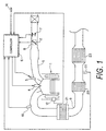
- Fig. 1 is a schematic view of an exhaust gas purification device according to this invention.
- Fig. 2 is a flowchart showing the details of NOx release/reduction processing.
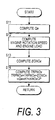
- Fig. 3 is a flowchart showing the details of a NOx trap amount computation processing.
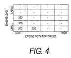
- Fig. 4 is a map for computing NOx concentration.
- Fig. 5 is a flowchart showing the details of an oxygen storage amount computation.
- Fig. 6 is a drawing showing the characteristics of an oxygen storage rate.
- Fig. 7 is a flowchart showing the details of another example of an oxygen storage amount computation processing (second embodiment).
- Fig. 8 is a flowchart showing the details of an excess oxygen amount computation processing.
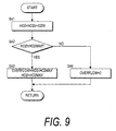
- Fig. 9 is a flowchart showing the details of a high-speed component computation processing.
- Fig. 10 is a flowchart showing the details of a low speed component computation processing.
- a throttle 2 is interposed in an intake air passage 5 of an engine 1, air adjusted by the throttle 2 being aspirated into the engine 1.
- This aspirated air is mixed with fuel injected by an injector 3 to form an air-fuel mixture.
- the injector 3 may inject the fuel into an intake port or may directly inject fuel into a combustion chamber of the engine 1.
- the air-fuel mixture in the combustion chamber is ignited by a spark plug 4 and burnt.
- the exhaust gas is purified by a first catalyst 21, second catalyst 22 and third catalyst 23 provided in an exhaust passage 9, and discharged into the atmosphere.
- the first catalyst 21 is a three-way catalyst which removes HC, CO discharged from the engine 1 when the engine starts up, and improves the exhaust gas purification performance.
- the first catalyst 21 is provided in the vicinity of the engine 1 so that it can rapidly attain an activation temperature.
- the second catalyst 22 is a NOx trap catalyst which traps NOx in the exhaust gas when the air-fuel ratio in the catalyst 22 is lean, and releases the trapped NOx when the air-fuel ratio in the catalyst 22 is the stoichiometric air-fuel ratio or a rich air-fuel ratio, and reduces the NOx in a three-way catalyst layer.
- the expression "the air-fuel ratio is lean” means that the air-fuel ratio is larger than the stoichiometric air-fuel ratio
- the expression "the air-fuel ratio is rich” means that the air-fuel ratio is smaller than the stoichiometric air-fuel ratio.
- the first catalyst 21 and second catalyst 22 store oxygen, and when it is stoichiometric or rich, they release the stored oxygen.
- the third catalyst 23 installed downstream of the NOx trap catalyst 22 is a three-way catalyst.
- the third catalyst 23 is used as a backup when NOx from the NOx trap catalyst 22 is released and reduced.
- a controller 6 which controls the injection timing and injection amount of the injector 3 and the ignition timing of the spark plug 4 comprises a microprocessor, memory and input/output interface.
- the controller 6 performs computation processing based on signals from sensors used for detecting running conditions described later, outputs a fuel injection signal (injection pulse signal) and injection timing to the injector 3, and outputs an ignition signal to the spark plug 4.
- a target air-fuel ratio is determined according to the running conditions, and a fuel injection amount (injection pulse width) is computed to give an air-fuel mixture having the target air-fuel ratio.
- the target air-fuel ratio is set to be leaner than the stoichiometric air-fuel ratio.
- the sensors which detect running conditions comprise an air flow meter 7 which detects the intake air flowrate of the engine 1, a throttle opening sensor 8 which detects the opening of the throttle 2, a first air-fuel ratio sensor 10 which is installed upstream of the first catalyst 21 and detects the exhaust gas air-fuel ratio, a second air-fuel ratio sensor 11 installed between the NOx trap catalyst 22 and third catalyst 23 which detects the exhaust gas air-fuel ratio, a crank angle sensor 14 which detects a rotation speed of the engine 1 and a water temperature sensor 12 which detects the cooling water temperature of the engine 1.
- the air-fuel ratio sensors 10, 11 are sensors which detect the exhaust gas air-fuel ratio based on the oxygen concentration in the exhaust gas.
- the air-fuel ratio sensors 10, 11 may be stoichiometric sensors which detect only the stoichiometric air-fuel ratio, or universal air-fuel ratio sensors which can detect the exhaust gas air-fuel ratio over a wide range.
- the controller 6 normally sets an air-fuel ratio feedback correction coefficient ⁇ by, for example, proportional/integral control so that the exhaust gas air-fuel ratio detected that the first air-fuel ratio sensor 10 approaches the target air-fuel ratio.
- the NOx amount which can be trapped by the NOx trap catalyst 22 is limited.
- the NOx trap rate decreases the more the trapped NOx amount increases, so when the trapped NOx amount increases to some extent, the air-fuel ratio in the catalyst is controlled to stoichiometric or rich, and the trapped NOx is released and reduced.
- the target air-fuel ratio of the engine 1 is temporarily shifted to rich, by determining the amount of reducing agent supplied due to this rich shift according to the oxygen amount stored in the catalysts 21, 22, the trapped NOx can be sufficiently released and reduced. Further, the oxygen amount stored by the catalysts 21, 22 is computed to high precision taking account of the conditions prior to NOx release/reduction processing.
- Fig. 2 is a flowchart showing the details of NOx release/reduction processing performed by the controller 6.
- a step S1 the generation of lean exhaust gas is determined by determining whether or not a flag FLEAN indicating lean running conditions is "1".
- the flag FLEAN is set to " 1 " when, for example, the output of the first air-fuel ratio sensor 10 has become leaner than the stoichiometric air-fuel ratio.
- the routine proceeds to a step S2, and a NOx amount TRPNOx trapped by the NOx trap catalyst 22 is computed.
- the computation of the NOx amount TRPNOx is performed according to the flowchart shown in Fig. 3.
- an intake air amount Qa is computed based on the output of the air flow meter 7 (step S11), and the engine rotation speed and engine load are computed based on the output of the crank angle sensor 14 and throttle opening sensor 8 (step S12).
- a NOx concentration EONOx in the engine exhaust gas is then computed, for example by looking up a map shown in Fig. 4, based on the computed engine rotation speed and load (step S13).
- TRPNOx TRPNOx + EONOx ⁇ Qa ⁇ K1 ⁇ KNOxCP
- K1 is a conversion constant and KNOxCP is a NOx trap rate which varies according to the conditions such as catalyst temperature, catalyst deterioration and present trapped NOx amount.
- a step S3 the computation of an oxygen amount OSCCNT stored in the catalysts 21, 22 is performed.
- the computation of the oxygen storage amount OSCCNT is performed according to the flowchart shown in Fig. 5.
- the intake air amount Qa is computed based on the output of the air flow meter 7 (step S15), and a present air-fuel ratio TFA of the engine 1 is read (step S16).
- the air-fuel ratio may be a value directly detected by the air-fuel ratio sensor 10, or it may be a target air-fuel ratio of the engine 1 computed by the controller 6.
- an oxygen amount FLWO2 flowing into the catalysts 21, 22 is calculated.
- the variation amount DOSCNT is computed by multiplying the oxygen amount flowing into the catalysts 21, 22 by a storage rate KOSCAP in the catalysts 21, 22.
- DOSCNT FLWO2 ⁇ KOSCAP
- the storage rate is a ratio between the oxygen amount newly stored by the catalyst to the oxygen amount flowing into the catalyst.
- the oxygen storage rate KOSCAP of the catalysts 21, 22 has the characteristics shown in Fig. 6 according to the oxygen amount which is already stored when lean running begins.
- the storage rate is represented by the gradient of the characteristic curve shown in Fig. 6. Up to a certain oxygen storage amount, the oxygen storage rate is high relative to the inflowing oxygen amount, then it falls to a low value. It becomes effectively zero at a certain storage amount.
- These characteristics may also be corrected for various conditions such as catalyst temperature and deterioration. For example, when the catalyst temperature is low and the catalyst has not yet been activated, or when the catalyst has deteriorated, the storage rate is corrected to the low side.
- the computation is performed separately for a region with a high storage rate and a region with a low storage rate according to the oxygen storage amount.
- the storage rate KOSCAP is set to TRK1
- the storage rate KOSCAP is set to TRK2 ( ⁇ TRK1 ).
- the value obtained by adding the variation amount DOSCNT of the oxygen storage amount to the oxygen storage amount OSCCNT on the immediately preceding occasion the computation was performed is set as the new oxygen storage amount OSCCNT (step S19).
- OSCCNT OSCCNT + DOSCNT
- a required reducing agent amount RICHF is computed by multiplying the oxygen storage amount OSCCNT by a constant K3.
- a step S5 it is determined whether or not rich shift start conditions are satisfied, based on a flag FRSPK .
- the flag FRSPK is set to "1".
- the air-fuel ratio correction coefficient is set to ⁇ sk , and the air-fuel ratio is shifted to rich.
- a step S8 the reducing agent amount RHCNT supplied until the present time is compared with the required reducing agent amount RICHF.
- the air-fuel ratio correction coefficient is left at ⁇ sk .
- the routine proceeds to a step S9, rich shift is terminated and the flag FRSPK is set to zero.
- a step S10 the counters ( RICHF , OSCCNT , TRPNOx , RHCNT ) are cleared, and the routine returns to ordinary air-fuel ratio control.
- the oxygen storage amount of the catalysts 21, 22 is computed separately for a region having a high oxygen storage rate and a region having a low oxygen storage rate (step S18) based on the characteristics wherein the oxygen storage rate varies according to the oxygen storage amount, the oxygen storage amount can be estimated with high precision even if the air-fuel ratio during lean running or lean running time is different.
- the NOx amount released from the catalyst 22 is affected by the oxygen amount stored in the catalysts 21, 22, but as a reducing agent amount corresponding to this oxygen storage amount is supplied (step S4, S6 through S8), the NOx trap catalyst 22 is maintained at the target air-fuel ratio, for example stoichiometric or a rich air-fuel ratio, and the trapped NOx can be released satisfactorily. Further, the supplied HC, CO are used for purifying the released NOx, so the discharge amounts of HC, CO into the atmosphere are suppressed to the absolute minimum.
- the required reducing agent amount RICHF was set to a value according to the oxygen storage amount of the catalysts 21, 22 (step S4), but as the reducing agent amount required to purify NOx becomes large even if the trapped NOx amount becomes large, the reducing agent supply amount may be computed taking account also of the trapped NOx amount TRPNOx in the catalyst 22.
- the required reducing agent amount RICHF computed in the step S4 may be a value obtained by adding a value obtained by multiplying the NOx amount TRPNOx by the constant K4 , to a value obtained by multiplying the oxygen storage amount OSCCNT by the constant K3.
- RICHF OSCCNT ⁇ K3 + TRPNOx ⁇ K4
- the method of computing the oxygen storage amount OSCCNT of the catalysts 21, 22 is different from that of the preceding embodiment.
- the oxygen amount stored by the catalysts 21, 22 may be separated into a high speed component stored/released by a noble metal (Pt, Rh, Pd) in the catalysts and a low speed component stored/released by an oxygen storage material in the catalyst.
- the oxygen storage amount is computed based on the fact that although the low speed component stores/releases a large amount of oxygen compared to the high speed component, its storage/release rate is slower than that of the high speed component.
- the computation is performed for the high speed component and low speed component assuming that, when oxygen is stored during lean running, first, oxygen is stored as the high speed component, and oxygen then begins to be stored as the low speed component when the high speed component reaches maximum capacity and oxygen can no longer be stored as the high speed component.
- the oxygen storage amount is calculated as the sum of this high speed component and low speed component.
- Fig. 7 shows the details of a main routine for computing an oxygen storage amount OSCCNT1 of the catalysts 21. This may be performed by the controller 6 instead of the computation routine shown in Fig. 5.
- step S21 various running parameters of the engine 1 are read, i.e., the output of the cooling water temperature sensor 12, crank angle sensor 14 and air flow meter 7.
- a subroutine (Fig. 8) for computing an excess oxygen amount O2IN is performed to compute the excess oxygen amount O2IN in the exhaust gas flowing into the catalyst 21.
- a subroutine (Fig. 9) for computing a high speed component HO2 is performed, and the high speed component HO2 and an overflow part OVERFLOW not stored as the high speed component HO2 are computed based on the excess oxygen amount O2IN .
- a step S24 it is determined whether or not the excess oxygen amount O2IN in exhaust gas flowing into the catalyst 21 was completely stored as the high speed component HO2 based on the overflow part OVERFLOW computed in the step S23.
- the routine proceeds to a step S26, otherwise the routine proceeds to a step S25 and a subroutine (Fig. 10) for computing a low speed component LO2, described later, is performed.
- step S26 the high speed component HO2 and low speed component LO2 computed as described above are added, and the oxygen storage amount OSCCNT1 of the catalyst 21 is thereby computed.
- Fig. 8 shows the subroutine for computing the excess oxygen amount O2IN in the exhaust gas flowing into the catalyst 21.
- the excess amount O2IN in the exhaust gas flowing into the catalyst 21 is computed based on the air-fuel ratio upstream of the catalyst 21 and the intake air amount of the engine 1.
- a step S31 the outputs of the first air-fuel ratio sensor 10 and air flow meter 7 are read.
- a step S32 the output of the first air-fuel ratio sensor 10 is converted to an air-fuel ratio using a predetermined conversion table, and the excess oxygen concentration in the exhaust gas flowing into the catalyst 21 is computed.
- the excess oxygen concentration is a relative concentration based on the oxygen concentration at the stoichiometric air-fuel ratio.
- a step S33 the output of the air flow meter 7 is converted to an intake air amount using a predetermined conversion table, and in a step S34, the excess oxygen amount O2IN in the exhaust gas flowing into the catalyst 21 is computed by multiplying the intake air amount computed in the step S33 by the excess oxygen concentration computed in the step S32.
- the excess oxygen concentration has the above characteristics, the excess oxygen amount O2IN is zero when the exhaust gas flowing into the catalyst 21 is at the stoichiometric air-fuel ratio, a negative value when it is rich, and a positive value when it is lean.
- Fig. 9 shows a subroutine for computing the high speed component HO2.
- the computation of the high speed component HO2 is performed based on the excess oxygen amount O2IN of the exhaust gas flowing into the catalyst 21.
- a step S42 it is determined whether or not this value exceeds a maximum capacity HO2MAX of the high speed component.
- the overflow part OVERFLOW which could not be stored as the high speed component HO2 , is stored as the low speed component LO2 .
- Fig. 10 shows a subroutine for computing the low speed component LO2 .
- the low speed component LO2 is computed based on the overflow part OVERFLOW which overflowed from the high speed component HO2 .
- the oxygen storage/release rate B of the low speed component is set to a positive value less than 1.
- the oxygen storage/release rate B actually has different characteristics for storage and release, and as the real storage/release rate is affected by the catalyst temperature and low speed component LO2 , etc., the storage rate and release rate may be set independently and variably. In this case, when the overflow part OVERFLOW is positive, oxygen is in excess. The oxygen storage rate B is then for example set to a larger value the higher the catalyst temperature or the smaller the low speed component LO2.
- a step S52 as in the case of the computation of the high speed component HO2 , it is determined whether or not the computed low speed component LO2 exceeds its maximum capacity LO2MAX . When it exceeds the maximum capacity LO2MAX , the routine proceeds to a step S53, and the low speed component LO2 is limited to the maximum capacity LO2MAX .
- This oxygen excess/deficiency amount flows out to the downstream catalyst 22.
- oxygen storage amount OSCCNT1 of the catalyst 21 has been computed in this way, and oxygen storage amount OSCCNT2 of the catalyst 22 is likewise computed separately for the high speed component HO2 low speed component (flowchart omitted), and the sum of the oxygen storage amount OSCCNT1 of the catalyst 21 and oxygen storage amount OSCCNT2 of the catalyst 22 is set to the oxygen storage amount OSCCNT .
- the oxygen storage amount OSCCNT2 of the catalyst 22 can be calculated using the oxygen excess/deficiency amount O2OUT calculated in the step S53 of Fig. 10.
- the oxygen storage amount OSCCNT is computed separately as the high speed component HO2 and low speed component LO2 in line with actual characteristics, so the oxygen amount OSCCNT stored by the catalysts 21, 22 can be computed with even higher precision.
- the required reducing agent according to the oxygen storage amount can be supplied more precisely, NOx trapped by the NOx trap catalyst can be released/reduced efficiently, and increase of CO, HC which are discharged into the atmosphere can be prevented.
- the methods of computing the trapped NOx amount and oxygen storage amount are not limited to those described here, and other methods may be used. Also, the construction of the exhaust gas purification device is not limited to that shown in Fig. 1, and may comprise a NOx trap catalyst together with a catalyst for storing oxygen which is installed upstream.
- the oxygen storage amount was computed for the catalysts 21, 22 together, but the oxygen storage amount may be computed separately for the catalyst 21 and catalyst 22. If the computation is performed separately, the precision of computing the oxygen storage amount is further improved, and the reducing agent required for release/reduction of NOx can be supplied with even less excess/deficiency.
Landscapes
- Engineering & Computer Science (AREA)
- Chemical & Material Sciences (AREA)
- Combustion & Propulsion (AREA)
- Mechanical Engineering (AREA)
- General Engineering & Computer Science (AREA)
- Chemical Kinetics & Catalysis (AREA)
- Health & Medical Sciences (AREA)
- General Chemical & Material Sciences (AREA)
- Biomedical Technology (AREA)
- Environmental & Geological Engineering (AREA)
- Analytical Chemistry (AREA)
- Oil, Petroleum & Natural Gas (AREA)
- Materials Engineering (AREA)
- Toxicology (AREA)
- Exhaust Gas After Treatment (AREA)
- Electrical Control Of Air Or Fuel Supplied To Internal-Combustion Engine (AREA)
- Exhaust Gas Treatment By Means Of Catalyst (AREA)
Applications Claiming Priority (2)
| Application Number | Priority Date | Filing Date | Title |
|---|---|---|---|
| JP2000261241 | 2000-08-30 | ||
| JP2000261241A JP3835140B2 (ja) | 2000-08-30 | 2000-08-30 | エンジンの空燃比制御装置 |
Publications (3)
| Publication Number | Publication Date |
|---|---|
| EP1184555A2 true EP1184555A2 (de) | 2002-03-06 |
| EP1184555A3 EP1184555A3 (de) | 2003-11-12 |
| EP1184555B1 EP1184555B1 (de) | 2006-01-11 |
Family
ID=18749119
Family Applications (1)
| Application Number | Title | Priority Date | Filing Date |
|---|---|---|---|
| EP01119941A Expired - Lifetime EP1184555B1 (de) | 2000-08-30 | 2001-08-17 | Abgasreinigungsvorrichtung für eine Brennkraftmaschine |
Country Status (4)
| Country | Link |
|---|---|
| US (1) | US6766640B2 (de) |
| EP (1) | EP1184555B1 (de) |
| JP (1) | JP3835140B2 (de) |
| DE (1) | DE60116554T2 (de) |
Cited By (3)
| Publication number | Priority date | Publication date | Assignee | Title |
|---|---|---|---|---|
| EP1508683A2 (de) | 2003-08-18 | 2005-02-23 | Volkswagen AG | Verfahren zum Betreiben einer Brennkraftmaschine |
| DE102007000359B4 (de) * | 2006-07-13 | 2013-04-18 | Denso Corporation | Abgasreinigungsvorrichtung für einen Verbrennungsmotor |
| WO2015135983A1 (de) * | 2014-03-13 | 2015-09-17 | Umicore Ag & Co. Kg | Katalysatorsystem für benzinverbrennungsmotoren mit dreiwegekatalysatoren und scr-katalysator |
Families Citing this family (16)
| Publication number | Priority date | Publication date | Assignee | Title |
|---|---|---|---|---|
| DE10039708A1 (de) * | 2000-08-14 | 2002-03-07 | Bosch Gmbh Robert | Verfahren und Modell zur Modellierung einer Ausspeicherphase eines Stickoxid-Speicherkatalysators |
| US6453661B1 (en) * | 2001-06-20 | 2002-09-24 | Ford Global Technologies, Inc. | System and method for determining target oxygen storage in an automotive catalyst |
| US6993899B2 (en) * | 2001-06-20 | 2006-02-07 | Ford Global Technologies, Llc | System and method for controlling catalyst storage capacity |
| JP3972748B2 (ja) * | 2002-07-03 | 2007-09-05 | トヨタ自動車株式会社 | 内燃機関の排気浄化装置 |
| WO2004097200A1 (ja) | 2003-04-30 | 2004-11-11 | Hitachi, Ltd. | 内燃機関の制御装置 |
| DE102004021372B4 (de) * | 2004-04-30 | 2014-05-28 | Robert Bosch Gmbh | Verfahren zum Dosieren eines Reagenzmittels zur Reinigung des Abgases von Brennkraftmaschinen und Vorrichtung zur Durchführung des Verfahrens |
| JP4759496B2 (ja) * | 2006-11-24 | 2011-08-31 | 本田技研工業株式会社 | 内燃機関の排ガス浄化装置 |
| US8474243B2 (en) * | 2006-12-22 | 2013-07-02 | Cummins, Inc. | System for controlling regeneration of an adsorber |
| JP5104323B2 (ja) * | 2008-01-10 | 2012-12-19 | 日産自動車株式会社 | エンジンの空燃比制御装置及び空燃比制御方法 |
| JP4877246B2 (ja) * | 2008-02-28 | 2012-02-15 | トヨタ自動車株式会社 | 内燃機関の空燃比制御装置 |
| EP2410146A4 (de) * | 2009-03-19 | 2013-05-29 | Toyota Motor Co Ltd | Abgasreinigungsvorrichtung für verbrennungsmotor |
| JP6244626B2 (ja) * | 2012-12-26 | 2017-12-13 | 日産自動車株式会社 | ディーゼルエンジンの排気後処理装置 |
| US10539058B2 (en) * | 2015-08-05 | 2020-01-21 | Cummins Emission Solutions Inc. | Oxygen correction for engine-out NOx estimates using a NOx sensor of an aftertreatment system |
| JP7047742B2 (ja) * | 2018-12-12 | 2022-04-05 | 株式会社デンソー | 状態推定装置 |
| WO2022064238A1 (ja) | 2020-09-25 | 2022-03-31 | 日産自動車株式会社 | 車両の制御方法及び車両の制御装置 |
| CN112539113B (zh) * | 2020-11-30 | 2023-01-06 | 潍柴动力股份有限公司 | 一种空气系统控制方法及装置 |
Family Cites Families (18)
| Publication number | Priority date | Publication date | Assignee | Title |
|---|---|---|---|---|
| EP0898067B1 (de) | 1997-08-21 | 2004-03-17 | Nissan Motor Co., Ltd. | Abgasreinigungssystem für eine Brennkraftmaschine |
| JP3446582B2 (ja) * | 1998-01-14 | 2003-09-16 | 日産自動車株式会社 | エンジンの排気浄化装置 |
| DE19801626B4 (de) * | 1998-01-17 | 2010-08-12 | Robert Bosch Gmbh | Diagnose eines NOx-Speicherkatalysators beim Betrieb von Verbrennungsmotoren |
| DE19801625A1 (de) * | 1998-01-17 | 1999-07-22 | Bosch Gmbh Robert | Diagnose eines NOx-Speicherkatalysators beim Betrieb von Verbrennungsmotoren |
| JP3663896B2 (ja) * | 1998-03-18 | 2005-06-22 | 日産自動車株式会社 | エンジンの排気浄化装置 |
| DE19816175A1 (de) * | 1998-04-14 | 1999-10-21 | Degussa | Verfahren zur Überprüfung der Funktionstüchtigkeit eines Stickoxid-Speicherkatalysators |
| DE59910881D1 (de) * | 1998-06-20 | 2004-11-25 | Daimler Chrysler Ag | Regelstrategie für einen NOx-Speicher |
| JP3478135B2 (ja) | 1998-08-06 | 2003-12-15 | トヨタ自動車株式会社 | 内燃機関の排気浄化装置 |
| US6336320B1 (en) * | 1998-07-10 | 2002-01-08 | Toyota Jidosha Kabushiki Kaisha | Exhaust gas purification device for an internal combustion engine |
| US6289672B1 (en) * | 1998-07-21 | 2001-09-18 | Toyota Jidosha Kabushiki Kaisha | Exhaust gas purification device for an internal combustion engine |
| JP3572961B2 (ja) * | 1998-10-16 | 2004-10-06 | 日産自動車株式会社 | エンジンの排気浄化装置 |
| EP0997617A1 (de) * | 1998-10-28 | 2000-05-03 | Ford Global Technologies, Inc., A subsidiary of Ford Motor Company | Verfahren zur Regeneration einer Stickoxidfalle im Abgassystem eines Verbrennungsmotors sowie Vorrichtung zur Durchführung des Verfahrens |
| JP3649034B2 (ja) * | 1999-03-25 | 2005-05-18 | 日産自動車株式会社 | エンジンの排気浄化装置 |
| JP3536764B2 (ja) * | 2000-02-14 | 2004-06-14 | 日産自動車株式会社 | エンジンの排気浄化装置 |
| US6308697B1 (en) * | 2000-03-17 | 2001-10-30 | Ford Global Technologies, Inc. | Method for improved air-fuel ratio control in engines |
| US6427437B1 (en) * | 2000-03-17 | 2002-08-06 | Ford Global Technologies, Inc. | Method for improved performance of an engine emission control system |
| US6327847B1 (en) * | 2000-03-17 | 2001-12-11 | Ford Global Technologies, Inc. | Method for improved performance of a vehicle |
| US6418711B1 (en) * | 2000-08-29 | 2002-07-16 | Ford Global Technologies, Inc. | Method and apparatus for estimating lean NOx trap capacity |
-
2000
- 2000-08-30 JP JP2000261241A patent/JP3835140B2/ja not_active Expired - Lifetime
-
2001
- 2001-08-17 DE DE60116554T patent/DE60116554T2/de not_active Expired - Lifetime
- 2001-08-17 EP EP01119941A patent/EP1184555B1/de not_active Expired - Lifetime
- 2001-08-20 US US09/931,773 patent/US6766640B2/en not_active Expired - Lifetime
Cited By (5)
| Publication number | Priority date | Publication date | Assignee | Title |
|---|---|---|---|---|
| EP1508683A2 (de) | 2003-08-18 | 2005-02-23 | Volkswagen AG | Verfahren zum Betreiben einer Brennkraftmaschine |
| EP1508683A3 (de) * | 2003-08-18 | 2007-01-03 | Volkswagen AG | Verfahren zum Betreiben einer Brennkraftmaschine |
| DE102007000359B4 (de) * | 2006-07-13 | 2013-04-18 | Denso Corporation | Abgasreinigungsvorrichtung für einen Verbrennungsmotor |
| WO2015135983A1 (de) * | 2014-03-13 | 2015-09-17 | Umicore Ag & Co. Kg | Katalysatorsystem für benzinverbrennungsmotoren mit dreiwegekatalysatoren und scr-katalysator |
| US10022672B2 (en) | 2014-03-13 | 2018-07-17 | Umicore Ag & Co. Kg | Catalyst system for gasoline combustion engines, having three-way catalysts and SCR catalyst |
Also Published As
| Publication number | Publication date |
|---|---|
| US6766640B2 (en) | 2004-07-27 |
| JP2002070611A (ja) | 2002-03-08 |
| JP3835140B2 (ja) | 2006-10-18 |
| US20020023432A1 (en) | 2002-02-28 |
| EP1184555B1 (de) | 2006-01-11 |
| DE60116554D1 (de) | 2006-04-06 |
| EP1184555A3 (de) | 2003-11-12 |
| DE60116554T2 (de) | 2006-11-16 |
Similar Documents
| Publication | Publication Date | Title |
|---|---|---|
| US6766640B2 (en) | Engine exhaust purification device | |
| US6622478B2 (en) | Engine exhaust purification device | |
| EP0908613A2 (de) | Abgassteuerungssystem für Brennkraftmaschine mit NOx-Katalysator | |
| US6185933B1 (en) | Exhaust emission control device for engine | |
| US6546719B2 (en) | Air-fuel ratio control apparatus of internal combustion engine | |
| JP3672081B2 (ja) | 内燃機関の排ガス浄化装置 | |
| US6564544B2 (en) | Engine exhaust purification arrangement | |
| EP1128042B1 (de) | Abgasreinigungssystem einer Brennkraftmaschine | |
| JP3778012B2 (ja) | 内燃機関の空燃比制御装置 | |
| JP7044022B2 (ja) | 排気浄化システムの制御装置 | |
| JP4031887B2 (ja) | エンジンの空燃比制御装置および方法 | |
| JP6809004B2 (ja) | 内燃機関 | |
| JP4608758B2 (ja) | 内燃機関の空燃比制御装置 | |
| JP2000130221A (ja) | 内燃機関の燃料噴射制御装置 | |
| JP4269279B2 (ja) | 内燃機関の制御装置 | |
| US6650991B2 (en) | Closed-loop method and system for purging a vehicle emission control | |
| JP2001098981A (ja) | 内燃機関の触媒劣化判定装置 | |
| JP4666542B2 (ja) | 内燃機関の排気浄化制御装置 | |
| JP2526595B2 (ja) | 内燃機関の空燃比制御装置 | |
| JP2526568B2 (ja) | 内燃機関の空燃比制御装置 | |
| JPH0660579B2 (ja) | エンジンの燃料制御装置 | |
| JP2004346862A (ja) | 内燃機関 | |
| JP2002089249A (ja) | 内燃機関の排気浄化装置 | |
| JP3800049B2 (ja) | エンジンの排気浄化装置 | |
| JPH11117791A (ja) | 内燃機関の空燃比制御装置 |
Legal Events
| Date | Code | Title | Description |
|---|---|---|---|
| PUAI | Public reference made under article 153(3) epc to a published international application that has entered the european phase |
Free format text: ORIGINAL CODE: 0009012 |
|
| 17P | Request for examination filed |
Effective date: 20010817 |
|
| AK | Designated contracting states |
Kind code of ref document: A2 Designated state(s): AT BE CH CY DE DK ES FI FR GB GR IE IT LI LU MC NL PT SE TR |
|
| AX | Request for extension of the european patent |
Free format text: AL;LT;LV;MK;RO;SI |
|
| RIN1 | Information on inventor provided before grant (corrected) |
Inventor name: ISHIZUKA, YASUJI Inventor name: YOSHIOKA, YOSHIAKI Inventor name: TAKAHASHI, HIDEAKI |
|
| PUAL | Search report despatched |
Free format text: ORIGINAL CODE: 0009013 |
|
| AK | Designated contracting states |
Kind code of ref document: A3 Designated state(s): AT BE CH CY DE DK ES FI FR GB GR IE IT LI LU MC NL PT SE TR |
|
| AX | Request for extension of the european patent |
Extension state: AL LT LV MK RO SI |
|
| AKX | Designation fees paid |
Designated state(s): DE FR GB |
|
| 17Q | First examination report despatched |
Effective date: 20040628 |
|
| GRAP | Despatch of communication of intention to grant a patent |
Free format text: ORIGINAL CODE: EPIDOSNIGR1 |
|
| GRAS | Grant fee paid |
Free format text: ORIGINAL CODE: EPIDOSNIGR3 |
|
| GRAA | (expected) grant |
Free format text: ORIGINAL CODE: 0009210 |
|
| AK | Designated contracting states |
Kind code of ref document: B1 Designated state(s): DE FR GB |
|
| REF | Corresponds to: |
Ref document number: 60116554 Country of ref document: DE Date of ref document: 20060406 Kind code of ref document: P |
|
| ET | Fr: translation filed | ||
| PLBE | No opposition filed within time limit |
Free format text: ORIGINAL CODE: 0009261 |
|
| STAA | Information on the status of an ep patent application or granted ep patent |
Free format text: STATUS: NO OPPOSITION FILED WITHIN TIME LIMIT |
|
| 26N | No opposition filed |
Effective date: 20061012 |
|
| REG | Reference to a national code |
Ref country code: FR Ref legal event code: PLFP Year of fee payment: 16 |
|
| REG | Reference to a national code |
Ref country code: FR Ref legal event code: PLFP Year of fee payment: 17 |
|
| REG | Reference to a national code |
Ref country code: FR Ref legal event code: PLFP Year of fee payment: 18 |
|
| PGFP | Annual fee paid to national office [announced via postgrant information from national office to epo] |
Ref country code: GB Payment date: 20200805 Year of fee payment: 20 Ref country code: DE Payment date: 20200804 Year of fee payment: 20 Ref country code: FR Payment date: 20200715 Year of fee payment: 20 |
|
| REG | Reference to a national code |
Ref country code: DE Ref legal event code: R071 Ref document number: 60116554 Country of ref document: DE |
|
| REG | Reference to a national code |
Ref country code: GB Ref legal event code: PE20 Expiry date: 20210816 |
|
| PG25 | Lapsed in a contracting state [announced via postgrant information from national office to epo] |
Ref country code: GB Free format text: LAPSE BECAUSE OF EXPIRATION OF PROTECTION Effective date: 20210816 |