EP1184662A1 - Photometre a balayage en longueur d'onde d'emission a filtre antiparasite - Google Patents
Photometre a balayage en longueur d'onde d'emission a filtre antiparasite Download PDFInfo
- Publication number
- EP1184662A1 EP1184662A1 EP01906343A EP01906343A EP1184662A1 EP 1184662 A1 EP1184662 A1 EP 1184662A1 EP 01906343 A EP01906343 A EP 01906343A EP 01906343 A EP01906343 A EP 01906343A EP 1184662 A1 EP1184662 A1 EP 1184662A1
- Authority
- EP
- European Patent Office
- Prior art keywords
- interference filter
- component
- wavelength
- transmission wavelength
- zero cross
- Prior art date
- Legal status (The legal status is an assumption and is not a legal conclusion. Google has not performed a legal analysis and makes no representation as to the accuracy of the status listed.)
- Granted
Links
Images


Classifications
-
- G—PHYSICS
- G01—MEASURING; TESTING
- G01J—MEASUREMENT OF INTENSITY, VELOCITY, SPECTRAL CONTENT, POLARISATION, PHASE OR PULSE CHARACTERISTICS OF INFRARED, VISIBLE OR ULTRAVIOLET LIGHT; COLORIMETRY; RADIATION PYROMETRY
- G01J3/00—Spectrometry; Spectrophotometry; Monochromators; Measuring colours
- G01J3/02—Details
- G01J3/06—Scanning arrangements arrangements for order-selection
-
- G—PHYSICS
- G01—MEASURING; TESTING
- G01J—MEASUREMENT OF INTENSITY, VELOCITY, SPECTRAL CONTENT, POLARISATION, PHASE OR PULSE CHARACTERISTICS OF INFRARED, VISIBLE OR ULTRAVIOLET LIGHT; COLORIMETRY; RADIATION PYROMETRY
- G01J3/00—Spectrometry; Spectrophotometry; Monochromators; Measuring colours
- G01J3/12—Generating the spectrum; Monochromators
- G01J3/26—Generating the spectrum; Monochromators using multiple reflection, e.g. Fabry-Perot interferometer, variable interference filters
-
- G—PHYSICS
- G01—MEASURING; TESTING
- G01N—INVESTIGATING OR ANALYSING MATERIALS BY DETERMINING THEIR CHEMICAL OR PHYSICAL PROPERTIES
- G01N21/00—Investigating or analysing materials by the use of optical means, i.e. using sub-millimetre waves, infrared, visible or ultraviolet light
- G01N21/17—Systems in which incident light is modified in accordance with the properties of the material investigated
- G01N21/25—Colour; Spectral properties, i.e. comparison of effect of material on the light at two or more different wavelengths or wavelength bands
- G01N21/31—Investigating relative effect of material at wavelengths characteristic of specific elements or molecules, e.g. atomic absorption spectrometry
- G01N21/314—Investigating relative effect of material at wavelengths characteristic of specific elements or molecules, e.g. atomic absorption spectrometry with comparison of measurements at specific and non-specific wavelengths
- G01N2021/317—Special constructive features
Definitions
- the present invention relates to a convenient and cheap analytical apparatus for determining concentration of an interesting component in a sample without interfering of the coexistent components by applying light absorption of the interesting component.
- the present invention relates to the convenient and cheap analytical apparatus which is realized by the procedures of:
- the simplest method is to measure intensity changes of a monochromatic light transmitting through the sample in which the interesting component absorbing the monochromatic light is contained.
- an ultraviolet absorption photometer for monitoring water quality is well-known.
- This photometer utilizes a phenomenon that an organic waste in water absorbs light of 253.7 nm from a mercury lamp and it consists of a light source, a sample cell, a detector and an amplifier.
- this method that is called single beam method, we have often measuring error because an interfering value by the intensity change of the light source is not able to differ from measuring value by the light absorption of the organic waste.
- Double beam method which removes this defect of the single beam method.
- a beam from a light source splits into two beams, that is, one for a sensing beam and other for a reference beam, and the measuring value is obtained as difference or ratio between those intensities. It means that the intensity change of the sensing beam is standardized by the intensity of the reference beam.
- the intensity change of the light source does not affect the measuring results.
- Double wavelength spectrometry is another method not to affect the measuring results by the intensity change of the light source.
- two different monochromatic beams are alternately transmitted through or reflected on a sample, and absorption intensity of an interesting component in the sample is obtained by measuring difference or ratio between those intensities.
- Wavelength of the one monochromatic beam for reference is selected different from an absorption wavelength of the interesting component, and wavelength of the other monochromatic beam for sensing is equal to the absorption wavelength of the interesting component, and the intensity change of the monochromatic beam for sensing is standardized by the intensity of the monochromatic beam for reference, therefore, this method has no measuring error by the intensity change of the light source.
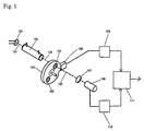
- Figure 1 is a block diagram of a filter correlation infrared analyzer, in which infrared beam 121 radiated from an infrared source 101 transmits through a sample cell 102, and an infrared beam after transmitting 122 goes ahead to a modulator 103.
- the sample cell 102 is a pipe, which is put infrared transmission windows on both ends, and an inlet and an outlet on the near places from the both ends.
- An interesting component in sample gas flowing through the sample cell absorbs infrared of specific wavelength, and the infrared beam after transmitting 122 loses the energy at the specific wavelength.
- the modulator 103 is a rotating disk mounting filters, and one of those is a sensing filter 104 whose maximum transmission wavelength is equal to the specific wavelength absorbed by the interesting component, and other is a reference filer 105 whose maximum transmission wavelength is different from the specific wavelength.
- the filters cross the infrared beam after transmitting 122 periodically.
- the infrared beam after transmitting 122 is modulated like that the beam transmits through the sensing filter 104 and the reference filter 105 alternately.
- the modulated infrared beam 123 focuses on an infrared sensor 108 by a focusing lens 107, and is detected as an electric signal.
- the detected electric signal is amplified by a head amplifier 110, and is put in a synchronous rectifier 111.
- a synchronous signal detector 106 detects a synchronous signal of the modulator, and puts the synchronous signal in a phase adjuster 109.
- the phase adjuster adjusts the synchronous signal and puts the signal in the synchronous rectifier 111.
- the synchronous rectifier 111 rectifies the electric signal synchronizing with the synchronous signal, and obtains measuring signal corresponding to the concentration of the interesting component in the sample.
- the gaseous or liquid samples contain many coexisting components with the interesting component. Some of the components interfere to analyze the interesting component, such as water vapor in the case of analyzing nitrogen mono-oxide in flue gas and water or electrolyte in water in the case of analyzing glucose dissolved in water.
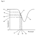
- a spectrum of interfering components 152 has no peak at an absorption wavelength of the interesting component 153 but tails over it. Even if slope of the tailing is small, the tailing often gives analyzing results fatal errors according to increasing concentration of the interfering components.
- the double wavelength spectrometry often has problem that the tailing of spectrum of the interfering components gives analyzing results fatal errors, even if reference wavelength 154 is selected near the absorption wavelength of the interesting component 153.
- an objective of the present invention provides an analyzing apparatus which removes the interfering by the tailing spectrum of the interfering components and determines exact concentration of the interesting component by applying the light absorption of the interesting component. It is a further objective of the present invention to provide a convenient and cheap analyzing apparatus measuring non-destructively and non-invasively to a person.
- the present invention provides an interference filter transmission wavelength scanning photometer for determining concentration of an interesting component in a sample without interfering of the coexistent components by applying the light absorption of the interesting component comprising:
- the photometer of the present invention can determine concentration of an interesting component in a sample without interfering of the coexistent components by operations comprising the following steps.
- Deciding range of scanning the transmission wavelength of said interference filter so that center of small change of wavelength induced by scanning the transmission wavelength periodically is equal to an absorption wavelength of said interesting component
- Figure 1 is a block diagram of a filter correlation infrared analyzer as an example of prior art.
- Figure 2 is a spectrogram showing a relation between a spectrum of an interesting component and one of interfering components.
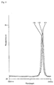
- Figure 3 is a spectrogram showing spectra of an interference filter when inclining its normal to the optical axis
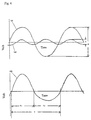
- Figure 4 is a chart showing relation between an electrical signal due to an interesting component and one due to interfering components.
- Figure 5 is a block diagram showing the preferred embodiment of an interference filter transmission wavelength scanning photometer of the present invention.
- Figure 6 is a sketch illustrating optical sampling system by which an optical signal about concentration of glucose in blood is obtained from human lip.
- Figure 7 is a spectrogram of main components of which a sample is composed for working example of the present invention.
- Figure 8 is a correlation plot of measuring values by an interference filter transmission wavelength scanning photometer of the present invention to glucose concentration in human blood measured by a commercial glucose meter.
- an interference filter is swung periodically to incline a normal of the interference filter to an optical axis and thereby, the peak transmission wavelength of the interference filter is scanned in narrow range between a short wavelength limit 161 and a long wavelength limit 162 around an absorption wavelength of an interesting component 153 in a sample as shown in figure 2.
- the transmission wavelength is changed by inclining the normal of the interference filter to the optical axis.
- Figure 3 shows experimental spectra 171,172 and 173 of an interference filter which is inclined at the angle of 15, 20 and 25 degree between its normal and the optical axis.
- the maximum transmission wavelengths are 2289 nm, 2273 nm and 2257 nm respectively. (Scale of horizontal axis of all spectrogram are linear to wave numbers but all numerical expressions are converted into wavelength for consistent description.)
- Transmittance which is observed after light beam transmits through the sample having a spectrum of interfering components shown in figure 2 varies periodically from a high transmittance limit 163 to a low transmittance limit 164, by change of the maximum transmission wavelength from the short wavelength limit 161 at the angle of 25 degree to the long wavelength limit 162 at the angle of 15 degree.
- An electric signal which is proportional to the intensity of the light beam transmitting through the sample is detected by an infrared sensor, and it is varied periodically like an electric signal due to the interfering component 181 in figure 4.
- the electric signal due to the interfering component 181 takes maximum value to positive when the angle is 25 degree, that is, at the high transmittance limit 163 and minimum value to negative when the angle is 15 degree, that is, at the low transmittance limit 164.
- an actual observed signal 183 is synthetic electrical signal which is sum of the electric signal due to the interfering components 181 and the electric signal due to the interesting component 182.
- the information which has to be obtained is about the amplitude of the electric signal due to the interesting component 182.
- time lags at the zero cross points are estimated when letting the electric signal F at zero cross points down as the variation of (1/2) ⁇ .
- the electric signal F is differentiated as the below equation for obtaining slopes of the electric signal F at the zero cross points.
- T 2 - T 1 ⁇ T/( ⁇ A)
- concentration of the interesting component without the interfering of coexisting components by examining in the full period(T) and the one half period(T1), as the another half period T 2 can calculate as the difference of the full period T and the one half period T 1 .
- FIG 5 is separated two parts, that is, one is a diagram of an optical layout and another is a block diagram of electric circuits.
- shorter wavelengths of the light beam from a light source 1 is cut off by a long wavelength pass filter 2, and longer wavelengths of the light beam passes through the filter and goes ahead to an interference filter 3.
- the interference filter 3 is fixed with forcing coils 7 and can swing centering an axis 4.
- S-poles 5 and N-poles 6 of a magnet are installed on the both side of wirings of the forcing coils 7 and by giving the forcing coils 7 alternating current, the interference filter starts to swing centering the axis 4.
- the angle between the normal of the interference filter and the optical axis is initially set at the angle of 20 degree so that the angle changed by the swinging is within the angle from 15 to 25 degree.
- the quartz rod 9 guides the light beam near to a sample 10, and the light beam from another end surface of the quartz rod irradiates the sample 10.
- Part of the light beam reflected on the surface of the sample is put in an infrared sensor 11.
- the light beam which is modulated by swinging the interference filter and reflected on the sample 10 is detected by the infrared sensor 11 as electric signal.
- the electric signal is sent to the part of the electric circuits.
- an oscillation circuit which supplies alternative current to the forcing coils 7 for swinging the interference filter 3. It is extremely important to keep swinging the interference filter stable because swinging the interference filter forced by the alternative current is origin of all signals. Therefore, a feedback control system is adopted to keep the energy swinging the interference filter constant, measuring the swinging velocity by putting sensing coils at the same position of the forcing coils.
- the electric signal which is induced in the optical system and detected by the infrared sensor 11 is amplified by head amplifier 13, and its AC component is amplified by an alternative amplifier 14 and put in a zero cross detector 15, having basic frequency decided by the swinging frequency of the interference filter.
- the zero cross detector generates interrupt signal which informs a microprocessor 16 times when the rising or falling electric signals cross zero level.
- the microprocessor 16 memorizes the times of every zero cross points by aid of an inner timer.
- the full period T is obtained as the time from the rising zero cross point to the next rising zero cross point and the half period T 1 as the time from the rising zero cross point to the falling zero cross point.
- a remainder obtained by subtracting twice value of an integrated half period ⁇ T 1 from an integrated full period ⁇ T divided by the integrated full period ⁇ T gives a ratio that is defined distortion factor here.
- concentration of the interesting component for instance, glucose concentration in blood for glucose meter
- concentration of the interesting component is determined by the distortion factor and its value is displayed and communicated.
- a display device 17 which displays concentration value etc., a key board by which the apparatus is operated and a communication port 19 through which many information including the measuring value can be communicated are mounted with the microprocessor.
- the human lip has mass of the capillary blood vessels under the outermost skin, and the red lip is visible to the naked eye.
- the interference filter transmission wavelength scanning photometer of the present invention is applied for determining the glucose concentration in the blood by diffuse reflectance on this surface.
- An optical sampling system is shown in figure 6.
- Quartz_rod 31 is the same part signed 9 in figure 5.
- Header 32 holds the quartz rod which guides the light beam to the human lip 34 and an infrared sensor 33 which detects the reflecting light on the human lip 34.
- a suction pump 35 with a suction pressure regulator 36 sucks a cavity between the human lip 34 and the infrared sensor 33, to stick the surface of the human lip 34 on the header 32.
- Figure 7 is shown spectra of the main components in the blood, in which a spectrum of water is signed by A, a spectrum of blood paste removed the water from the blood by B and a difference spectrum of the glucose in the water obtained by subtracting the spectrum of the water by C.
- a prototype of the interference filter transmission wavelength scanning photometer has been trially manufactured and by using this prototype, the glucose concentration in blood has been determined non-invasively.
- Data for each data integrating time are divided to ten sections and distortion factors for the sections are calculated.
- a measuring value for each data integrating time is an average of six medians from ten calculated distortion factors.
- the glucose concentration in the blood of a healthy test person with an empty stomach has been 89 mg/dL measured by a commercial glucose meter.
- the interference filter transmission wavelength scanning photometer of the present invention has been applied for determining the glucose concentration in the blood, and five measuring values have been obtained. Consequently, between 40 minute later and 70 minute later from the time when the test person drank a cup of syrup which was hot water dissolved glucose of 75 g, three measuring values have been obtained. At 60 minute later from the time when the test person drank a cup of the syrup, the glucose concentration in the blood of the test person has been 308 mg/dL measured by the commercial glucosemeter.
- Determination of the concentration of the interesting component by applying the light absorption of the material has desirable features such as non-destructive and non-invasive to person. But in many cases, as the tailing of the spectra of coexisting components overlaps the absorption wavelength of the interesting component, it is difficult to determine concentration of the interesting component by using only one wavelength. Therefore many wavelengths are used for the determination, after all a spectrometry is applied for it. Although such a spectrometry has wide application fields, it needs large equipment and expensive cost. With these reasons, the analyzing apparatus by applying the light absorption of the material is desirable, but is not used so commonly. For example, there is no glucose meter by applying the light absorption of the material in Japanese market, although many glucose meters by enzymatic method are commonly used.
- the present invention is able to achieve same performance as the spectrometry for one component in the sample by a simple composition.
- the present invention is industrially valuable, because picking up a desirable feature for determining the concentration of the interesting component by applying the light absorption of the material, developing to the way to make analytical apparatus good performance to cost, and contributing technically to industrial fields, environmental pollution control, and medical fields.
Landscapes
- Physics & Mathematics (AREA)
- Spectroscopy & Molecular Physics (AREA)
- General Physics & Mathematics (AREA)
- Health & Medical Sciences (AREA)
- Life Sciences & Earth Sciences (AREA)
- Chemical & Material Sciences (AREA)
- Analytical Chemistry (AREA)
- Biochemistry (AREA)
- General Health & Medical Sciences (AREA)
- Immunology (AREA)
- Pathology (AREA)
- Investigating Or Analysing Materials By Optical Means (AREA)
Applications Claiming Priority (3)
| Application Number | Priority Date | Filing Date | Title |
|---|---|---|---|
| JP2000051329 | 2000-02-28 | ||
| JP2000051329 | 2000-02-28 | ||
| PCT/JP2001/001455 WO2001063249A1 (fr) | 2000-02-28 | 2001-02-27 | Photometre a balayage en longueur d'onde d'emission a filtre antiparasite |
Publications (3)
| Publication Number | Publication Date |
|---|---|
| EP1184662A1 true EP1184662A1 (fr) | 2002-03-06 |
| EP1184662A4 EP1184662A4 (fr) | 2004-09-08 |
| EP1184662B1 EP1184662B1 (fr) | 2006-04-26 |
Family
ID=18572991
Family Applications (1)
| Application Number | Title | Priority Date | Filing Date |
|---|---|---|---|
| EP01906343A Expired - Lifetime EP1184662B1 (fr) | 2000-02-28 | 2001-02-27 | Photometre a balayage en longueur d'onde d'emission a filtre antiparasite |
Country Status (4)
| Country | Link |
|---|---|
| US (1) | US6747276B2 (fr) |
| EP (1) | EP1184662B1 (fr) |
| DE (1) | DE60119050T2 (fr) |
| WO (1) | WO2001063249A1 (fr) |
Cited By (2)
| Publication number | Priority date | Publication date | Assignee | Title |
|---|---|---|---|---|
| US9442065B2 (en) | 2014-09-29 | 2016-09-13 | Zyomed Corp. | Systems and methods for synthesis of zyotons for use in collision computing for noninvasive blood glucose and other measurements |
| US9554738B1 (en) | 2016-03-30 | 2017-01-31 | Zyomed Corp. | Spectroscopic tomography systems and methods for noninvasive detection and measurement of analytes using collision computing |
Families Citing this family (13)
| Publication number | Priority date | Publication date | Assignee | Title |
|---|---|---|---|---|
| US7846131B2 (en) * | 2005-09-30 | 2010-12-07 | Covidien Ag | Administration feeding set and flow control apparatus with secure loading features |
| US7722573B2 (en) * | 2006-03-02 | 2010-05-25 | Covidien Ag | Pumping apparatus with secure loading features |
| US7758551B2 (en) * | 2006-03-02 | 2010-07-20 | Covidien Ag | Pump set with secure loading features |
| US8021336B2 (en) | 2007-01-05 | 2011-09-20 | Tyco Healthcare Group Lp | Pump set for administering fluid with secure loading features and manufacture of component therefor |
| US7763005B2 (en) | 2006-03-02 | 2010-07-27 | Covidien Ag | Method for using a pump set having secure loading features |
| US7927304B2 (en) | 2006-03-02 | 2011-04-19 | Tyco Healthcare Group Lp | Enteral feeding pump and feeding set therefor |
| US7722562B2 (en) | 2006-03-02 | 2010-05-25 | Tyco Healthcare Group Lp | Pump set with safety interlock |
| US7560686B2 (en) * | 2006-12-11 | 2009-07-14 | Tyco Healthcare Group Lp | Pump set and pump with electromagnetic radiation operated interlock |
| US20080147008A1 (en) * | 2006-12-15 | 2008-06-19 | Tyco Healthcare Group Lp | Optical detection of medical pump rotor position |
| US8154274B2 (en) | 2010-05-11 | 2012-04-10 | Tyco Healthcare Group Lp | Safety interlock |
| KR101716663B1 (ko) * | 2015-12-09 | 2017-03-15 | (주)아이에스엠아이엔씨 | 무채혈 혈당 측정 보정 방법 및 장치 |
| EP3460456B1 (fr) | 2017-09-20 | 2020-08-26 | IMEC vzw | Système biocapteur permettant de détecter une lumière fluorescente d'angle supercritique |
| EP3705875B1 (fr) | 2019-03-05 | 2022-11-30 | IMEC vzw | Appareil et procédé de détection de la lumière photoluminescente émise à partir d'un échantillon |
Family Cites Families (6)
| Publication number | Priority date | Publication date | Assignee | Title |
|---|---|---|---|---|
| DE2530480A1 (de) * | 1975-07-09 | 1977-01-27 | Bayer Ag | Einstrahlphotometer |
| GB2148492B (en) * | 1983-10-22 | 1986-10-22 | Stc Plc | Gas detector |
| US4752129A (en) * | 1985-03-27 | 1988-06-21 | Anritsu Corporation | Wavelength modulation derivative spectrometer |
| JPH067099B2 (ja) * | 1989-03-14 | 1994-01-26 | 東邦瓦斯株式会社 | チューナブルエタロンを用いたガスセンサ |
| EP0510856A3 (en) * | 1991-04-26 | 1993-12-22 | Siemens Plessey Controls Ltd | Improvements in or relating to optical gas detectors |
| JPH05267770A (ja) * | 1992-03-18 | 1993-10-15 | Anritsu Corp | 波長安定化装置付光源 |
-
2001
- 2001-02-27 WO PCT/JP2001/001455 patent/WO2001063249A1/fr not_active Ceased
- 2001-02-27 US US09/959,454 patent/US6747276B2/en not_active Expired - Fee Related
- 2001-02-27 EP EP01906343A patent/EP1184662B1/fr not_active Expired - Lifetime
- 2001-02-27 DE DE60119050T patent/DE60119050T2/de not_active Expired - Lifetime
Cited By (9)
| Publication number | Priority date | Publication date | Assignee | Title |
|---|---|---|---|---|
| US9442065B2 (en) | 2014-09-29 | 2016-09-13 | Zyomed Corp. | Systems and methods for synthesis of zyotons for use in collision computing for noninvasive blood glucose and other measurements |
| US9448164B2 (en) | 2014-09-29 | 2016-09-20 | Zyomed Corp. | Systems and methods for noninvasive blood glucose and other analyte detection and measurement using collision computing |
| US9448165B2 (en) | 2014-09-29 | 2016-09-20 | Zyomed Corp. | Systems and methods for control of illumination or radiation collection for blood glucose and other analyte detection and measurement using collision computing |
| US9453794B2 (en) | 2014-09-29 | 2016-09-27 | Zyomed Corp. | Systems and methods for blood glucose and other analyte detection and measurement using collision computing |
| US9459201B2 (en) | 2014-09-29 | 2016-10-04 | Zyomed Corp. | Systems and methods for noninvasive blood glucose and other analyte detection and measurement using collision computing |
| US9459202B2 (en) | 2014-09-29 | 2016-10-04 | Zyomed Corp. | Systems and methods for collision computing for detection and noninvasive measurement of blood glucose and other substances and events |
| US9459203B2 (en) | 2014-09-29 | 2016-10-04 | Zyomed, Corp. | Systems and methods for generating and using projector curve sets for universal calibration for noninvasive blood glucose and other measurements |
| US9610018B2 (en) | 2014-09-29 | 2017-04-04 | Zyomed Corp. | Systems and methods for measurement of heart rate and other heart-related characteristics from photoplethysmographic (PPG) signals using collision computing |
| US9554738B1 (en) | 2016-03-30 | 2017-01-31 | Zyomed Corp. | Spectroscopic tomography systems and methods for noninvasive detection and measurement of analytes using collision computing |
Also Published As
| Publication number | Publication date |
|---|---|
| DE60119050D1 (de) | 2006-06-01 |
| EP1184662B1 (fr) | 2006-04-26 |
| US20020190211A1 (en) | 2002-12-19 |
| WO2001063249A1 (fr) | 2001-08-30 |
| EP1184662A4 (fr) | 2004-09-08 |
| DE60119050T2 (de) | 2006-10-19 |
| US6747276B2 (en) | 2004-06-08 |
Similar Documents
| Publication | Publication Date | Title |
|---|---|---|
| EP1184662A1 (fr) | Photometre a balayage en longueur d'onde d'emission a filtre antiparasite | |
| EP0505564B1 (fr) | Detecteur de dispersion de lumiere par hplc pour des biopolymeres | |
| US5250186A (en) | HPLC light scattering detector for biopolymers | |
| US5383452A (en) | Method, apparatus and procedure for non-invasive monitoring blood glucose by measuring the polarization ratio of blood luminescence | |
| US5481113A (en) | Apparatus and method for measuring concentrations of components with light scattering | |
| IL111525A (en) | Method for analyzing glucose in a biological matrix | |
| US20130218479A1 (en) | Time-resolved spectroscopy system and methods for multiple-species analysis in fluorescence and cavity-ringdown applications | |
| EP1482300A1 (fr) | Dispositif de mesure de concentration | |
| JP2539707B2 (ja) | 吸光スペクトルの補正方法およびその方法を用いた光拡散物質の分光測定装置 | |
| WO1999063328A1 (fr) | Capteur utilisant la spectroscopie raman pour controler de maniere non invasive des analytes dans un fluide biologique, et procede d'utilisation de ce capteur | |
| WO2003010510A3 (fr) | Systeme et procede quantitatif d'ajout pour mesure non invasive d'analytes in vivo | |
| EP1666870A3 (fr) | Procédé analytique et appareil pour échantillon liquide employant une spectroscopie proche infrarouge | |
| WO1993000856A1 (fr) | Methode et appareil non sanglants permettant de mesurer la concentration des analytes dans les tissus vivants | |
| WO2001096872A3 (fr) | Procede et dispositif de mesure de concentration de glucose ou d'autres substances dans le sang | |
| WO2000013002A3 (fr) | Analyse sans reactifs de prelevements biologiques | |
| CN101424636A (zh) | 一种快速无损检测绿茶成分含量的装置及方法 | |
| AU3944900A (en) | Method of ir-optically determining the concentration of at least one analyte in a liquid sample | |
| JP2023021212A (ja) | 分析物検出装置および分析物を検出する方法 | |
| KR19990029895A (ko) | 특정성분의 농도측정장치 및 농도측정방법 | |
| JP3532870B2 (ja) | 干渉フィルタ透過波長走査式光度計 | |
| JP2000258346A (ja) | ラマン分光法による基質の定量分析方法 | |
| RU2207564C2 (ru) | Способ определения концентрации спирта и устройство для его осуществления | |
| JP2011153921A (ja) | キラル物質の検出装置、キラル物質の検出方法 | |
| RU2157987C2 (ru) | Оптическое устройство для химического анализа | |
| KR20170088460A (ko) | 레이저 스펙클 광도 측정법을 이용한 과일용 비파괴 당도측정 시스템 및 그 방법 |
Legal Events
| Date | Code | Title | Description |
|---|---|---|---|
| PUAI | Public reference made under article 153(3) epc to a published international application that has entered the european phase |
Free format text: ORIGINAL CODE: 0009012 |
|
| AK | Designated contracting states |
Kind code of ref document: A1 Designated state(s): AT BE CH CY DE DK ES FI FR GB GR IE IT LI LU MC NL PT SE TR |
|
| 17P | Request for examination filed |
Effective date: 20020211 |
|
| RBV | Designated contracting states (corrected) |
Designated state(s): DE |
|
| A4 | Supplementary search report drawn up and despatched |
Effective date: 20040726 |
|
| RIC1 | Information provided on ipc code assigned before grant |
Ipc: 7G 01J 3/26 B Ipc: 7G 01N 21/31 B Ipc: 7G 01N 21/27 A Ipc: 7G 01J 3/433 B Ipc: 7G 01J 3/06 B |
|
| 17Q | First examination report despatched |
Effective date: 20050504 |
|
| GRAP | Despatch of communication of intention to grant a patent |
Free format text: ORIGINAL CODE: EPIDOSNIGR1 |
|
| GRAS | Grant fee paid |
Free format text: ORIGINAL CODE: EPIDOSNIGR3 |
|
| GRAA | (expected) grant |
Free format text: ORIGINAL CODE: 0009210 |
|
| AK | Designated contracting states |
Kind code of ref document: B1 Designated state(s): DE |
|
| REF | Corresponds to: |
Ref document number: 60119050 Country of ref document: DE Date of ref document: 20060601 Kind code of ref document: P |
|
| PLBE | No opposition filed within time limit |
Free format text: ORIGINAL CODE: 0009261 |
|
| STAA | Information on the status of an ep patent application or granted ep patent |
Free format text: STATUS: NO OPPOSITION FILED WITHIN TIME LIMIT |
|
| 26N | No opposition filed |
Effective date: 20070129 |
|
| PGFP | Annual fee paid to national office [announced via postgrant information from national office to epo] |
Ref country code: DE Payment date: 20150226 Year of fee payment: 15 |
|
| REG | Reference to a national code |
Ref country code: DE Ref legal event code: R119 Ref document number: 60119050 Country of ref document: DE |
|
| PG25 | Lapsed in a contracting state [announced via postgrant information from national office to epo] |
Ref country code: DE Free format text: LAPSE BECAUSE OF NON-PAYMENT OF DUE FEES Effective date: 20160901 |