EP1184667B1 - Tachygraphe avec deux unités de lecture/écriture pour cartes de données agencées dans un plan - Google Patents
Tachygraphe avec deux unités de lecture/écriture pour cartes de données agencées dans un plan Download PDFInfo
- Publication number
- EP1184667B1 EP1184667B1 EP01120216A EP01120216A EP1184667B1 EP 1184667 B1 EP1184667 B1 EP 1184667B1 EP 01120216 A EP01120216 A EP 01120216A EP 01120216 A EP01120216 A EP 01120216A EP 1184667 B1 EP1184667 B1 EP 1184667B1
- Authority
- EP
- European Patent Office
- Prior art keywords
- read
- control slide
- circuit board
- tachograph
- carrier
- Prior art date
- Legal status (The legal status is an assumption and is not a legal conclusion. Google has not performed a legal analysis and makes no representation as to the accuracy of the status listed.)
- Expired - Lifetime
Links
Images


Classifications
-
- G—PHYSICS
- G01—MEASURING; TESTING
- G01P—MEASURING LINEAR OR ANGULAR SPEED, ACCELERATION, DECELERATION, OR SHOCK; INDICATING PRESENCE, ABSENCE, OR DIRECTION, OF MOVEMENT
- G01P1/00—Details of instruments
- G01P1/12—Recording devices
- G01P1/122—Speed recorders
- G01P1/125—Speed recorders with recording discs
-
- G—PHYSICS
- G07—CHECKING-DEVICES
- G07C—TIME OR ATTENDANCE REGISTERS; REGISTERING OR INDICATING THE WORKING OF MACHINES; GENERATING RANDOM NUMBERS; VOTING OR LOTTERY APPARATUS; ARRANGEMENTS, SYSTEMS OR APPARATUS FOR CHECKING NOT PROVIDED FOR ELSEWHERE
- G07C7/00—Details or accessories common to the registering or indicating apparatus of groups G07C3/00 and G07C5/00
Definitions
- the invention relates to a tachograph with two arranged in a plane reading / writing units for data cards, the driver and passenger of a motor vehicle associated data cards are automatically transported from a read / write position in a removal position.
- the publication EP 0 438 914 A describes an IC card ejecting device for selectively ejecting one of the two IC cards.
- the device consists of drive means arranged between the IC cards and movable in a first direction for ejecting one of the IC cards and in a second direction opposite to the first direction for ejecting the other of the IC cards.
- DE 299 16 314 U discloses a thrust mechanism of a tachograph having a first thrust member operatively connected to a motor and a second thrust member to which a variable load engages and which is in splined engagement with the first thrust member.
- tachographs with a flat, cuboid mounting housing is in the direction of the vertical axis of the housing, especially if the device includes a printer that must be filled from the front with present as a tape reel recording material for arranging two the data cards of the driver and front passenger one Vehicle associated read / write units only an extremely flat space available, which is given for example between the bottom of the housing and a printed circuit board, which carries the electronic components of the tachograph and this functionally associated lines. That is, the read / write units necessarily to be provided in this space must be assigned to the substantially format-filling printed circuit board relative to the housing, especially since the contact sets interacting with the data cards are expediently fastened and contacted on the printed circuit board.
- the guide means associated with the data cards are located directly on the circuit board, which is generally densely populated with printed conductors and electronic components are attach.
- drive means are provided which cause data cards located in the read / write position to be brought into the removal position and, in this connection, release the locking means from possibly provided data card carriers or actuate closing elements associated with the input slots of the data cards.
- the drive means are to be attached directly to the circuit board. In this way, in addition to the headroom bottleneck, a problem arises due to the space required for mounting the guide and drive means on the circuit board fasteners.
- the aim of the proposed invention is therefore to form the read / write units attributable drive means such that in series production and assembly an optimal use of space and the smallest possible space requirement with respect to the circuit board is.
- a preferred embodiment is characterized in that on the spool with both read / write units operatively engageable wedge gear means are formed.
- Structurally advantageous is also an embodiment such that a control spool and the spool and servomotor functionally interconnecting gear elements is provided supporting carrier, wherein a spatially optimized solution results from the fact that the servomotor is arranged on the opposite side of the carrier circuit board and on The drive pinion of the shaft of the servomotor is in engagement with a gear element mounted on the carrier.
- Another embodiment is characterized in that the servo motor is mounted on the carrier and that in the circuit board, a cutout is provided such that the servo motor when the transmission assembly is connected to the circuit board, the circuit board passes without contact.
- control slide two light barriers are assigned and that on the spool with the photocells cooperating switching flags are formed, wherein the switching flags are formed on the spool in a line such that one of three switching flags is longer than the distance of the photoelectric sensors ,
- the invention is applicable regardless of whether in the read / write units, an automatic transport of the input data cards was in the read / write position or if the data cards by hand optionally using a carrier, such as a drawer, in which the data cards are inserted , are plugged into the read / write position and locked in this position in an appropriate manner.
- the solution according to the invention optimally utilizes the given installation space, in particular also in that the height-requiring servomotor is arranged on the side opposite the read / write units of the circuit board of the tachograph and the shaft of the servomotor passes through the circuit board passes through the transmission side.
- the preassembled gear assembly formed from the gear elements, the control spool and the carrier, which is supported on the printed circuit board with only three stud bolts serving the tightening. It is defying the required because of the power demand of the spool, relatively high ratio, the number of transmission elements and the space requirement of the entire gear assembly due to the choice of engaging gear elements and their compact arrangement and minimized by the proposed integral guide the spool in a special way. On the other hand, however, the manufacturing and assembly costs by the transmission assembly is assembled only using joint connections and locking means, low.
- the servomotor since the servomotor is not directly mounted on the circuit board, apart from a height reduction, the advantage of reducing the risk of amplifying the noise of the servomotor by vibrations of the circuit board.
- the assembly is simplified by a pre-assembly of gear assembly and servomotor can be done while tolerance additions that can be caused by the mounting of the servo motor on the circuit board, are avoided.
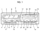
- FIG. 1 1 is a panel or a front wall, which closes a housing 2 of a tachograph rectangular cross section front side.
- a display device 3 are supported as well Keys 4, 5 and 6, 7 out.
- the keys 4 (I) and 7 (II) are used to register the driver and front passenger, the keys 5 and 6 to the release of the respective data cards.
- With 8 of the display device 3 associated window section is designated.
- a spring-mounted cover 9 covers a plug socket; 10 illustrates a warning lamp.
- Slots 11 and 12 serve to input data cards associated with the drivers into read / write units 13 and 14 of the tachograph, wherein the slots 11, 12 are basically formed by respective funnel-shaped depressions 15 and 16.
- a recess 17 is provided, which is covered by a front element 18 of a printing device 19, in such a way that the front element 18 formally, in particular flush, in the front surface of the front wall 1 of the tachograph inserts.
- the printing device 19 comprises a carriage by means of which it can be moved out of the tachograph.
- the carriage may be associated with a bistable detent gear, which, in the event that recording material is to be refilled, by pressing the front member 18, which thus serves as a key, unlocked and locked.
- a plurality of keys 21, 22 and 23, 24 and 25 are mounted in the front element 18, which is provided with a handle bar 20. Together with the keys 4 and 7, these serve to select the most important working time data of the driver and front passenger, the forward and backward scrolling in the respective data records of a selected data type and the triggering of the pressure.
- Denoted by 26 is an outlet port for the printed recording material.
- FIG. 1 the tachograph in question is shown in a state in which the slots 11, 12 accessible and thus data cards are inserted.
- FIG. 2 shows, in contrast, a situation in which in both read / write units 13, 14 data cards 27 and 28 added and the read / write units 13, 14 associated, rotatably mounted Closing elements 29 and 30 are pivoted so that the slots 11, 12 are inaccessible.
- the read / write units 13, 14 are directly associated with one another, namely a printed circuit board 31 occupying essentially the entire housing cross-section transversely to the vertical axis.
- the presentation of electronic components and printed conductors located on the printed circuit board is dispensed with.
- guide cheeks of the read / write units 13, 14 are designated, between which the data cards 27, 28 receiving slides 36 and 37 are slidably mounted.
- the guide cheeks 32, 33 and 34, 35 which are screwed from the opposite side of the circuit board 31 with this, are also designed such that they serve push rods 38 and 39 of the closing elements 29 and 30 actuated drawer gears as storage.
- the push rods 38, 39 are under the action of tension springs 40 and 41 and bear pivotally mounted latch 42 and 43, to which a tension spring 44 engages.
- the latches 42, 43 cooperate with a component of a preassembled gear assembly 45 fastened to the printed circuit board 31, in the sense of unlocking the respective crank mechanism and pivoting the respective closing element 29 , 30 in the open position under the action of one of the tension springs 40 and 41.
- the respective read / write unit 13, 14 is a locking of the respective closing element 29, 30 in the closed position. That is, when entering a data card 27, 28, the respective read / write unit 13, 14 associated push rod 38, 39 is moved to the effective of the relevant bolt 42, 43.
- FIG. 2 shows further that at the, to be unmatched to be mounted, identically shaped carriages 36, 37 projections 46, 47, 48 and 49 are formed, which are bounded by curved surfaces 50, 51, 52 and 53.
- control slide 54 slidably mounted in the transmission assembly 45 curved wedge surfaces 55 and 56.
- two further wedge surfaces 58 and 59 are integrally formed on a mounted on the spool 54 frame 57, each with the release of a data card 27, 28 connected to the slide 36, 37 sliders 60 and 61 come into operative connection with wedge.
- the data cards 27, 28 are automatically transported to the read / write position. That is, when inserting a data card 27, 28 on a carriage 36, 37, a tipping unit is actuated, which causes a mounted on the carriage 36, 37 locking element 62 and 63 is disengaged with provided in the guide walls 33, 35 recesses 64th , 65 and 66, 67. At the same time on the slide 36, 37 located data card 27, 28 stretched by lateral gripping and the respective carriage 36, 37 under the action of a tension spring in the in the FIG. 2 transported read / write position transported.
- a thrust movement of the spool valve 54 after actuation of a key 5 or 6 causes a wedge-geared interaction of the wedge surfaces 55 and 56 with the surfaces 50 and 51 and a displacement of the respective carriage 36, 37 into the input / removal position in which Bar elements 62, 63 initially not yet in the guide cheeks 33, 35 engage.
- the locking of the carriage 36, 37 takes place in the further thrust movement of the spool 54 by the wedge surfaces 58, 59 with the appropriately trained slides 60 and 61 come into operative connection and their thrust movement the respective Kippsprungwerke be operated.
- the spool 54 returns to the in FIG. 2 illustrated central location back.
- FIG. 2 Furthermore, the underside of a supporting board 68 is still visible, which together with another covering board 69 forms a carrier of the gear assembly 45 which supports the control slide 54.
- a conduction band denoted by 70 is provided for the electrical connection of two light barriers 71 and 72 associated with the control slide 54, which in FIG. 3 dash-dotted lines are indicated.
- the attachment of the circuit board 31 in the housing 2 of the tachograph provided through holes is representative designated 73.
- a designated 74 contour represents wall portions of a mounted on the top of the circuit board 31, a plurality of plugs associated plug socket.
- the exploded view of the transmission assembly 45 according to FIG. 3 shows as assembly sequence the essential components of the gear assembly 45, in one of the representation according to FIG. 2 opposite perspective top view. From her it can be seen that on the supporting board 68, a control slide 54 associated with the guide rail 75 and aligned stiffening legs 76 and 77 are formed. With 78 and 79 and 80, on the one hand bars on the other hand, a centering referred to, which are assigned in the covering board 69 stepped openings 81 and 82 and a through hole 83. The assembly of the boards 68 and 69 also serve two locking hooks 84 and 85 which engage the outside of the covering board 69.
- the distance between the boards 68 and 69 and thus the guide gap of the spool 54 results accordingly by the height of the guide rail 75 and by the height of the latching hooks 84, 85 associated with the board 69 but molded in FIG. 3 invisible spacer pin. That is, the faces of the guide rail 75 and spacer pins serve the mutual support of the boards 68 and 69 when locking the latch 78, 79 and the latching hooks 84, 85th
- the spool 54 has a slot 86 which corresponds to the width of the guide list 75.
- 87 designates a toothing formed on the control slide 54; a continuous rib 88 serves to stiffen.
- a tongue 92 is used depending on the thrust direction of the spool 54 the unlocking of one or the other bar 42 and 43 and thus the release of a sliding crank mechanism in the sense of opening the respective closing element 29 and 30. The tongue 92 moves when the boards 68 and 69 are joined, within one in the FIG. 3 invisible slot, which is provided in a formed on the board 69 attachment 93.
- the latter is provided with undercuts 94 and 95, which serve to lock the latch 42, 43.
- Formed in the form of the frame 57 construction of the spool 54 to which the wedge surfaces 58, 59 are formed results between the supporting plate 68 and the spool 54 by the frame 57 surrounds the board 68, a further nesting and thus space utilization ,
- a support function allows and thus a reduction of due to the necessary guide play between the guide rail 75 and the slot 86th the spool 54 existing tilt angle and ultimately achieved an improvement in the switching accuracy.
- the pre-assembly condition according to FIG. 3 shows mounted on the supporting board 68 gear elements, namely a mounted on an axis 96 spur gear 97/98 whose one spur gear 97 after assembly of the spool 54 with the teeth 87 is engaged and the another spur gear 98 meshes with a worm 99 of a worm shaft 100.
- Coaxially with the worm 99 is formed on the worm shaft 100, which is received in one-sided open bearing shells 101 and 102, a spur gear 103 which is engaged with a worm / spur 104/105 pairing on an axis, preferably one with one of the axial fuse serving, that is, provided with a flanged axle 106 is mounted.
- the covering board 69 is only locked to the supporting board 68 to complete the gear assembly 45. It comes on the board 69 also using an axially locking, provided with a flange axis 107 mounted intermediate gear 108 in engagement with the spur gear 105. With 109 is formed on the board 69, the transmission elements encompassing protective wall, which after mounting the gear assembly 45 on the circuit board 31 has only a small distance from the circuit board 31 and thus serves with respect to the transmission elements as pollution protection.
- a spur gear pair 97/98 assigned as axial securing bridge 110 and chambers 111 and 112, which serve the radial securing of the worm shaft 100.
- the spur gear pair 97/98 and the worm / spur gear pair 104/105 are formed as shafts and to store them directly in the boards 68 and 69.
- the read / write units 13, 14 of the selected embodiment require relatively high switching forces, so that the proposed additional axes 96 and 106 represent a more complex but wear-proof solution.
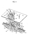
- 113, 114 and 115 are three formed on the board 69 shoulder bolts designated for the attachment of the assembled gear assembly 45 to the circuit board 31 by means of FIG. 4 illustrated screws 116, 117 and 118, which expediently together with in FIG. 4 Not shown washers are used, are provided.
- Pins 119, 120, 121 and 122 which are associated with the sockets 123 and 124 for the light barriers 71, 72, serve to secure the line ends 125 and 126 of the light barriers 71, 72 carrying conduction band 70, for example by hot diving.
- 127 and 128 68 molded on the board guide surfaces are designated, which allow a height narrow and appropriate for the function between the spool 54 and the carriage 36, 37 assignment of the extensions 46, 47 to the carrier 68, 69.
- FIG. 4 finally shows the particularly simple assembly of the gear assembly 45 with the servo motor 129, which is pre-assembled on the circuit board 31.
- immersed on the shaft 130 of the servomotor 129 driving pinion 131 dips into the sleeve-shaped bulge 132 of the protective wall 109 and comes into engagement with the intermediate gear 108.
- the attachment of the servomotor 129 on the circuit board 31 is a holder 133, which in turn under the effect from the circuit board 31 engaging behind bars, one of which in FIG. 4 visible and denoted by 134 is attached to the circuit board 31.
Landscapes
- Physics & Mathematics (AREA)
- General Physics & Mathematics (AREA)
- Time Recorders, Dirve Recorders, Access Control (AREA)
- Recording Measured Values (AREA)
- Coupling Device And Connection With Printed Circuit (AREA)
Claims (13)
- Tachygraphe comportant deux unités de lecture et écriture pour cartes à puce, où les dites unités sont disposées essentiellement dans un même plan, où les cartes à puce affectées au premier et au deuxième conducteur d'un véhicule automobile sont transportées automatiquement, à partir d'une position de lecture et écriture, dans une position d'extraction, caractérisé par le fait que, pour les deux unités de lecture et écriture (13, 14) correspondant, en ce qui concerne leur fixation, directement à une carte à circuits imprimés (31) du tachygraphe, il est prévu un moteur de commande (129) dont le sens de rotation peut être inversé, que le moteur de commande (129) est en prise d'entraînement avec un curseur de commande (54) correspondant aux unités de lecture et écriture (13, 14), qu'il est prévu, sur les deux côtés du curseur de commande (54) en ce qui concerne ses directions de déplacement, des moyens qui déterminent un déplacement des cartes à puce (27, 28) de la position de lecture et écriture dans la position d'extraction, qu'il est prévu un support sur lequel repose le curseur de commande (54) et les organes de transmission (97, 98, 99, 103, 104, 105, 108) reliant fonctionnellement le curseur de commande (54) et le moteur de commande (129).
- Tachygraphe selon la revendication 1, caractérisé par le fait que, sur le curseur de commande (54), sont ménagés des moyens de transmission à clavette (55, 56, 58, 59) pouvant être mis en prise avec les deux unités de lecture et écriture (13, 14).
- Tachygraphe selon la revendication 1, caractérisé par le fait que le support est fixé sur la face de la carte à circuits imprimés (31) sur laquelle se trouvent les unités de lecture et écriture (13, 14).
- Tachygraphe selon la revendication 3, caractérisé par le fait que le moteur de commande (129) est placé sur la face de la carte à circuits imprimés (31) opposée au support et que le pignon d'entraînement (131) qui se trouve sur l'arbre (130) du moteur de commande (129) est en prise avec un organe de transmission (108) monté sur le support.
- Tachygraphe selon la revendication 3, caractérisé par le fait que le support est constitué par deux platines (68, 69) reliées l'une à l'autre, que le curseur de commande (54) est guidé entre les platines (68, 69) et que, sur une platine (69), sont ménagés des boulons à épaulement (113, 114, 115) servant à la fixation dans une position précise du support sur la carte à circuits imprimés (31).
- Tachygraphe selon la revendication 5, caractérisé par le fait que les organes de transmission (97, 98, 99, 103, 104, 105, 108), prévus entre un pignon d'entraînement (131) placé sur l'arbre (130) du moteur de commande (129) et le curseur de commande (54), sont conçus de manière telle qu'ils se trouvent à l'intérieur d'un espace plat formé par des plans extérieurs imaginaires limitant les platines.
- Tachygraphe selon la revendication 5, caractérisé par le fait que les organes de transmission (97, 98, 99, 103, 104, 105, 108) sont montés essentiellement sur une platine (68) et que, sur la platine (68), est formé un organe de guidage (75) correspondant au curseur de commande (54) et agissant perpendiculairement à ses directions de déplacement.
- Tachygraphe selon la revendication 5, caractérisé par le fait que les platines (68, 69) sont reliées l'une à l'autre au moyen de liens d'assemblage et de fixation (78, 79, 80, 84, 85).
- Tachygraphe selon la revendication 3, caractérisé par le fait que les organes de transmission (97, 98, 99, 103, 104, 105, 108) comprennent un ensemble vis sans fin/roue dentée droite (104/105) monté sur un premier axe (106), un couple de roues dentées droites (97/98) monté sur un deuxième axe et un arbre de vis sans fin (100) doté d'une roue dentée droite (103) et d'une vis sans fin (99), la roue dentée droite (103) de l'arbre de vis sans fin (100) étant en prise avec la vis sans fin (104) de l'ensemble vis sans fin / roue dentée droite (104/105) et la vis sans fin (99) de l'arbre de vis sans fin (100) étant en prise avec la roue dentée droite (98) du couple de roues dentées droites (97/ 98).
- Tachygraphe selon la revendication 9, caractérisé par le fait qu'un engrenage (87) est ménagé sur le curseur de commande (54) au moyen duquel le curseur de commande (54) est en prise, dans son état monté sur le support, avec la roue dentée droite (97) du couple de roues dentées droites (97/ 98).
- Tachygraphe selon la revendication 1, caractérisé par le fait que deux barrières lumineuses (71, 72) sont affectées au curseur de commande (54) et que des palettes de commutation (89, 90, 91) intervenant sur les barrières lumineuses (71, 72) sont montées sur le curseur de commande (54).
- Tachygraphe selon la revendication 11, caractérisé par le fait que les palettes de commutation (89, 90, 91) sont montées sur une ligne droite sur le curseur de commande (54) et que l'une (90) des trois barrières lumineuses est plus courte d'une manière insignifiante que l'écart séparant les barrières lumineuses (71, 72).
- Tachygraphe selon la revendication 3, caractérisé par le fait que le moteur de commande (129) est fixé sur le support et qu'il est prévu, sur la carte à circuits imprimés (31), un évidement tel que le moteur de commande (129) traverse la carte à circuits imprimés (31) sans y avoir de contact lorsque le module de transmission (45) est lié à la carte à circuits imprimés (31).
Applications Claiming Priority (2)
| Application Number | Priority Date | Filing Date | Title |
|---|---|---|---|
| DE20015100U | 2000-09-01 | ||
| DE20015100U DE20015100U1 (de) | 2000-09-01 | 2000-09-01 | Fahrtschreiber mit zwei im wesentlichen in einer Ebene angeordneten Lese-/Schreibaggregaten für Datenkarten |
Publications (3)
| Publication Number | Publication Date |
|---|---|
| EP1184667A2 EP1184667A2 (fr) | 2002-03-06 |
| EP1184667A3 EP1184667A3 (fr) | 2004-04-14 |
| EP1184667B1 true EP1184667B1 (fr) | 2010-04-14 |
Family
ID=7945918
Family Applications (1)
| Application Number | Title | Priority Date | Filing Date |
|---|---|---|---|
| EP01120216A Expired - Lifetime EP1184667B1 (fr) | 2000-09-01 | 2001-08-23 | Tachygraphe avec deux unités de lecture/écriture pour cartes de données agencées dans un plan |
Country Status (5)
| Country | Link |
|---|---|
| EP (1) | EP1184667B1 (fr) |
| JP (1) | JP2002117425A (fr) |
| AT (1) | ATE464568T1 (fr) |
| BR (1) | BR0103872A (fr) |
| DE (2) | DE20015100U1 (fr) |
Families Citing this family (10)
| Publication number | Priority date | Publication date | Assignee | Title |
|---|---|---|---|---|
| DE10141177A1 (de) | 2001-08-22 | 2003-03-06 | Siemens Ag | Getriebeanordnung zum wechselweise Betätigen von zwei in einem Fahrtschreiber im wesentlichen in einer Ebene angeordneten Schreib/Leseaggregaten für Chipkarten im Sinne eines Transports jeweils einer Chipkarte in die Entnahmeposition |
| DE10160276A1 (de) * | 2001-12-07 | 2003-06-26 | Siemens Ag | Antriebsanordnung für wenigstens ein in einem Fahrtschreiber angeordnetes Chipkarten-Aufnahmeaggregat zum Verbringen einer Chipkarte in die Entnahmeposition |
| DE10218891B4 (de) * | 2002-04-26 | 2004-03-25 | Siemens Ag | Elektronisches Einbaugerät |
| DE10233442B3 (de) * | 2002-07-23 | 2004-01-08 | Siemens Ag | Überlastschutz |
| DE10233867A1 (de) * | 2002-07-25 | 2004-02-19 | Siemens Ag | Fahrtschreiber mit Chipkarten-Aufnahmeaggregaten |
| DE10246350A1 (de) * | 2002-10-04 | 2004-04-15 | Siemens Ag | Vorrichtung zur Aufnahme und Kontaktierung von zwei kontaktbehafteten Chipkarten |
| SE530354C2 (sv) * | 2005-07-06 | 2008-05-13 | Scania Cv Abp | Arrangemang i ett fordon för inställning av inställbara fordonsfunktioner i enlighet med tidigare inställningar |
| DE102007051400B4 (de) * | 2007-10-25 | 2010-01-21 | Continental Automotive Gmbh | Antriebsanordnung |
| DE102008033926A1 (de) * | 2008-07-18 | 2010-01-21 | Continental Automotive Gmbh | Antriebsanordnung |
| DE102013225672A1 (de) * | 2013-12-11 | 2015-06-11 | Continental Automotive Gmbh | Einbaufahrtschreiber |
Family Cites Families (7)
| Publication number | Priority date | Publication date | Assignee | Title |
|---|---|---|---|---|
| JPH088538Y2 (ja) * | 1990-01-23 | 1996-03-06 | シャープ株式会社 | Icカードのイジェクト装置 |
| DE29604319U1 (de) * | 1996-03-08 | 1996-04-25 | VDO Adolf Schindling AG, 60326 Frankfurt | Führung für einen dem Transport von Datenkarten zwischen einer Eingabe/Entnahmeposition und einer Lese-/Schreibposition dienenden Schlitten |
| DE19732583A1 (de) * | 1997-07-29 | 1999-02-04 | Mannesmann Vdo Ag | Flach bauende Datenkartenaufnahme |
| DE29720521U1 (de) * | 1997-11-19 | 1998-05-14 | Mannesmann VDO AG, 60388 Frankfurt | Fahrtschreiber mit einem flachen, quaderförmigen Einbaugehäuse |
| DE19809619A1 (de) * | 1998-03-06 | 1999-09-09 | Mannesmann Vdo Ag | Vorrichtung zum Transport von Datenkarten |
| DE29916314U1 (de) * | 1999-09-16 | 1999-12-16 | Mannesmann VDO AG, 60388 Frankfurt | Schubgetriebe |
| DE10141177A1 (de) * | 2001-08-22 | 2003-03-06 | Siemens Ag | Getriebeanordnung zum wechselweise Betätigen von zwei in einem Fahrtschreiber im wesentlichen in einer Ebene angeordneten Schreib/Leseaggregaten für Chipkarten im Sinne eines Transports jeweils einer Chipkarte in die Entnahmeposition |
-
2000
- 2000-09-01 DE DE20015100U patent/DE20015100U1/de not_active Expired - Lifetime
-
2001
- 2001-08-23 AT AT01120216T patent/ATE464568T1/de not_active IP Right Cessation
- 2001-08-23 DE DE50115431T patent/DE50115431D1/de not_active Expired - Lifetime
- 2001-08-23 EP EP01120216A patent/EP1184667B1/fr not_active Expired - Lifetime
- 2001-08-31 BR BR0103872-9A patent/BR0103872A/pt not_active IP Right Cessation
- 2001-09-03 JP JP2001266394A patent/JP2002117425A/ja not_active Withdrawn
Also Published As
| Publication number | Publication date |
|---|---|
| ATE464568T1 (de) | 2010-04-15 |
| BR0103872A (pt) | 2002-05-07 |
| DE20015100U1 (de) | 2000-12-21 |
| EP1184667A2 (fr) | 2002-03-06 |
| DE50115431D1 (de) | 2010-05-27 |
| EP1184667A3 (fr) | 2004-04-14 |
| JP2002117425A (ja) | 2002-04-19 |
Similar Documents
| Publication | Publication Date | Title |
|---|---|---|
| EP1184667B1 (fr) | Tachygraphe avec deux unités de lecture/écriture pour cartes de données agencées dans un plan | |
| EP1493129B1 (fr) | Tachygraphe muni d'un boitier parallelepipedique et d'un dispositif d'impression | |
| EP0940765B1 (fr) | Appareil pour le transport de cartes de données | |
| EP1623390B1 (fr) | Imprimante pourvue d'une unite a supports deplacable et verrouillable | |
| DE10153995C1 (de) | Chipkarten-Aufnahmeaggregat | |
| DE68919762T2 (de) | Geldhandhabungsvorrichtung. | |
| EP0364936A2 (fr) | Serrure de porte de véhicule automobile | |
| EP0935220B1 (fr) | Tachygraphe avec un boítier parallélépipédique | |
| EP0342407B1 (fr) | Dispositif pour fermer une fente d'entré/de sortie d'un dispositif d'acquisition de données | |
| DE19635965A1 (de) | Fahrtschreiber mit einer Schublade | |
| EP1419487B1 (fr) | Ensemble d'entrainement pour l'actionnement alterne de deux unites de lecture / ecriture pour cartes a puce, placees essentiellement dans un plan dans un tachygraphe, en vue du transport d'une carte a puce dans la position de prelevement | |
| DE19732583A1 (de) | Flach bauende Datenkartenaufnahme | |
| DE69510517T2 (de) | Universelle Kennzeichenschild-Halterung | |
| DE69704056T2 (de) | Treibstange oder treibstangenschloss, insbesondere mit mehrpunktverriegelung | |
| EP1122121A2 (fr) | Dispositif à conteneur de transport pour le montage dans un véhicule automobile par exemple un dispositif à évidement de chargement | |
| DE69801986T2 (de) | Kompakter drucker | |
| EP1863990B1 (fr) | Mecanisme de commande de bielle | |
| DE3732892C2 (fr) | ||
| EP0547298B1 (fr) | Balance de précision | |
| EP1008964B1 (fr) | Dispositif pour actionner un élément de fermeture d'une ouverture d'entrée/sortie d'une unité de lecture/écriture pour cartes de données | |
| EP1451765B1 (fr) | Systeme d'entrainement pour au moins une unite receptacle de cartes a puces disposee dans un tachygraphe et permettant de placer une carte a puce en position de prelevement | |
| DE4123980C2 (de) | Anzeige- und Bedientafel | |
| EP0698707A1 (fr) | Dispositif de verrouillage central pour chariot porte-outils | |
| DE20312168U1 (de) | Kraftfahrzeugtürverschluss | |
| EP1124205A2 (fr) | Dispositif pour adapter un tachygraphe avec support de disque à diagramme exclusivement coulissant en un tachygraphe avec support de disque à diagramme coulissant et inclinable |
Legal Events
| Date | Code | Title | Description |
|---|---|---|---|
| PUAI | Public reference made under article 153(3) epc to a published international application that has entered the european phase |
Free format text: ORIGINAL CODE: 0009012 |
|
| AK | Designated contracting states |
Kind code of ref document: A2 Designated state(s): AT BE CH CY DE DK ES FI FR GB GR IE IT LI LU MC NL PT SE TR |
|
| AX | Request for extension of the european patent |
Free format text: AL;LT;LV;MK;RO;SI |
|
| PUAL | Search report despatched |
Free format text: ORIGINAL CODE: 0009013 |
|
| AK | Designated contracting states |
Kind code of ref document: A3 Designated state(s): AT BE CH CY DE DK ES FI FR GB GR IE IT LI LU MC NL PT SE TR |
|
| AX | Request for extension of the european patent |
Extension state: AL LT LV MK RO SI |
|
| 17P | Request for examination filed |
Effective date: 20041004 |
|
| AKX | Designation fees paid |
Designated state(s): AT BE CH CY DE DK ES FI FR GB GR IE IT LI LU MC NL PT SE TR |
|
| 17Q | First examination report despatched |
Effective date: 20050217 |
|
| RAP1 | Party data changed (applicant data changed or rights of an application transferred) |
Owner name: CONTINENTAL AUTOMOTIVE GMBH |
|
| GRAP | Despatch of communication of intention to grant a patent |
Free format text: ORIGINAL CODE: EPIDOSNIGR1 |
|
| GRAS | Grant fee paid |
Free format text: ORIGINAL CODE: EPIDOSNIGR3 |
|
| GRAA | (expected) grant |
Free format text: ORIGINAL CODE: 0009210 |
|
| AK | Designated contracting states |
Kind code of ref document: B1 Designated state(s): AT BE CH CY DE DK ES FI FR GB GR IE IT LI LU MC NL PT SE TR |
|
| REG | Reference to a national code |
Ref country code: GB Ref legal event code: FG4D Free format text: NOT ENGLISH |
|
| REG | Reference to a national code |
Ref country code: CH Ref legal event code: EP |
|
| REG | Reference to a national code |
Ref country code: IE Ref legal event code: FG4D Free format text: LANGUAGE OF EP DOCUMENT: GERMAN |
|
| REF | Corresponds to: |
Ref document number: 50115431 Country of ref document: DE Date of ref document: 20100527 Kind code of ref document: P |
|
| REG | Reference to a national code |
Ref country code: SE Ref legal event code: TRGR |
|
| REG | Reference to a national code |
Ref country code: NL Ref legal event code: VDEP Effective date: 20100414 |
|
| PG25 | Lapsed in a contracting state [announced via postgrant information from national office to epo] |
Ref country code: ES Free format text: LAPSE BECAUSE OF FAILURE TO SUBMIT A TRANSLATION OF THE DESCRIPTION OR TO PAY THE FEE WITHIN THE PRESCRIBED TIME-LIMIT Effective date: 20100725 Ref country code: NL Free format text: LAPSE BECAUSE OF FAILURE TO SUBMIT A TRANSLATION OF THE DESCRIPTION OR TO PAY THE FEE WITHIN THE PRESCRIBED TIME-LIMIT Effective date: 20100414 |
|
| REG | Reference to a national code |
Ref country code: IE Ref legal event code: FD4D |
|
| PG25 | Lapsed in a contracting state [announced via postgrant information from national office to epo] |
Ref country code: FI Free format text: LAPSE BECAUSE OF FAILURE TO SUBMIT A TRANSLATION OF THE DESCRIPTION OR TO PAY THE FEE WITHIN THE PRESCRIBED TIME-LIMIT Effective date: 20100414 |
|
| PG25 | Lapsed in a contracting state [announced via postgrant information from national office to epo] |
Ref country code: CY Free format text: LAPSE BECAUSE OF FAILURE TO SUBMIT A TRANSLATION OF THE DESCRIPTION OR TO PAY THE FEE WITHIN THE PRESCRIBED TIME-LIMIT Effective date: 20100414 Ref country code: GR Free format text: LAPSE BECAUSE OF FAILURE TO SUBMIT A TRANSLATION OF THE DESCRIPTION OR TO PAY THE FEE WITHIN THE PRESCRIBED TIME-LIMIT Effective date: 20100715 |
|
| PG25 | Lapsed in a contracting state [announced via postgrant information from national office to epo] |
Ref country code: IE Free format text: LAPSE BECAUSE OF FAILURE TO SUBMIT A TRANSLATION OF THE DESCRIPTION OR TO PAY THE FEE WITHIN THE PRESCRIBED TIME-LIMIT Effective date: 20100414 Ref country code: PT Free format text: LAPSE BECAUSE OF FAILURE TO SUBMIT A TRANSLATION OF THE DESCRIPTION OR TO PAY THE FEE WITHIN THE PRESCRIBED TIME-LIMIT Effective date: 20100816 Ref country code: DK Free format text: LAPSE BECAUSE OF FAILURE TO SUBMIT A TRANSLATION OF THE DESCRIPTION OR TO PAY THE FEE WITHIN THE PRESCRIBED TIME-LIMIT Effective date: 20100414 |
|
| PLBE | No opposition filed within time limit |
Free format text: ORIGINAL CODE: 0009261 |
|
| STAA | Information on the status of an ep patent application or granted ep patent |
Free format text: STATUS: NO OPPOSITION FILED WITHIN TIME LIMIT |
|
| BERE | Be: lapsed |
Owner name: CONTINENTAL AUTOMOTIVE G.M.B.H. Effective date: 20100831 |
|
| 26N | No opposition filed |
Effective date: 20110117 |
|
| PG25 | Lapsed in a contracting state [announced via postgrant information from national office to epo] |
Ref country code: MC Free format text: LAPSE BECAUSE OF NON-PAYMENT OF DUE FEES Effective date: 20100831 Ref country code: IT Free format text: LAPSE BECAUSE OF FAILURE TO SUBMIT A TRANSLATION OF THE DESCRIPTION OR TO PAY THE FEE WITHIN THE PRESCRIBED TIME-LIMIT Effective date: 20100414 |
|
| REG | Reference to a national code |
Ref country code: CH Ref legal event code: PL |
|
| GBPC | Gb: european patent ceased through non-payment of renewal fee |
Effective date: 20100823 |
|
| PG25 | Lapsed in a contracting state [announced via postgrant information from national office to epo] |
Ref country code: CH Free format text: LAPSE BECAUSE OF NON-PAYMENT OF DUE FEES Effective date: 20100831 Ref country code: LI Free format text: LAPSE BECAUSE OF NON-PAYMENT OF DUE FEES Effective date: 20100831 |
|
| PG25 | Lapsed in a contracting state [announced via postgrant information from national office to epo] |
Ref country code: BE Free format text: LAPSE BECAUSE OF NON-PAYMENT OF DUE FEES Effective date: 20100831 |
|
| PG25 | Lapsed in a contracting state [announced via postgrant information from national office to epo] |
Ref country code: GB Free format text: LAPSE BECAUSE OF NON-PAYMENT OF DUE FEES Effective date: 20100823 |
|
| PG25 | Lapsed in a contracting state [announced via postgrant information from national office to epo] |
Ref country code: AT Free format text: LAPSE BECAUSE OF NON-PAYMENT OF DUE FEES Effective date: 20100823 |
|
| PG25 | Lapsed in a contracting state [announced via postgrant information from national office to epo] |
Ref country code: LU Free format text: LAPSE BECAUSE OF NON-PAYMENT OF DUE FEES Effective date: 20100823 |
|
| PG25 | Lapsed in a contracting state [announced via postgrant information from national office to epo] |
Ref country code: TR Free format text: LAPSE BECAUSE OF FAILURE TO SUBMIT A TRANSLATION OF THE DESCRIPTION OR TO PAY THE FEE WITHIN THE PRESCRIBED TIME-LIMIT Effective date: 20100414 |
|
| PGFP | Annual fee paid to national office [announced via postgrant information from national office to epo] |
Ref country code: SE Payment date: 20120821 Year of fee payment: 12 |
|
| PGFP | Annual fee paid to national office [announced via postgrant information from national office to epo] |
Ref country code: FR Payment date: 20120906 Year of fee payment: 12 Ref country code: DE Payment date: 20120831 Year of fee payment: 12 |
|
| REG | Reference to a national code |
Ref country code: SE Ref legal event code: EUG |
|
| PG25 | Lapsed in a contracting state [announced via postgrant information from national office to epo] |
Ref country code: SE Free format text: LAPSE BECAUSE OF NON-PAYMENT OF DUE FEES Effective date: 20130824 Ref country code: DE Free format text: LAPSE BECAUSE OF NON-PAYMENT OF DUE FEES Effective date: 20140301 |
|
| REG | Reference to a national code |
Ref country code: DE Ref legal event code: R119 Ref document number: 50115431 Country of ref document: DE Effective date: 20140301 |
|
| REG | Reference to a national code |
Ref country code: FR Ref legal event code: ST Effective date: 20140430 |
|
| PG25 | Lapsed in a contracting state [announced via postgrant information from national office to epo] |
Ref country code: FR Free format text: LAPSE BECAUSE OF NON-PAYMENT OF DUE FEES Effective date: 20130902 |