EP1184709A1 - Monture de lunettes - Google Patents
Monture de lunettes Download PDFInfo
- Publication number
- EP1184709A1 EP1184709A1 EP00830551A EP00830551A EP1184709A1 EP 1184709 A1 EP1184709 A1 EP 1184709A1 EP 00830551 A EP00830551 A EP 00830551A EP 00830551 A EP00830551 A EP 00830551A EP 1184709 A1 EP1184709 A1 EP 1184709A1
- Authority
- EP
- European Patent Office
- Prior art keywords
- engagement
- support leg
- engagement portion
- spectacle
- lens
- Prior art date
- Legal status (The legal status is an assumption and is not a legal conclusion. Google has not performed a legal analysis and makes no representation as to the accuracy of the status listed.)
- Granted
Links
- 230000008878 coupling Effects 0.000 claims description 5
- 238000010168 coupling process Methods 0.000 claims description 5
- 238000005859 coupling reaction Methods 0.000 claims description 5
- 238000007373 indentation Methods 0.000 claims description 3
- 238000004519 manufacturing process Methods 0.000 description 4
- 239000000463 material Substances 0.000 description 3
- 230000008901 benefit Effects 0.000 description 2
- 238000010276 construction Methods 0.000 description 2
- 239000011521 glass Substances 0.000 description 2
- 238000004064 recycling Methods 0.000 description 2
- 238000004026 adhesive bonding Methods 0.000 description 1
- 230000000694 effects Effects 0.000 description 1
- 238000003780 insertion Methods 0.000 description 1
- 230000037431 insertion Effects 0.000 description 1
- 230000001788 irregular Effects 0.000 description 1
- 239000007769 metal material Substances 0.000 description 1
- 239000002991 molded plastic Substances 0.000 description 1
- 210000000492 nasalseptum Anatomy 0.000 description 1
- 239000004033 plastic Substances 0.000 description 1
- 238000000926 separation method Methods 0.000 description 1
Images


Classifications
-
- G—PHYSICS
- G02—OPTICS
- G02C—SPECTACLES; SUNGLASSES OR GOGGLES INSOFAR AS THEY HAVE THE SAME FEATURES AS SPECTACLES; CONTACT LENSES
- G02C5/00—Constructions of non-optical parts
- G02C5/22—Hinges
- G02C5/2209—Pivot bearings and hinge bolts other than screws
Definitions
- the present invention relates to a spectacle-frame (in the following also “frames” for the sake of brevity) comprising the features set out in the preamble of claim 1.
- frameworks for eyeglasses usually comprise a lens-holding structure and two support legs each of which is rotatably connected with the lens-holding structure through a hinge connection.
- each hinge connection comprises a first hinged portion rigidly in engagement with the lens-holding structure and a second hinged portion rigidly in engagement with the respective support leg.
- Each hinged portion has a through hole which is coincident with the through hole of the other portion so that together they define an articulation housing for engagement of a hinge pin.
- Hinge connections of the above described type projecting from the frames and directly visible thereon, undesirably affect the aesthetic quality of glasses.
- the hinged portions are integrated in one piece into the lens-holding structure and the respective support legs, so that they are as much as possible concealed.
- known frames have problems concerning material recycling.
- separation of the hinge pins, usually made of metal material, from the frames generally made of plastic material is of difficult accomplishment.
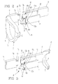
- a framework for eyeglasses in accordance with the present invention has been generally identified by reference numeral 1.
- frames 1 comprise a lens-holding structure 2 to which two support legs 3 are rotatably connected.
- the lens-holding structure 2 has a central rest portion 4, suitable to fit the user's nasal septum, from which two frame-like portions 5 in opposition to each other extend, to define holding seatings 6 for respective lenses (not shown).
- each leg 3 is movable between a closed condition in which it substantially lies in a plane parallel to the lying plane of the glass-holding structure 2 and an open condition in which it lies in a plane substantially perpendicular to the lying plane of the lens-holding structure 2.
- the connecting means 8 comprises, for each support leg 3, at least one hinge pin 9 and at least one articulation seating 10 to be rotatably engaged by the hinge pin 9.
- two hinge pins 9 are preferably provided and for each side support shoulder 7 two articulation seatings 10 are preferably provided.
- Each articulation seating 10 is defined by a first engagement portion 10a formed in frames 1 and a second engagement portion 10b formed in a covering element 11 to be fastened to the frames themselves, preferably within a recess 12 defined by said frames.
- the hinge pins 9 are made unitary with the respective side support shoulder 7 and project externally thereof. More specifically, the hinge pins 9 project upwardly in a substantially vertical direction and downwardly from a coupling lug 7a jutting out in the extension of an end portion 7b of the respective side support shoulder 7.
- the first engagement portions 10a of the respective articulation seatings 10 are formed in respective shoulders 12b defined within the recess 12 provided in the support leg 3.
- shoulders 12b are placed at an end 3a of the respective support leg 3 and lie in a plane substantially normal to the support leg itself.
- the second engagement portions 10b Formed on the covering element 11 and more particularly along a perimetric edge 11a of the latter, are the second engagement portions 10b to be coupled with the respective first engagement portions 10a to define the respective articulation seatings 10.
- the coupling lug 7a of each lea 3 is fitted in a locating cavity 13 formed in the extension of recess 12 between the shoulders 12a carrying the first engagement portions 10a, and terminates at a seating 13a defined in the perimetral edge 11a of the covering element 11 carrying the second engagement portions 10b.
- a second embodiment is therein shown in which, as compared with the embodiment in Fig. 2, positioning of the components of the connecting means 8 carried by legs 3 and the glass-holding structure 2 respectively, are mutually exchanged.
- the hinge pins 9 are unitary with the respective support legs 3 whereas the recess 12 provided with the articulation seatings 10 is defined in the lens-holding structure 2.
- the hinge pins 9 project externally of a coupling protrusion 3c carried by an end portion 3a of the respective support leg 3, whereas the first engagement portions 10a are formed in at least one shoulder 12b defined in the recess 12 provided in the side support shoulder 7.
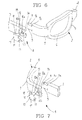
- the connecting means 8 comprises two hinge pins 9 of one piece construction with the respective side support shoulder 7. More specifically, the hinge pins 9 project from opposite inner walls of a respective indentation 7c present in the side support shoulder 7.
- the connecting means 8 further comprises two articulation seatings 10 the first engagement portions 10a of which are formed in a contact surface 14a (not shown in Fig. 4) of an engagement lug 14 carried at the end by the respective support leg 3.
- the contact surface 14a of the engagement lug 14 extends in a plane substantially parallel to leg 3 in the open condition, in a coplanar relationship with, and in the extension of, a bottom wall 12a of the recess 12 adapted to engage the respective covering element 11.
- the second engagement portions 10b are formed in an inner side 11b of the covering element 11 facing the bottom wall 12a of the recess 12.
- the inner side 11b acts in abutment against the bottom wall 12a and the contact surface 14a of the engagement lug 14, thereby defining the articulation seatings 10 through the first and second engagement portions 10a, 10b.
- Fig. 5 Shown in Fig. 5 is a fourth embodiment of the present invention which is very similar to the preceding embodiment, in which however positioning of the components of the connecting means 8 associated with the lens-holding structure 2 and legs 3 respectively, is inverted.
- the hinge pins 9 are associated with the support legs 3 within the respective indentations 7c and the articulation seatings 10 are associated with the side support shoulder 7.
- Fig. 5 Shown in Fig. 5 is a fourth embodiment of the present invention which is very similar to the preceding embodiment, in which however positioning of the components of the connecting means 8 associated with the lens-holding structure 2 and legs 3 respectively, is inverted.
- the hinge pins 9 are associated with the support legs 3 within the respective indentations 7c and the articulation seatings 10 are associated with the side support shoulder 7.
- the articulation seatings 10 are associated with the side support shoulder 7.
- the engagement lug 14 juts out in cantilevered fashion from the respective side support shoulder 7 in the direction of the respective support leg 3, and the contact surface 14a thereof extends without interruption from the bottom wall 12a of recess 12 defined in the side shoulder 7 to receive the covering element 11 carrying the second engagement portions 10b on its inner side 11b facing the bottom wall 12a.
- the hinge pins 9 are associated with the respective side support shoulders 7 and the articulation seatings 10 are formed in the support legs 3.
- the hinge pins 9 are disposed in the same manner as described with reference to the first embodiment shown in Figs. 1 and 2, i.e. projecting in a vertical direction from a coupling lug 7a placed in the end portion 7b of the respective side support shoulder 7.
- the locating recesses 12 are each defined by a through opening of a substantially quadrangular shape essentially extending perpendicular to the extension of the respective support leg 3.
- One or more shoulders 12b project within each recess 12, in a plane substantially parallel to the longitudinal extension of leg 3 in an open condition, and formed at said shoulders 12 are the first engagement portions 10a of the articulation seatings 10.
- the covering element 11 seen in cross section shows a substantially C-shaped profile defined by a lower portion 15, an upper portion 16, and a connecting side portion 17 interposed between the lower portion 15 and upper portion 16. More specifically, both the lower portion 15 and upper portion 16 have an abutment side edge of irregular profile provided with a first step 18 in which the second engagement portion 10b of the articulation seating 10 is formed and with a second substantially flat step 19 extending a greater distance from the connecting side portion 17 than step 18.
- the first step of the lower and upper portions 15, 16 is in abutment against the respective shoulder 12b placed within the recess 12.
- the first and second engagement portions 10a, 10b define the articulation seating 10 for the respective hinge pin 9.
- Fig. 7 Shown in Fig. 7 is a sixth embodiment similar to the fifth one in which positions of the hinge pins 9 and articulation seatings 10 are inverted.
- the present invention solves all problems found in the known art and achieves the intended purposes.
- the frames in accordance with the invention are aesthetically improved due to the presence of the connecting means 8 performing their hinge function between the lens-holding structure 2 and the support legs 3, while surface homogeneity and matching shapes are maintained in said frames 1 seen as a whole.
- the connecting means 8 enables the aesthetically-unpleasant surface holes to be eliminated while completely concealing the hinge pins 9 to sight. Consequently, this connecting means 8 enables a wide design freedom as regards the aesthetic shapes of the frames.
- the concerned frames can be assembled and/or disassembled in an easy and practical manner.
- said leg in each of the proposed embodiments due to the construction conception of the connecting means 8, when the support leg 3 is oriented in the closed condition in the absence of the respective covering element 11, said leg can be freely moved in a longitudinal and/or transverse direction to cause engagement and disengagement of pins 9 with and from the first engagement portions 10a.
- each leg 3 when it is in the open condition can remain steadily linked to the lens-holding structure 2 even in the absence of the respective covering element 11. Due to this condition there is the absence of any sort of stress on the covering elements 11 during normal use of the glasses, for the benefit of a simple and reliable connection of legs 3.
Landscapes
- Physics & Mathematics (AREA)
- Health & Medical Sciences (AREA)
- General Physics & Mathematics (AREA)
- Ophthalmology & Optometry (AREA)
- Optics & Photonics (AREA)
- Eyeglasses (AREA)
- Golf Clubs (AREA)
Priority Applications (3)
| Application Number | Priority Date | Filing Date | Title |
|---|---|---|---|
| EP00830551A EP1184709B1 (fr) | 2000-07-31 | 2000-07-31 | Monture de lunettes |
| AT00830551T ATE256301T1 (de) | 2000-07-31 | 2000-07-31 | Brillenfassung |
| DE60007119T DE60007119D1 (de) | 2000-07-31 | 2000-07-31 | Brillenfassung |
Applications Claiming Priority (1)
| Application Number | Priority Date | Filing Date | Title |
|---|---|---|---|
| EP00830551A EP1184709B1 (fr) | 2000-07-31 | 2000-07-31 | Monture de lunettes |
Publications (3)
| Publication Number | Publication Date |
|---|---|
| EP1184709A1 true EP1184709A1 (fr) | 2002-03-06 |
| EP1184709A8 EP1184709A8 (fr) | 2002-11-20 |
| EP1184709B1 EP1184709B1 (fr) | 2003-12-10 |
Family
ID=8175433
Family Applications (1)
| Application Number | Title | Priority Date | Filing Date |
|---|---|---|---|
| EP00830551A Expired - Lifetime EP1184709B1 (fr) | 2000-07-31 | 2000-07-31 | Monture de lunettes |
Country Status (3)
| Country | Link |
|---|---|
| EP (1) | EP1184709B1 (fr) |
| AT (1) | ATE256301T1 (fr) |
| DE (1) | DE60007119D1 (fr) |
Cited By (3)
| Publication number | Priority date | Publication date | Assignee | Title |
|---|---|---|---|---|
| WO2016079767A1 (fr) * | 2014-11-17 | 2016-05-26 | Soppelsa Sergio | Joint pour l'articulation de lunettes |
| EP3093702A1 (fr) * | 2015-05-15 | 2016-11-16 | Silcon Plastic S.R.L. | Charnière pour articuler une branche à l'avant d'une monture de lunettes |
| US9555102B2 (en) | 2005-05-18 | 2017-01-31 | Stallergenes | Compositions for antigen-specific induction of tolerance |
Citations (6)
| Publication number | Priority date | Publication date | Assignee | Title |
|---|---|---|---|---|
| FR2626682A1 (fr) * | 1989-01-31 | 1989-08-04 | Mugnier Marc | Charnieres de positionnement adaptees aux montures de lunettes |
| WO1990001718A1 (fr) * | 1988-07-29 | 1990-02-22 | Fulvio Brucato | Lunettes |
| US4978209A (en) * | 1988-04-27 | 1990-12-18 | Nikon Corporation | Hinge for spectacle frame |
| EP0495767A1 (fr) * | 1991-01-17 | 1992-07-22 | SILHOUETTE INTERNATIONAL GESELLSCHAFT m.b.H. | Charnière entre branche et monture d'une paire de lunettes |
| WO1994029763A1 (fr) * | 1993-06-07 | 1994-12-22 | Bausch & Lomb Incorporated | Systeme de charniere pour lunettes |
| US5594511A (en) * | 1995-11-13 | 1997-01-14 | Mao Lin Enterprise Co., Ltd. | Eyeglasses with a lens-frame body which can be selectively coupled with either a pair of bows or a head strap |
-
2000
- 2000-07-31 AT AT00830551T patent/ATE256301T1/de not_active IP Right Cessation
- 2000-07-31 DE DE60007119T patent/DE60007119D1/de not_active Expired - Lifetime
- 2000-07-31 EP EP00830551A patent/EP1184709B1/fr not_active Expired - Lifetime
Patent Citations (6)
| Publication number | Priority date | Publication date | Assignee | Title |
|---|---|---|---|---|
| US4978209A (en) * | 1988-04-27 | 1990-12-18 | Nikon Corporation | Hinge for spectacle frame |
| WO1990001718A1 (fr) * | 1988-07-29 | 1990-02-22 | Fulvio Brucato | Lunettes |
| FR2626682A1 (fr) * | 1989-01-31 | 1989-08-04 | Mugnier Marc | Charnieres de positionnement adaptees aux montures de lunettes |
| EP0495767A1 (fr) * | 1991-01-17 | 1992-07-22 | SILHOUETTE INTERNATIONAL GESELLSCHAFT m.b.H. | Charnière entre branche et monture d'une paire de lunettes |
| WO1994029763A1 (fr) * | 1993-06-07 | 1994-12-22 | Bausch & Lomb Incorporated | Systeme de charniere pour lunettes |
| US5594511A (en) * | 1995-11-13 | 1997-01-14 | Mao Lin Enterprise Co., Ltd. | Eyeglasses with a lens-frame body which can be selectively coupled with either a pair of bows or a head strap |
Cited By (4)
| Publication number | Priority date | Publication date | Assignee | Title |
|---|---|---|---|---|
| US9555102B2 (en) | 2005-05-18 | 2017-01-31 | Stallergenes | Compositions for antigen-specific induction of tolerance |
| US10610586B2 (en) | 2005-05-18 | 2020-04-07 | Stallergenes | Compositions for antigen-specific induction of tolerance |
| WO2016079767A1 (fr) * | 2014-11-17 | 2016-05-26 | Soppelsa Sergio | Joint pour l'articulation de lunettes |
| EP3093702A1 (fr) * | 2015-05-15 | 2016-11-16 | Silcon Plastic S.R.L. | Charnière pour articuler une branche à l'avant d'une monture de lunettes |
Also Published As
| Publication number | Publication date |
|---|---|
| ATE256301T1 (de) | 2003-12-15 |
| EP1184709A8 (fr) | 2002-11-20 |
| EP1184709B1 (fr) | 2003-12-10 |
| DE60007119D1 (de) | 2004-01-22 |
Similar Documents
| Publication | Publication Date | Title |
|---|---|---|
| US6575570B2 (en) | Spectacle frame | |
| JP3593044B2 (ja) | 時計ストラップを時計ケーシングに取り付けるための取付装置 | |
| US4780928A (en) | Spring biased hinge for spectacle frames | |
| KR20070010076A (ko) | 안경 프레임 | |
| CA2552424C (fr) | Element de liaison comprenant une enveloppe constituee d'une plaque et d'une plaque arriere | |
| CN101984768A (zh) | 位置稳定的眼镜铰链 | |
| KR20110086212A (ko) | 조립이 용이한 안경테 | |
| EP2000846A1 (fr) | Structure charnière à ressort pour lunettes | |
| CN203178596U (zh) | 眼镜框架 | |
| EP1646906B1 (fr) | Charniere montee en retrait et destinee a rendre elastiques les branches de lunettes | |
| EP1184709B1 (fr) | Monture de lunettes | |
| US20090122255A1 (en) | Spectacles With Interchangeable Temples | |
| US12443050B2 (en) | Snap-fit device for spectacle lens and spectacle frame | |
| KR20130077770A (ko) | 착탈 가능한 다리들을 갖는 안경테 | |
| US7070271B2 (en) | Eyeglasses assembly including main eyeglasses and auxiliary eyeglasses combined with each other via connection bar | |
| KR20090028603A (ko) | 안경용 스프링 힌지 | |
| KR100918482B1 (ko) | 안경 | |
| CN220419729U (zh) | 一种运动眼镜 | |
| CN217213351U (zh) | 一种方便更换的眼镜脚 | |
| KR102636954B1 (ko) | 안경 프레임 | |
| KR200464216Y1 (ko) | 안경테의 렌즈고정림 조정용 경첩 | |
| TWM561809U (zh) | 眼鏡鏡框、鏡片組合結構 | |
| KR102440338B1 (ko) | 손잡이가 결합되는 유리문짝구조 | |
| KR200468580Y1 (ko) | 끼움식 체결구조를 갖는 안경 | |
| CN105572898A (zh) | 眼镜 |
Legal Events
| Date | Code | Title | Description |
|---|---|---|---|
| PUAI | Public reference made under article 153(3) epc to a published international application that has entered the european phase |
Free format text: ORIGINAL CODE: 0009012 |
|
| AK | Designated contracting states |
Kind code of ref document: A1 Designated state(s): AT BE CH CY DE DK ES FI FR GB GR IE IT LI LU MC NL PT SE |
|
| AX | Request for extension of the european patent |
Free format text: AL;LT;LV;MK;RO;SI |
|
| 17P | Request for examination filed |
Effective date: 20020906 |
|
| AKX | Designation fees paid |
Free format text: AT BE CH CY DE DK ES FI FR GB GR IE IT LI LU MC NL PT SE |
|
| GRAH | Despatch of communication of intention to grant a patent |
Free format text: ORIGINAL CODE: EPIDOS IGRA |
|
| RIN1 | Information on inventor provided before grant (corrected) |
Inventor name: MAURI, STEFANO |
|
| GRAS | Grant fee paid |
Free format text: ORIGINAL CODE: EPIDOSNIGR3 |
|
| GRAA | (expected) grant |
Free format text: ORIGINAL CODE: 0009210 |
|
| AK | Designated contracting states |
Kind code of ref document: B1 Designated state(s): AT BE CH CY DE DK ES FI FR GB GR IE IT LI LU MC NL PT SE |
|
| PG25 | Lapsed in a contracting state [announced via postgrant information from national office to epo] |
Ref country code: AT Free format text: LAPSE BECAUSE OF FAILURE TO SUBMIT A TRANSLATION OF THE DESCRIPTION OR TO PAY THE FEE WITHIN THE PRESCRIBED TIME-LIMIT Effective date: 20031210 Ref country code: BE Free format text: LAPSE BECAUSE OF FAILURE TO SUBMIT A TRANSLATION OF THE DESCRIPTION OR TO PAY THE FEE WITHIN THE PRESCRIBED TIME-LIMIT Effective date: 20031210 Ref country code: CY Free format text: LAPSE BECAUSE OF FAILURE TO SUBMIT A TRANSLATION OF THE DESCRIPTION OR TO PAY THE FEE WITHIN THE PRESCRIBED TIME-LIMIT Effective date: 20031210 Ref country code: NL Free format text: LAPSE BECAUSE OF FAILURE TO SUBMIT A TRANSLATION OF THE DESCRIPTION OR TO PAY THE FEE WITHIN THE PRESCRIBED TIME-LIMIT Effective date: 20031210 Ref country code: CH Free format text: LAPSE BECAUSE OF FAILURE TO SUBMIT A TRANSLATION OF THE DESCRIPTION OR TO PAY THE FEE WITHIN THE PRESCRIBED TIME-LIMIT Effective date: 20031210 Ref country code: FR Free format text: LAPSE BECAUSE OF FAILURE TO SUBMIT A TRANSLATION OF THE DESCRIPTION OR TO PAY THE FEE WITHIN THE PRESCRIBED TIME-LIMIT Effective date: 20031210 Ref country code: LI Free format text: LAPSE BECAUSE OF FAILURE TO SUBMIT A TRANSLATION OF THE DESCRIPTION OR TO PAY THE FEE WITHIN THE PRESCRIBED TIME-LIMIT Effective date: 20031210 Ref country code: FI Free format text: LAPSE BECAUSE OF FAILURE TO SUBMIT A TRANSLATION OF THE DESCRIPTION OR TO PAY THE FEE WITHIN THE PRESCRIBED TIME-LIMIT Effective date: 20031210 |
|
| REG | Reference to a national code |
Ref country code: GB Ref legal event code: FG4D |
|
| REG | Reference to a national code |
Ref country code: CH Ref legal event code: EP |
|
| REG | Reference to a national code |
Ref country code: IE Ref legal event code: FG4D |
|
| REF | Corresponds to: |
Ref document number: 60007119 Country of ref document: DE Date of ref document: 20040122 Kind code of ref document: P |
|
| PG25 | Lapsed in a contracting state [announced via postgrant information from national office to epo] |
Ref country code: GR Free format text: LAPSE BECAUSE OF FAILURE TO SUBMIT A TRANSLATION OF THE DESCRIPTION OR TO PAY THE FEE WITHIN THE PRESCRIBED TIME-LIMIT Effective date: 20040310 Ref country code: DK Free format text: LAPSE BECAUSE OF FAILURE TO SUBMIT A TRANSLATION OF THE DESCRIPTION OR TO PAY THE FEE WITHIN THE PRESCRIBED TIME-LIMIT Effective date: 20040310 Ref country code: SE Free format text: LAPSE BECAUSE OF FAILURE TO SUBMIT A TRANSLATION OF THE DESCRIPTION OR TO PAY THE FEE WITHIN THE PRESCRIBED TIME-LIMIT Effective date: 20040310 |
|
| PG25 | Lapsed in a contracting state [announced via postgrant information from national office to epo] |
Ref country code: DE Free format text: LAPSE BECAUSE OF FAILURE TO SUBMIT A TRANSLATION OF THE DESCRIPTION OR TO PAY THE FEE WITHIN THE PRESCRIBED TIME-LIMIT Effective date: 20040311 |
|
| PG25 | Lapsed in a contracting state [announced via postgrant information from national office to epo] |
Ref country code: ES Free format text: LAPSE BECAUSE OF FAILURE TO SUBMIT A TRANSLATION OF THE DESCRIPTION OR TO PAY THE FEE WITHIN THE PRESCRIBED TIME-LIMIT Effective date: 20040321 |
|
| NLV1 | Nl: lapsed or annulled due to failure to fulfill the requirements of art. 29p and 29m of the patents act | ||
| REG | Reference to a national code |
Ref country code: CH Ref legal event code: PL |
|
| PG25 | Lapsed in a contracting state [announced via postgrant information from national office to epo] |
Ref country code: MC Free format text: LAPSE BECAUSE OF NON-PAYMENT OF DUE FEES Effective date: 20040731 Ref country code: GB Free format text: LAPSE BECAUSE OF NON-PAYMENT OF DUE FEES Effective date: 20040731 Ref country code: LU Free format text: LAPSE BECAUSE OF NON-PAYMENT OF DUE FEES Effective date: 20040731 |
|
| PG25 | Lapsed in a contracting state [announced via postgrant information from national office to epo] |
Ref country code: IE Free format text: LAPSE BECAUSE OF NON-PAYMENT OF DUE FEES Effective date: 20040802 |
|
| PLBE | No opposition filed within time limit |
Free format text: ORIGINAL CODE: 0009261 |
|
| STAA | Information on the status of an ep patent application or granted ep patent |
Free format text: STATUS: NO OPPOSITION FILED WITHIN TIME LIMIT |
|
| 26N | No opposition filed |
Effective date: 20040913 |
|
| EN | Fr: translation not filed | ||
| GBPC | Gb: european patent ceased through non-payment of renewal fee |
Effective date: 20040731 |
|
| REG | Reference to a national code |
Ref country code: IE Ref legal event code: MM4A |
|
| PG25 | Lapsed in a contracting state [announced via postgrant information from national office to epo] |
Ref country code: PT Free format text: LAPSE BECAUSE OF NON-PAYMENT OF DUE FEES Effective date: 20040510 |
|
| PGFP | Annual fee paid to national office [announced via postgrant information from national office to epo] |
Ref country code: IT Payment date: 20100727 Year of fee payment: 11 |
|
| PG25 | Lapsed in a contracting state [announced via postgrant information from national office to epo] |
Ref country code: IT Free format text: LAPSE BECAUSE OF NON-PAYMENT OF DUE FEES Effective date: 20110731 |