EP1184733A2 - Système de commande à distance, méthode et support de stockage pour appareil de formation d'images - Google Patents
Système de commande à distance, méthode et support de stockage pour appareil de formation d'images Download PDFInfo
- Publication number
- EP1184733A2 EP1184733A2 EP01402268A EP01402268A EP1184733A2 EP 1184733 A2 EP1184733 A2 EP 1184733A2 EP 01402268 A EP01402268 A EP 01402268A EP 01402268 A EP01402268 A EP 01402268A EP 1184733 A2 EP1184733 A2 EP 1184733A2
- Authority
- EP
- European Patent Office
- Prior art keywords
- information
- apparatuses
- control system
- received
- image forming
- Prior art date
- Legal status (The legal status is an assumption and is not a legal conclusion. Google has not performed a legal analysis and makes no representation as to the accuracy of the status listed.)
- Withdrawn
Links
Images








Classifications
-
- H—ELECTRICITY
- H04—ELECTRIC COMMUNICATION TECHNIQUE
- H04N—PICTORIAL COMMUNICATION, e.g. TELEVISION
- H04N1/00—Scanning, transmission or reproduction of documents or the like, e.g. facsimile transmission; Details thereof
- H04N1/00127—Connection or combination of a still picture apparatus with another apparatus, e.g. for storage, processing or transmission of still picture signals or of information associated with a still picture
- H04N1/00204—Connection or combination of a still picture apparatus with another apparatus, e.g. for storage, processing or transmission of still picture signals or of information associated with a still picture with a digital computer or a digital computer system, e.g. an internet server
-
- G—PHYSICS
- G03—PHOTOGRAPHY; CINEMATOGRAPHY; ANALOGOUS TECHNIQUES USING WAVES OTHER THAN OPTICAL WAVES; ELECTROGRAPHY; HOLOGRAPHY
- G03G—ELECTROGRAPHY; ELECTROPHOTOGRAPHY; MAGNETOGRAPHY
- G03G15/00—Apparatus for electrographic processes using a charge pattern
- G03G15/50—Machine control of apparatus for electrographic processes using a charge pattern, e.g. regulating differents parts of the machine, multimode copiers, microprocessor control
- G03G15/5075—Remote control machines, e.g. by a host
- G03G15/5079—Remote control machines, e.g. by a host for maintenance
-
- G—PHYSICS
- G03—PHOTOGRAPHY; CINEMATOGRAPHY; ANALOGOUS TECHNIQUES USING WAVES OTHER THAN OPTICAL WAVES; ELECTROGRAPHY; HOLOGRAPHY
- G03G—ELECTROGRAPHY; ELECTROPHOTOGRAPHY; MAGNETOGRAPHY
- G03G2215/00—Apparatus for electrophotographic processes
- G03G2215/00025—Machine control, e.g. regulating different parts of the machine
- G03G2215/00109—Remote control of apparatus, e.g. by a host
- G03G2215/00113—Plurality of apparatus configured in groups each with its own host
Definitions
- This patent specification relates generally to a system and method for remote control, and more specifically to a system, method and computer accessible storage medium for implementing remote control of image forming apparatuses, which are connected to a central control system, based on information transferred by way of telecommunication network.
- a remote control method has been known for image forming apparatuses, in which a central control system located at a service center is transmissively connected to these apparatuses of various customers by way of telecommunication network (such as the public switched telephone network) to transmit information and to perform the control based on the information.
- telecommunication network such as the public switched telephone network
- Previous control systems therefore, have the construction such that a central control system is connected to a plurality of image forming apparatus via telecommunication network, a variety pieces of information are relayed through the network, and the control is performed by the central control system based on the information.
- the fault is reported to the central control system regarding the kind of fault, name and model of the apparatus, and time of fault occurrence, among others.
- the fault report is then displayed on a display screen of computer terminal (client computer).
- an operator at the terminal finds the details of the apparatus and customer such as the location of installation, time of fault occurrence (year, month, day, hour and minute), nature of the fault, method of fault recovery and so on.
- the operator determines from the content of report whether a service engineer is to be dispatched, to subsequently make several arrangements such as, for example, issuing a request to the client depot (service center), if necessary, for dispatching a service engineer (or sales engineer) in charge from the depot.
- a center operator finds from the content of the display the details of the customer, from which the information is sent, regarding to the time (year, month, day, hour and minute) of the arrival of the pre-maintenance, or supplementing the expendable supplies such as paper sheets, toner and others.
- the operator determines whether a service engineer is to be dispatched, and subsequently makes several arrangements such as, for example, issuing a request to the client depot, if necessary, for dispatching from the depot an engineer in charge and for the delivery of the supplies.
- a service engineer is already dispatched to a first customer to deal with a report previously received.
- another information is then received by the center operator regarding to the request of service dispatch to a second customer who is closely located (e.g., at the same floor in the same building) to the first customer, the service engineer may not be able to respond to the second customer simply because the engineer is already working for the first customer.
- a remote control system for controlling a plurality of apparatuses including at least an image forming apparatus including a central control system (or center system) comprising a computer unit for receiving information from the plurality of apparatuses via respective telecommunication networks interconnected thereto, and for remotely controlling the plurality of apparatuses based on the information received via the respective telecommunication networks; and including information collection means for collecting, based on the kind of the information presently received, related information from all of the plurality of apparatuses included in the same groups other than that, from which the information is originally transmitted, in the case where the information is received by the center system from any one of the plurality of apparatuses to be remotely controlled, which are divided into a predetermined number of groups.
- the remote control system may also include information processing means for processing the information either received from the plurality of apparatuses or collected by the information collection means; information transmission means for transmissively connecting to respective computer systems or terminal units provided by a plurality of service centers (service depots) so as to control the plurality of image forming apparatuses in a manner divided into a predetermined number of groups, and subsequently transmitting the information processed by the information processing means; and means for setting in advance the kind of the information, for which the collection process by the information collection means is allowed.
- information processing means for processing the information either received from the plurality of apparatuses or collected by the information collection means
- information transmission means for transmissively connecting to respective computer systems or terminal units provided by a plurality of service centers (service depots) so as to control the plurality of image forming apparatuses in a manner divided into a predetermined number of groups, and subsequently transmitting the information processed by the information processing means
- means for setting in advance the kind of the information, for which the collection process by the information collection means is allowed are examples of
- the information collected from all of the plurality of apparatuses by the information collection means is related to the items of pre-maintenance, or of expendable supplies and material.
- the remote control system for controlling a plurality of apparatuses including at least an image forming apparatus includes a central control system comprising a computer unit for receiving information from the plurality of apparatuses via respective telecommunication networks interconnected thereto, and for remotely controlling the plurality of apparatuses based on the information received via the respective telecommunication networks; information accumulation means for accumulating information, in the case where the information is received by the central control system from any one of the plurality of apparatuses, which are divided into a predetermined number of groups; and information retrieval means for retrieving, based on the kind of the information presently received, related information from all of the plurality of apparatuses included in the same groups other than that, from which the information is originally transmitted, in the case where the information is received by the central control system from any one of the plurality of apparatuses.
- the remote control system may also include information processing means for processing the information which is either received from the plurality of apparatuses or retrieved by the information retrieval means; information transmission means for transmissively connecting to respective computer systems provided by a plurality of service centers so as to control the plurality of image forming apparatuses in a manner divided into a predetermined number of groups, and subsequently transmitting the information processed by the information processing means; means for setting in advance the kind of the information, for which the retrieval process by the information retrieval means is allowed, and group setting means for setting a group in advance by dividing the plurality of image forming apparatuses into a predetermined number of groups.
- the remote control system includes at least a central control system comprising a computer unit for receiving information from the plurality of apparatuses via respective telecommunication networks interconnected to the plurality of apparatuses, and for remotely controlling the plurality of apparatuses based on the information received via the respective telecommunication networks; information collection means for collecting, based on the kind of the information presently received, related information from all of the plurality of apparatuses included in the same groups other than that, from which the information is originally transmitted, in the case where the information is received by the central control system from any one of the plurality of apparatuses to be remotely controlled, which are divided into a predetermined number of groups; first information processing means for processing the information received from any one of the plurality of apparatuses; first information transmission means for transmissively connecting to respective terminal units provided by a plurality of service centers so as to control the plurality of image forming apparatuses in a manner divided into a predetermined number of groups, and subsequently transmitting the information processed by the information processing means; information accumulation means for a central control system compris
- a method for controlling a plurality of apparatuses including at least an image forming apparatus including at least the step of receiving information relayed to a central control system from the plurality of apparatuses via respective telecommunication networks; controlling remotely the plurality of apparatuses based on the thus received information; collecting information related to pre-maintenance and to expendable supplies and material from all of the plurality of apparatuses included in the same groups other than that, from which the information is originally transmitted, in the case where the information related to pre-maintenance and to expendable supplies and material is received from any one of the plurality of apparatuses; processing either received or collected information by information processing means; transmissively connecting to respective terminal units provided by a plurality of service centers so as to control the plurality of image forming apparatuses in a manner divided into a predetermined number of groups; and transmitting the information processed by the information processing means.
- the method may further include the steps of performing alteration and addition onto the information processed by the information processing means; and outputting the information processed by the information processing means through the means of a display device, a paper sheet or audible voice, and transmitting the information processed by the information processing means, in case where a request for acquiring the processed information is received from any one of terminal units.
- a central control system included in the remote control system for controlling a plurality of apparatuses including at least an image forming apparatus, based on information received by the central control system via respective telecommunication networks interconnected to the plurality of apparatuses, including at least information collection means for collecting, based on the kind of the information presently received, related information from all of the plurality of apparatuses included in the same groups other than that, from which the information is originally transmitted, in the case where the information related to pre-maintenance and to expendable supplies and material is received by the central control system from any one of the plurality of apparatuses to be remotely controlled, which are divided into a predetermined number of groups; first information processing means for processing the information received from any one of the plurality of apparatuses; first information transmission means for transmissively connecting to respective terminal units provided by a plurality of service centers so as to control the plurality of image forming apparatuses in a manner divided into a predetermined number of groups, and subsequently transmitting the information processed by
- a computer accessible recording medium tangibly embodying a program of instructions executable by a central control system included in a remote control system to perform method steps for controlling a plurality of apparatuses including at least an image forming apparatus, based on information received by the central control system via respective telecommunication networks interconnected to the plurality of apparatuses, in which the steps includes at least collecting, based on the kind of the information presently received, related information from all of the plurality of apparatuses included in the same groups other than that, from which the information is originally transmitted, in the case where the information related to pre-maintenance and to expendable supplies and material is received by the central control system from any one of the plurality of apparatuses to be remotely controlled, which are divided into a predetermined number of groups; processing the information received from any one of the plurality of apparatuses; transmissively connecting to respective terminal units provided by a plurality of service centers so as to control the plurality of image forming apparatuses in a manner divided into a predetermined number of groups
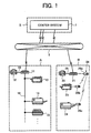
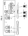
- FIG. 1 is a schematic diagram illustrating the construction of a remote control system for the image forming apparatuses (hereinafter referred to as image forming apparatus control system), and FIG. 2 is a schematic diagram illustrating the configuration of a center system (or central control system ) included in the image forming apparatus control system, and service locations, according to one embodiment disclosed herein.
- image forming apparatus control system a remote control system for the image forming apparatuses
- FIG. 2 is a schematic diagram illustrating the configuration of a center system (or central control system ) included in the image forming apparatus control system, and service locations, according to one embodiment disclosed herein.
- the image forming apparatus control system includes at least the center system 1 installed at a service center S, a plurality of electronic apparatuses provided on the side of various customers (users) A, B, ... , and a plurality of terminal units 7a, 7b, ... 7n (or computer systems including the terminal units) located at respective service centers (or service depots).
- exchange systems for the customers A, B, ... are herein abbreviated in the drawing.
- the center system 1 is thus provided with a plurality of client computers (hereinafter referred to as clients) 2a, 2b, ... 2n, and a server 3, which are interconnected via the network system 4 such as LAN.
- the clients 2a, 2b, ... 2n are, in turn, connected respectively either to communication adapters 11, 12, ... of respective customers A, B, ... via the public switched telephone network 5 (or other communication network), or to the terminal units 7a, 7b, ... 7n located respectively at service centers via the net work system 6 (or other communication network) such as LAN.
- the terminal units 7a, 7b, ... 7n are utilized to control the plurality of image forming apparatuses, which are provided by a plurality of customers (users) A, B, ... , and are divided into the predetermined number of groups.
- a communication adapter 11 to be utilized for connecting electronic apparatuses to the center system 1 in the service center S via the public switched telephone network 5 (or other communication network), a plurality of image forming apparatuses such as a facsimile apparatus (FAX) 12, copying machine 13, printer 14 and printing machine 15.
- FAX facsimile apparatus
- image forming apparatuses and communication adapter 11 are further interconnected with a wire exclusive interface (I/F) 16.
- I/F wire exclusive interface
- Another communication adapter 21 to be utilized for connecting electronic apparatuses to the center system 1 in the service center S via the public switched telephone network 5 (or other communication network), a plurality of image forming apparatuses such as a facsimile apparatus (FAX) 22, copying machine 23 and printer 24.
- FAX facsimile apparatus
- image forming apparatuses and communication adapter 21 are further interconnected with a wireless exclusive interface (I/F) 26.
- I/F wireless exclusive interface
- the wireless exclusive I/F 26 includes at least plural wireless communication apparatuses 26a, 26b and 26c which are connected to the communication adapter 21, copying machine 23 and printer 24, respectively.
- a network such as LAN may alternatively be used in place of either wire exclusive I/F 16 or wireless exclusive IF 26, which will be detailed later on.
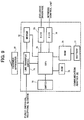
- FIG. 3 is a block diagram illustrating the configuration of the clients 2a, 2b, ... 2n, and the server 3, of FIG. 2.
- the client 2a includes at least CPU 31, real time clock circuit 32, read only memory (ROM) 33, random access memory (RAM) 34, communication control units 35a, 35b, ... , external memory control unit 36, display control unit 37, keyboard I/F circuit unit 38, network I/F unit 39, hard disk unit 40, CRT display 41 and keyboard 42.
- ROM read only memory
- RAM random access memory
- the CPU 31 operates as a central processing unit to take overall control of the client 2a by means of control programs.
- the real time clock circuit 32 generates time information which is read by the CPU 31 to be used in the control, and the ROM 33 is a read only memory unit for storing various fixed data to be utilized by the CPU 31.
- the RAM 34 is a rewritable memory unit to be utilized by the CPU 31 as a working memory for data processing.
- the communication control units 35a, 35b each take control of communicating with various external units via the public switched telephone network 5, and the external memory control unit 36 takes interface control of the hard disk unit (HDD) 40.
- HDD hard disk unit
- the display control unit 37 takes interface control of the CRT display 41 (or other display unit such as LCD display, as well).
- the keyboard I/F circuit unit 38 takes interface control of the keyboard 42.
- the network I/F unit 39 takes interface control of other clients such as including 2b, for example, and the server 3.
- the server 3 includes at least CPU 51, real time clock circuit 52, ROM 53, RAM 54, external memory control unit 55, display control unit 56, keyboard I/F circuit unit 57, network I/F unit 58, HDD 59, CRT display 60 and keyboard 61.
- the CPU 51 operates as a central processing unit to take overall control of the server 3 by means of control programs stored in the ROM 53.
- the real time clock circuit 52 generates time information which is read by the CPU 51 to be used in the control of the server 3.
- the ROM 53 is a read only memory unit for storing various fixed data to be utilized by the CPU 51
- the RAM 54 is a rewritable memory unit to be utilized for data processing by the CPU 51 as a working memory for data processing.
- the external memory control unit 55 takes interface control of the HDD 59.
- the HDD 59 stores several data including at least the customer data base (DB) 59a and the temporal reception DB 59b, shown in FIG. 2.
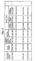
- the customer DB 59a is adapted to store various pieces of information (customer information) utilized to specify the customers, consisting of the name and model of the apparatus; ID, name, address, area code, building name and floor number of the customer; name and phone number of the person in charge; name, model, unit number and connection ID of the communication adapter; name, address, engineer personnel (or service engineer in charge) of respective service depots.
- customer information utilized to specify the customers, consisting of the name and model of the apparatus; ID, name, address, area code, building name and floor number of the customer; name and phone number of the person in charge; name, model, unit number and connection ID of the communication adapter; name, address, engineer personnel (or service engineer in charge) of respective service depots.
- the temporal reception DB 59b is adapted to store temporal information which is received from the customers A, B,... as shown in FIG. 6, consisting of time of receiving the information (year, month, day, hour and minute); name, model and manufacturing number of the apparatus; reception ID code; detailed data, information regarding the propriety for the maintenance operation and so on.
- the display control unit 56 takes interface control of the CRT display 60 (or other display unit such as LCD display, as well).
- the keyboard I/F circuit unit 57 takes interface control of the keyboard 61.
- the network I/F unit 58 takes interface control of other clients 2a, 2b, ... 2n connected to the network 4.
- FIG. 7 is a block diagram illustrating the construction of the communication adapter 11 of FIG. 1. Since the configuration of the communication adapter 21 is similar to that of the adapter 11, the graphic representation and description thereof are herein abbreviated.
- a variety of data sent through the public switched telephone network 5 is first input to a line transfer switch 71. If the data transmission from the network 5 is addressed to the FAX 12 connected to the communication adapter 11, the line transfer switch 71 is adapted to connect the network 5 to the FAX 12. In contrast, if the data transmission is sent from the center system 1, the switch 71 is adapted to connect the network 5 to the modem 72.
- the communication adapter 11 is adapted to communicate with the image forming apparatus such as copying machine 13 by means of the communication interface (Serial I/O or S I/O) 73 using an RS-485 type transceiver, for example.
- the communication interface Serial I/O or S I/O
- RS-485 type transceiver for example.
- the RAM 76 is in use for tentatively storing a variety of data and supplied with a backup battery 77 connected thereto.
- the switch 78 is adapted to selectively switch among various modes of the processing operation. Further, the communication adapter 11 is designed to perform poling actions consistently and periodically onto respective image forming apparatuses connected thereto, which is performed according to the order of device address.
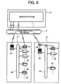
- FIG. 8 is a schematic diagram illustrating the construction of a further remote control system for the image forming apparatuses according to another embodiment disclosed herein. It is noted that like reference numerals in FIG. 8 designate identical or corresponding parts of FIG. 1.
- the image forming apparatus control system includes at least the center system 1 installed at a service center S, a plurality of electronic apparatuses provided on the side of various customers A, B, ... , a plurality of terminal units 7a, 7b, ... 7n (or computer systems including the terminal units) located at respective service centers, in a similar manner as shown in FIG. 2.
- exchange systems for the customers A, B, ... are herein abbreviated in the present drawing.
- the center system 1 is thus provided with a plurality of client computers (hereinafter referred to as clients) 2a, 2b, ... 2n, and a server 3, which are interconnected via the net work system 4 such as LAN.
- clients client computers
- server 3 which are interconnected via the net work system 4 such as LAN.
- the clients 2a, 2b, ... 2n are, in turn, connected respectively either to network (NW) control unit 87 or communication adapters 96, ... via the public switched telephone network 5 (or other communication network), or to the terminal units 7a, 7b, ... 7n located respectively at service centers via the net work system 6 (or other communication network) such as LAN.
- NW network
- the clients 2a, 2b, ... 2n are, in turn, connected respectively either to network (NW) control unit 87 or communication adapters 96, ... via the public switched telephone network 5 (or other communication network), or to the terminal units 7a, 7b, ... 7n located respectively at service centers via the net work system 6 (or other communication network) such as LAN.
- NW network
- FIG. 8 On the side of customer A (FIG. 8), there provided are several image forming apparatus as the electronic apparatuses, including a FAX 81, printers 82 and 83, copying machine 84 and printing machine 85. These apparatuses are then interconnected via the net work system 86 such as LAN. In addition, the NW control unit 87 is adapted to properly interconnect the network 86 and the public switched telephone network 5 (or other communication network).
- the electronic apparatuses On the side of customer B, there provided as the electronic apparatuses are several image forming apparatus, including a FAX 91, printers 92 and copying machine 93. These apparatuses are then connected via the net work system 94 such as LAN.
- the NW control unit 95 is adapted to properly interconnect the network 94 and the public switched telephone network 5 (or other communication network).
- the FAX 91 with the network 94 is made directly connectable to the public switched telephone network 5, the communication adapters 96 is provided between the NW control unit 95 and the public switched telephone network 5; and the above noted FAX 91, that is directly connectable to the public switched telephone network 5, is connected to the communication adapters 96.
- the configuration of the clients 2a, 2b, ... 2n, and the server 3 is broadly similar to that previously shown in FIG. 3, with the exception that the content, which is stored in the customer DB 59a in the server 3, is slightly different from that shown in FIGS. 4 and 5.
- IP address network address
- FIG. 9 is a block diagram illustrating the construction of the communication adapter 96 of FIG. 8. Like reference numerals in FIG. 9 designate identical or corresponding part in FIG. 7, and the description on the identical portions is herein abbreviated.
- the communication adapter 96 is adapted to communicate with the NW control unit 95 by means of the communication interface (S I/O) 73 using an RS-485 type transceiver, for example.
- the center system 1 of FIGS. 1 and 8 is then able to implement various modes of the present disclosure. Namely, systems and process steps disclosed in the present description may be implemented by executing a plurality of programs stored in various storage media.
- storage media may be prepared for storing a variety of programs in the center system 1 to execute the above described steps for processing information and deciding conditions.
- the storage media may include computer accessible storage media such as an external floppy disk and optical disk, among others. These storage media may subsequently be installed into an internal HDD unit, non-volatile RAM or RAM, to thereby be able execute necessary steps to embody the various modes of the present disclosure according to various programs.
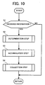
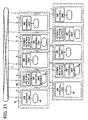
- FIGS. 10 through 16 each contain flow charts illustrating information process flows for respective embodiments, in which the number of each step is headed by 'S' for abbreviation.
- FIG. 10 includes a flow chart illustrating an information process flow for the center system 1 including a plurality of clients 2a, 2b, ... 2n.
- the clients 2a, 2b, ... 2n in the center system 1 each initiate regularly and periodically the process steps shown in the figure as follows.
- step S1 a program checks if any information is received.
- a plurality of customers A, B, ... each provided with a plurality of image forming apparatuses, which are divided into a predetermined a predetermined number of groups so as to facilitate their identification.
- step 1 therefore, an inquiry is made regarding whether information is received from any one of the plurality of image forming apparatuses (FIG. 1 or 8), which are provided by a plurality of customers A, B, ..., and divided into the predetermined number of groups. If the information is received already from any of the image forming apparatuses, the process proceeds to Step 2, where a program is executed to identify the kind of the received information.
- step 3 the thus received information is processed in step 3 so as to be accumulated into a temporal reception DB 59b (memory) included in the server 3.
- a temporal reception DB 59b (memory) included in the server 3.
- Step 3 the process proceeds to Step 4, where a program is executed, in response to the kind of the received information identified as above, to collect the corresponding information from other image forming apparatuses included in the same groups other than that, from which the information is originally received.
- the client 2a included in the center system 1 receives, from one of image forming apparatuses within its interconnection, information regarding the arrival of the pre-maintenance date (or pre-maintenance date information), several steps are executed so as to identify the kind of the thus received information, to store (or accumulate) the information into a temporal reception DB 59b in the server 3, and then to collect, in response to the kind of the received information, the information related to the arrival of the pre-maintenance date (pre-maintenance date information) from other image forming apparatuses included in the same groups other than that, from which the information is originally transmitted.
- image forming apparatuses to be presently subjected can be identified, by retrieving the customer DB 59a, as those having the name and number apparatus such as ⁇ XX ⁇ 1 ⁇ , ⁇ XX ⁇ 5 ⁇ and ⁇ XX ⁇ m ⁇ .
- the customer DB 59a As those having the name and number apparatus such as ⁇ XX ⁇ 1 ⁇ , ⁇ XX ⁇ 5 ⁇ and ⁇ XX ⁇ m ⁇ .
- responded information transmitted back from each of the presently subjected apparatuses can thus be collected.
- the center system 1 instructs to collect responded information from all of the image forming apparatuses included in the same groups within its interconnection other than that, from which the information is originally transmitted.
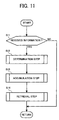
- FIG. 11 includes a flow chart illustrating a further information process flow for the center system 1 including a plurality of clients 2a, 2b, ... and 2n.
- the clients 2a, 2b, ... 2n in the center system 1 each initiate regularly and periodically the process steps shown in the figure as follows.
- step S11 an inquiry is made regarding whether information is received from any one of the plurality of image forming apparatuses, which are provided by a plurality of customers A, B, ..., and which are divided into a predetermined number of groups.
- Step 12 a program is executed to identify the kind of the received information.
- step 13 the thus received information is processed in step 13 so as to be accumulated into the temporal reception DB 59b included in the server 3.
- step 13 the process proceeds to step 14, where a program is executed, in response to the kind of the received information identified above, to retrieve from the temporal reception DB 59b the corresponding information which is received from other image forming apparatuses included in the same groups other than that, from which the information is originally received.
- image forming apparatuses to be presently subjected can be identified, by retrieving the customer DB 59a, as those having the name and number of the apparatus such as ⁇ XX ⁇ 1 ⁇ , ⁇ XX ⁇ 5 ⁇ and ⁇ XX ⁇ m ⁇ (in response to the pre-maintenance information received, in the present case).
- an inquiry is subsequently made whether there exists, among the apparatuses ⁇ XX ⁇ 1 ⁇ , ⁇ XX ⁇ 5 ⁇ and ⁇ XX ⁇ m ⁇ , for which no processing action has been taken based on the pre-maintenance information (i.e., the information notifying the arrival of the pre-maintenance date).
- the pre-maintenance information i.e., the information notifying the arrival of the pre-maintenance date.
- the center system 1 instructs to accumulate the received information into the temporal reception DB 59b, and to retrieve from the temporal reception DB 59b, in response to the kind of the received information obtained previously, the related information already received from all of the other image forming apparatuses included in the same groups other than that, from which the information is originally transmitted.
- a service engineer can therefore deal with incoming information by effective remedial measures in efficient and economical manner when the information is received.
- the center system 1 does not instruct to collect additional information in the present embodiment, thereby incurring no additional cost of communication. As a result, the cost of the service operation is further reduced.
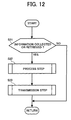
- FIG. 12 includes a flow chart illustrating an information process flow for the center system 1 including a plurality of clients 2a, 2b, ... 2n.
- Step 22 a program is executed to proceed as follows.
- Step 22 the process proceeds to Step 23, where a program is executed for the center system to be transmissively connected to the respective terminal units 7a, 7b, ... 7n (or computer systems), and to transmit the above noted several processed information thereto.
- terminal units 7a, 7b, ... 7n are, in turn, already provided by the plurality of service centers to control the plurality of image forming apparatuses, which are provided by a plurality of customers A, B, ..., in a manner divided into a predetermined number of groups.
- information regarding the arrival of the pre-maintenance date is either received from an image forming apparatus, or from other image forming apparatuses included in the same groups other than that, from which the information is originally received; or obtained through retrieval process from the temporal reception DB 59b, the process proceeds as follows.
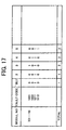
- the record for the currently subjected apparatus is processed for the period ranging from the previous maintenance to the time when the current information is either received, or retrieved from the temporal reception DB 59b.
- This is exemplified in FIG. 17, as the kind of the fault reported, and the number of monthly occurrence of the fault for this subjected apparatus.
- the thus processed information or record is subsequently file transferred to a terminal (or computer system) which is attended by a personnel in charge of the service center, or by a sales engineer (or service engineer) for the area.
- the terminal On the receipt of the processed information from the center system 1, the terminal instructs for a display unit to display the content of the processed information so as to be readily observed by a terminal operator.
- the clients 2a, 2b, ... 2n in the center system 1 instructs to further carry out the processing the information either received or retrieved, subsequently be transmissively connected to the respective terminal units 7a, 7b, ... 7n (or computer systems) which are provided by the plurality of service centers so as to control the plurality of image forming apparatuses, and to transmit the above noted several processed information thereto.
- connection may alternatively be established directly to a terminal (e.g., handheld computer unit) owned by service engineer, to thereby be able to transfer directly the processed information or data.
- a terminal e.g., handheld computer unit
- the kind of information i.e., the information received from the plurality of image forming apparatuses which are provided by the plurality of customers A, B, ... , and divided into a predetermined number of groups
- the kind of information i.e., the information received from the plurality of image forming apparatuses which are provided by the plurality of customers A, B, ... , and divided into a predetermined number of groups
- this setting operation may be carried out regarding to the thus items such as pre-maintenance, expendable supplies and material, fault, alarm (which is sent when a specified value is exceeded, although not the fault), and the combination thereof.
- a program is executed to collect the information related to the set items from other image forming apparatuses included in the same groups other than that, from which the information is originally received, and also to retrieve the previously received and stored (or accumulated) information from the temporal reception DB 59b.
- the kind of information to be either received or retrieved is set in advance in the present embodiment. Namely, when information is received by the respective clients 2a, 2b, ..., 2n in the center system 1 from any one of the plurality of image forming apparatuses, which are divided into a predetermined number of groups, the center system 1 instructs to collect the information related to the set items from other image forming apparatuses included in the same groups other than that, from which the information is originally received, and also to retrieve the previously received and stored (or accumulated) information from the temporal reception DB 59b.
- the plurality of image forming apparatuses which are provided by the plurality of customers A, B, ... are divided in advance into a predetermined number of groups.
- the groups may respectively be assigned to the clients 2a, 2b, ... 2n by input operations with the keyboard 42, for example.
- this assignment can be carried out in any one of the following manners (1) through (5):
- the clients 2a, 2b, ... 2n in the center system 1 are each capable of diving in advance the plurality of image forming apparatuses which are provided by the plurality of customers A, B, ... , into a predetermined number of groups in the present embodiment, it becomes feasible to eliminate undue man-hour and cost for the data reprocessing, thereby facilitating a wider use of the present system in various applications.
- a change in the service unit i.e., one of the above noted division in the group
- one item e.g., service location
- another e.g., customer' s name or apparatus name
- one fixed group of the customer data may necessitates a thorough re-processing of the data, which may require an additional and appreciable period of time.
- FIG. 13 includes a flow chart illustrating an information process flow for the center system 1 including a plurality of clients 2a, 2b, ... 2n.
- FIG. 13 The additional steps in FIG. 13 are also initiated regularly and periodically in similar manner to those of FIGS. 10 and 11, in which an inquiry is made first in Step 31 whether any information is present regarding to the information either collected in the process steps shown in FIG. 10, or retrieved in the process steps shown in FIG. 11.
- Step 32 a program is executed to proceed as follows.
- Step 32 the process proceeds to Step 33, where steps are taken on the above processed information to make any alteration or addition, if necessary.
- the necessary items may be exemplified by those such as early action required, propriety for the maintenance operation, customer requirements, technical information and others.
- Step 34 a program is executed for the center system to be transmissively connected to the respective terminal units 7a, 7b, ... 7n (or computer systems), and to transmit the above noted several processed information thereto.
- terminal units 7a, 7b, ... 7n are, in turn, already provided by the plurality of service centers so as to control the plurality of image forming apparatuses, which are provided by a plurality of customers A, B, ..., in a manner divided into a predetermined number of groups.
- the clients 2a, 2b, ... 2n in the center system 1 transmit the thus processed information primarily in a fixed format, there may give rise the failure in appropriate responding action. This is caused when an important or most urgent point of the information such as 'occurrence of the unit failure' in the customer comments is necessary, the fixed format is not sufficient to report the important point, thereby necessitating additional means such as telephone or facsimile, while failing in quick responding action on the other.
- the clients 2a, 2b, ... 2n in the center system 1 transmits the thus processed information again in a fixed format
- the alteration or revision of the transmitted information in that format may necessitate a considerable work load of an operator at the swerve depot, thereby causing additional work load and undue period of time.
- the clients 2a, 2b, ... 2n in the center system 1 are each capable of providing the alteration and addition onto the processed information in the present embodiment, the utility of the processed information with the system is further increased by the addition of a requisite and important comment, for example. In addition, more effective measures can be taken in the event where any alteration or addition becomes necessary with the present system.
- Process steps according to a seventh embodiment are described, in which the clients 2a, 2b, ... 2n in the center system 1 carries out similar process steps as those of the previous embodiments 3 through 6, including transmitting the processed information.
- the destination of information transmission is set in advance by input operations with the keyboard 42, for example.
- the clients 2a, 2b, ... 2n in the center system 1 is adapted to operate as follows.
- Step 32 information either received or retrieved is first processed in Step 32. After completing Step 32, necessary alteration or addition is made in Step 33, and several terminal units among 7a, 7b, ... 7n (or computer systems), which are set in advance as the destination of information transmission, are transmissively connected for the transmission, and the above processed information is subsequently transmitted thereto in Step 34.
- 7a, 7b, ... 7n or computer systems
- the clients 2a, 2b, ... 2n in the center system 1 are each capable of setting in advance several terminal units among 7a, 7b, ... 7n (or computer systems), as the destination of information transmission, the processed information can be transferred automatically to respective destinations, to thereby be able reducing the work load of center operators.
- the clients 2a, 2b, ... 2n in the center system 1 are each capable of providing the alteration and addition onto the processed information, and transmitting the thus prepared information to several terminal units set in advance as the destination of information transmission, to thereby be able facilitate various activities for retaining and also improving the qualities of the terminal apparatuses.
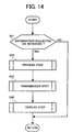
- FIG. 14 includes a flow chart illustrating an information process flow for the center system 1 including a plurality of clients 2a, 2b, ... 2n.
- FIG. 12 The additional steps in FIG. 12 are also initiated regularly and periodically in similar manner to those of FIGS. 10 and 11, in which an inquiry is made first in Step 41 whether any information is present regarding to the information either collected in the process steps shown in FIG. 10, or retrieved in the process steps shown in FIG. 11.
- Step 42 a program is executed to proceed as follows.
- Step 43 where the clients 2a, 2b, ... 2n in the center system 1 instructs to be transmissively connected to the respective terminal units 7a, 7b, ... 7n (or computer systems) which are provided by the plurality of service centers so as to control the plurality of image forming apparatuses.
- the clients 2a, 2b, ... 2n may instruct to be transmissively connected to several terminal units among 7a, 7b, ... 7n, as the destination of information transmission which is set in advance.
- the process subsequently proceeds for the processed information to be transmitted to the destination, and to be displayed on CRT display unit 41.
- the clients 2a, 2b, ... 2n in the center system 1 are each capable of displaying the processed information on CRT display unit 41, to thereby facilitating for the center operator to confirm the content of the information with ease, there becomes feasible with the present system are a re-transmission of the information to the terminals following possible alteration or addition of the processed information and a transmission of the information via facsimile and some other means (or backup processing) during interruption of terminal units or the fault of the network.
- the clients 2a, 2b, ... 2n in the center system 1 may respectively provide alteration or addition onto the processed inforaamtion, and subsequently transmit the thus prepared information to the terminals and display on CRT display unit 41.
- the information following the processing, or alteration or addition may be output audibly using a voice response (output) unit through a speaker unit, or printed-out (forming images on a sheet) through a printer unit.
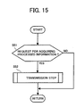
- FIG. 15 includes a flow chart illustrating an information process flow for the center system 1 including a plurality of clients 2a, 2b, ... 2n.
- Step 51 The additional steps in FIG. 15 are also initiated regularly and periodically, in which an inquiry is made first in Step 51 whether any request for acquiring the processed information is received from any one of the terminal units 7a, 7b, ... 7n (or computer systems), that are provided by the plurality of service centers.
- a program is executed to send the processed information to the terminal, from which the request is received.
- the terminal units 7a, 7b, ... 7n (or computer systems), which are provided by the plurality of service centers via the network 6, can each issue request to acquire the information which is processed and provided with alteration or addition, at need, by the clients 2a, 2b, ... 2n in the center system 1 (which is altogether referred to hereinafter as 'processed information').
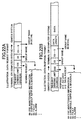
- FIG. 22A The data format for requesting the acquisition of the processed information (or data request format) is illustrated in FIG. 22A, in which several items for dividing into group are shown such as customer's name, service location and dealer' s name. Further detailed division of the respective items are specified by customer' s ID number for the customer' s name, or office or department; a code for service location and dealer' s name; a unit code for the apparatuses, respectively.
- the clients 2a, 2b, ... 2n in the center system 1 are each adapted to retrieve the temporal reception DB 59b shown in FIG. 6 based on predetermined conditions.
- the range for the retrieval may be set as related data, for example, over a predetermined period of time.
- the clients 2a, 2b, ... 2n in the center system 1 are each capable of transmitting processed information to the sending terminal, when any request for acquiring the processed information is received from any one of the terminal units 7a, 7b, ... 7n, it becomes feasible with the present system to carry out recovery operations by just sending a re-issuing request to the center system 1, even in the case of data loss or breakdown due to possible fault of network system 6, or failure or operational error at the side of terminal units 7a, 7b, ... 7n.
- the occurrence of customer' s claims can therefore be alleviated.
- FIG. 16 includes a flow chart illustrating an information process flow for the center system 1 including a plurality of clients 2a, 2b, ... 2n.
- the clients 2a, 2b, ... 2n in the center system 1 each initiate regularly and periodically the process steps shown in the figure as follows.
- step S61 an inquiry is made regarding whether information is received from any one of the plurality of image forming apparatuses (FIG. 1 or 8), which are provided by a plurality of customers A, B, ..., and divided into the predetermined number of groups. If the information is received already from any of the image forming apparatuses, the process proceeds to Step 62, where a program is executed to identify the kind of the received information.
- step 63 the thus received information is processed in step 63 so as to be accumulated into a temporal reception DB 59b included in the server 3.
- Step 3 the process proceeds to Step 64, where a program is executed either to set a flag for information collection or retrieval, or not to set any such a flag, in response to the kind of the received information identified above.
- the program is executed such that either one of the information collection/ processing (i.e., collecting information and related processing of the information, which will be described later on) and information retrieval/ processing (i.e., retrieving information and related processing of the information, which will be described later on) be allowed, or neither be allowed.
- the information collection/ processing i.e., collecting information and related processing of the information, which will be described later on
- information retrieval/ processing i.e., retrieving information and related processing of the information, which will be described later on
- the flag for information collection is set (i.e., information collection/ processing is allowed).
- the flag for information retrieval is set (i.e., information retrieval/ processing is allowed).
- Step 64 After completing Step 64, the process proceeds to Step 65, where a program is executed to check whether an information collection flag is set.
- Step 67 a program is executed to check whether an information retrieval flag is set.
- the process proceeds to follow any one of the group of steps shown in FIGS. 12 through 14, in which, in the case where collection/ processing steps are previously carried out, the information received from the plurality of image forming apparatuses which are provided by the plurality of customers A, B, ... , and divided into a predetermined number of groups, and the information collected through the steps of FIG. 16, are both processed.
- the information received from the plurality of image forming apparatuses which are provided by the plurality of customers A, B, ... , and divided into a predetermined number of groups, and the information retrieved through the steps of FIG. 16, are both processed.
- the clients 2a, 2b, ... 2n in the center system 1 are each capable of instructing to either one of the information collection/ processing step and retrieval/ processing step be allowed, or neither of the steps be allowed.
- storage media may be prepared for storing a variety of programs for the clients 2a, 2b, ... 2n in the center system 1 to execute the above described steps for processing information and deciding conditions.
- the storage media may include computer accessible storage media such as a floppy disk and optical disk, among others.
- These storage media may be installed into a floppy disk unit and CD-ROM reader, respectively, in a conventional general-purpose processor, to thereby for the programs stored therein be read out and installed further into an internal hard disk unit. As a result, the capability of the image forming apparatus control system can be properly carried out.
- the present disclosure also includes a computer-based product which may be hosted on a storage medium and include instructions which can be used to program a processor to perform a process in accordance with the present disclosure.
- the storage medium can include, but is not limited to, any type of disk including floppy disks, optical disks, CD-ROMS, magneto-optical disks, ROMs, RAMs, EPROMs, EEPROMS, flash memory, magnetic or optical cards, or any type of media suitable for storing electronic instructions.
- control system and method incorporating the storage medium may also be adopted to other apparatus and center system such as a keycard control apparatus for managing the number of copy duplication for respective groups, gas meter, electric power meter, vending machine, among others.
Landscapes
- Engineering & Computer Science (AREA)
- Computing Systems (AREA)
- General Engineering & Computer Science (AREA)
- Multimedia (AREA)
- Signal Processing (AREA)
- Microelectronics & Electronic Packaging (AREA)
- Physics & Mathematics (AREA)
- General Physics & Mathematics (AREA)
- Control Or Security For Electrophotography (AREA)
- Facsimiles In General (AREA)
- Computer And Data Communications (AREA)
- Selective Calling Equipment (AREA)
- Telephonic Communication Services (AREA)
- Accessory Devices And Overall Control Thereof (AREA)
Applications Claiming Priority (2)
| Application Number | Priority Date | Filing Date | Title |
|---|---|---|---|
| JP2000260143A JP4025000B2 (ja) | 2000-08-30 | 2000-08-30 | 遠隔管理システムおよび遠隔管理方法とそれに使用する中央管理装置並びに記録媒体 |
| JP2000260143 | 2000-08-30 |
Publications (2)
| Publication Number | Publication Date |
|---|---|
| EP1184733A2 true EP1184733A2 (fr) | 2002-03-06 |
| EP1184733A3 EP1184733A3 (fr) | 2005-01-26 |
Family
ID=18748197
Family Applications (1)
| Application Number | Title | Priority Date | Filing Date |
|---|---|---|---|
| EP01402268A Withdrawn EP1184733A3 (fr) | 2000-08-30 | 2001-08-30 | Système de commande à distance, méthode et support de stockage pour appareil de formation d'images |
Country Status (3)
| Country | Link |
|---|---|
| US (1) | US20020026541A1 (fr) |
| EP (1) | EP1184733A3 (fr) |
| JP (1) | JP4025000B2 (fr) |
Cited By (3)
| Publication number | Priority date | Publication date | Assignee | Title |
|---|---|---|---|---|
| EP1357700A3 (fr) * | 2002-04-22 | 2004-01-02 | Ricoh Company, Ltd. | Dispositif de traitement d'images dans un environnement de gestion de réseau |
| EP2216182A1 (fr) * | 2009-02-05 | 2010-08-11 | Xerox Corporation | Contrôle à distance d'alimentation continue pour mouvement de papier à faible vitesse |
| CN110658752A (zh) * | 2019-09-16 | 2020-01-07 | 北京中能云联科技有限公司 | 一种应用于远程云监控的数据采集系统 |
Families Citing this family (9)
| Publication number | Priority date | Publication date | Assignee | Title |
|---|---|---|---|---|
| US7643894B2 (en) * | 2002-05-09 | 2010-01-05 | Netstreams Llc | Audio network distribution system |
| US9137035B2 (en) * | 2002-05-09 | 2015-09-15 | Netstreams Llc | Legacy converter and controller for an audio video distribution system |
| US7200844B2 (en) * | 2002-08-08 | 2007-04-03 | Hewlett-Packard Development Company, Lp. | User installation of imaging device control system |
| JP2004295866A (ja) * | 2003-03-11 | 2004-10-21 | Ricoh Co Ltd | 電子装置とその遠隔管理システムおよびログ管理方法並びにプログラム |
| US20060184588A1 (en) * | 2005-02-15 | 2006-08-17 | Canon Kabushiki Kaisha | Information processing apparatus, method, and program for executing retrieval processing |
| KR101362374B1 (ko) * | 2007-03-07 | 2014-02-12 | 삼성전자주식회사 | 화상형성장치의 드라이버 시스템 및 그 제어방법 |
| US20100303046A1 (en) * | 2009-05-27 | 2010-12-02 | Netstreams, Llc | Wireless video and audio network distribution system |
| JP6155974B2 (ja) * | 2013-08-27 | 2017-07-05 | 株式会社リコー | 管理装置、管理方法及びプログラム |
| JP7047456B2 (ja) * | 2018-02-26 | 2022-04-05 | 富士フイルムビジネスイノベーション株式会社 | 画像処理装置及びプログラム |
Family Cites Families (12)
| Publication number | Priority date | Publication date | Assignee | Title |
|---|---|---|---|---|
| JP2644554B2 (ja) * | 1988-11-15 | 1997-08-25 | 株式会社日立製作所 | 情報処理システム |
| JP3660363B2 (ja) * | 1992-05-28 | 2005-06-15 | 株式会社リコー | 画像形成装置管理システムとその画像形成装置 |
| JP3442174B2 (ja) * | 1995-01-19 | 2003-09-02 | 株式会社リコー | 画像形成装置サービスシステム |
| JP3604504B2 (ja) * | 1996-05-31 | 2004-12-22 | 株式会社リコー | 管理装置と画像形成装置サービスシステム並びに故障発生予測方法 |
| JPH10322396A (ja) * | 1997-05-21 | 1998-12-04 | Mitsubishi Electric Corp | 発信情報中継サーバ及び発信情報中継方法並びにそのシステム |
| US6415392B1 (en) * | 1997-12-08 | 2002-07-02 | Ricoh Company, Ltd. | Remote diagnosis system and method |
| JP3065053B2 (ja) * | 1998-01-06 | 2000-07-12 | セイコーエプソン株式会社 | 機器監視システム、ローカル監視装置、統合監視装置、機器監視方法、及び、プログラムを格納したコンピュータ可読媒体 |
| US6310692B1 (en) * | 1998-05-15 | 2001-10-30 | Kuji Xerox Co. Ltd. | Dynamic, preventive, centralized printer resource management system and method |
| US6343320B1 (en) * | 1998-06-09 | 2002-01-29 | Compaq Information Technologies Group, L.P. | Automatic state consolidation for network participating devices |
| JP3970430B2 (ja) * | 1998-07-10 | 2007-09-05 | 株式会社リコー | 画像形成装置サービスシステム |
| US6446192B1 (en) * | 1999-06-04 | 2002-09-03 | Embrace Networks, Inc. | Remote monitoring and control of equipment over computer networks using a single web interfacing chip |
| US6748437B1 (en) * | 2000-01-10 | 2004-06-08 | Sun Microsystems, Inc. | Method for creating forwarding lists for cluster networking |
-
2000
- 2000-08-30 JP JP2000260143A patent/JP4025000B2/ja not_active Expired - Fee Related
-
2001
- 2001-08-30 EP EP01402268A patent/EP1184733A3/fr not_active Withdrawn
- 2001-08-30 US US09/941,680 patent/US20020026541A1/en not_active Abandoned
Cited By (5)
| Publication number | Priority date | Publication date | Assignee | Title |
|---|---|---|---|---|
| EP1357700A3 (fr) * | 2002-04-22 | 2004-01-02 | Ricoh Company, Ltd. | Dispositif de traitement d'images dans un environnement de gestion de réseau |
| US7542158B2 (en) | 2002-04-22 | 2009-06-02 | Ricoh Company, Ltd. | Image forming apparatus |
| EP2216182A1 (fr) * | 2009-02-05 | 2010-08-11 | Xerox Corporation | Contrôle à distance d'alimentation continue pour mouvement de papier à faible vitesse |
| US7976006B2 (en) | 2009-02-05 | 2011-07-12 | Xerox Corporation | Continuous feed remote control for slow speed paper motion |
| CN110658752A (zh) * | 2019-09-16 | 2020-01-07 | 北京中能云联科技有限公司 | 一种应用于远程云监控的数据采集系统 |
Also Published As
| Publication number | Publication date |
|---|---|
| US20020026541A1 (en) | 2002-02-28 |
| JP4025000B2 (ja) | 2007-12-19 |
| JP2002073437A (ja) | 2002-03-12 |
| EP1184733A3 (fr) | 2005-01-26 |
Similar Documents
| Publication | Publication Date | Title |
|---|---|---|
| US7385928B2 (en) | Image forming device management system and method | |
| US7355730B2 (en) | Office machine that can be remote-maintenanced via a computer network and a management or/and support or/and report or/and information system comprising a plurality of office machines | |
| KR940001080B1 (ko) | 사진복사 감시 시스템 | |
| CN1874283B (zh) | 集中监视系统及其控制方法 | |
| JP3725718B2 (ja) | 画像形成装置管理システム | |
| US20020183978A1 (en) | Remote maintenance and diagnosis of office or domestic appliances | |
| HK1003337B (en) | Photocopy monitoring system and method for monitoring copiers | |
| US20090094091A1 (en) | Service call data selection and delivery method and system | |
| EP1184733A2 (fr) | Système de commande à distance, méthode et support de stockage pour appareil de formation d'images | |
| US7899950B2 (en) | System and method for remote communication with a multifunctional device | |
| US7249171B2 (en) | Service control system and computer program | |
| US7382480B2 (en) | Supervising system for image forming apparatus and method thereof | |
| JP4043177B2 (ja) | 画像形成装置管理システム及び管理方法 | |
| US20040098400A1 (en) | Method and system for service management or/and for service support or/and for the generation of service reports | |
| US6956934B2 (en) | Management system and method, and data processing apparatus | |
| JP3157147B2 (ja) | 遠隔管理装置 | |
| JP4545258B2 (ja) | 遠隔集中管理システム | |
| JP2001175128A (ja) | 画像形成装置管理システム | |
| JP3538105B2 (ja) | 営業情報配信システム | |
| JP2000181302A (ja) | 画像形成装置管理システム | |
| JP3641159B2 (ja) | 遠隔集中管理装置、遠隔集中管理装置システムおよび遠隔集中管理方法 | |
| JP2000013518A (ja) | 画像形成装置管理システム | |
| JP2001042966A (ja) | 周辺機器の保守管理方法及び保守管理装置 | |
| JP2001024830A (ja) | 画像形成装置管理システム | |
| JP2002268857A (ja) | 画像形成装置管理システム |
Legal Events
| Date | Code | Title | Description |
|---|---|---|---|
| PUAI | Public reference made under article 153(3) epc to a published international application that has entered the european phase |
Free format text: ORIGINAL CODE: 0009012 |
|
| AK | Designated contracting states |
Kind code of ref document: A2 Designated state(s): AT BE CH CY DE DK ES FI FR GB GR IE IT LI LU MC NL PT SE TR |
|
| AX | Request for extension of the european patent |
Free format text: AL;LT;LV;MK;RO;SI |
|
| PUAL | Search report despatched |
Free format text: ORIGINAL CODE: 0009013 |
|
| AK | Designated contracting states |
Kind code of ref document: A3 Designated state(s): AT BE CH CY DE DK ES FI FR GB GR IE IT LI LU MC NL PT SE TR |
|
| AX | Request for extension of the european patent |
Extension state: AL LT LV MK RO SI |
|
| STAA | Information on the status of an ep patent application or granted ep patent |
Free format text: STATUS: THE APPLICATION IS DEEMED TO BE WITHDRAWN |
|
| 17P | Request for examination filed |
Effective date: 20050704 |
|
| 18D | Application deemed to be withdrawn |
Effective date: 20050301 |