EP1185376B1 - Abgabevorrichtung für medien - Google Patents
Abgabevorrichtung für medien Download PDFInfo
- Publication number
- EP1185376B1 EP1185376B1 EP00927352A EP00927352A EP1185376B1 EP 1185376 B1 EP1185376 B1 EP 1185376B1 EP 00927352 A EP00927352 A EP 00927352A EP 00927352 A EP00927352 A EP 00927352A EP 1185376 B1 EP1185376 B1 EP 1185376B1
- Authority
- EP
- European Patent Office
- Prior art keywords
- piece
- syringe
- outer body
- actuated
- dose
- Prior art date
- Legal status (The legal status is an assumption and is not a legal conclusion. Google has not performed a legal analysis and makes no representation as to the accuracy of the status listed.)
- Expired - Lifetime
Links
Images


Classifications
-
- B—PERFORMING OPERATIONS; TRANSPORTING
- B05—SPRAYING OR ATOMISING IN GENERAL; APPLYING FLUENT MATERIALS TO SURFACES, IN GENERAL
- B05B—SPRAYING APPARATUS; ATOMISING APPARATUS; NOZZLES
- B05B11/00—Single-unit hand-held apparatus in which flow of contents is produced by the muscular force of the operator at the moment of use
- B05B11/01—Single-unit hand-held apparatus in which flow of contents is produced by the muscular force of the operator at the moment of use characterised by the means producing the flow
- B05B11/02—Membranes or pistons acting on the contents inside the container, e.g. follower pistons
-
- B—PERFORMING OPERATIONS; TRANSPORTING
- B05—SPRAYING OR ATOMISING IN GENERAL; APPLYING FLUENT MATERIALS TO SURFACES, IN GENERAL
- B05B—SPRAYING APPARATUS; ATOMISING APPARATUS; NOZZLES
- B05B1/00—Nozzles, spray heads or other outlets, with or without auxiliary devices such as valves, heating means
- B05B1/34—Nozzles, spray heads or other outlets, with or without auxiliary devices such as valves, heating means designed to influence the nature of flow of the liquid or other fluent material, e.g. to produce swirl
- B05B1/3405—Nozzles, spray heads or other outlets, with or without auxiliary devices such as valves, heating means designed to influence the nature of flow of the liquid or other fluent material, e.g. to produce swirl to produce swirl
- B05B1/341—Nozzles, spray heads or other outlets, with or without auxiliary devices such as valves, heating means designed to influence the nature of flow of the liquid or other fluent material, e.g. to produce swirl to produce swirl before discharging the liquid or other fluent material, e.g. in a swirl chamber upstream the spray outlet
- B05B1/3421—Nozzles, spray heads or other outlets, with or without auxiliary devices such as valves, heating means designed to influence the nature of flow of the liquid or other fluent material, e.g. to produce swirl to produce swirl before discharging the liquid or other fluent material, e.g. in a swirl chamber upstream the spray outlet with channels emerging substantially tangentially in the swirl chamber
- B05B1/3431—Nozzles, spray heads or other outlets, with or without auxiliary devices such as valves, heating means designed to influence the nature of flow of the liquid or other fluent material, e.g. to produce swirl to produce swirl before discharging the liquid or other fluent material, e.g. in a swirl chamber upstream the spray outlet with channels emerging substantially tangentially in the swirl chamber the channels being formed at the interface of cooperating elements, e.g. by means of grooves
- B05B1/3436—Nozzles, spray heads or other outlets, with or without auxiliary devices such as valves, heating means designed to influence the nature of flow of the liquid or other fluent material, e.g. to produce swirl to produce swirl before discharging the liquid or other fluent material, e.g. in a swirl chamber upstream the spray outlet with channels emerging substantially tangentially in the swirl chamber the channels being formed at the interface of cooperating elements, e.g. by means of grooves the interface being a plane perpendicular to the outlet axis
-
- B—PERFORMING OPERATIONS; TRANSPORTING
- B05—SPRAYING OR ATOMISING IN GENERAL; APPLYING FLUENT MATERIALS TO SURFACES, IN GENERAL
- B05B—SPRAYING APPARATUS; ATOMISING APPARATUS; NOZZLES
- B05B1/00—Nozzles, spray heads or other outlets, with or without auxiliary devices such as valves, heating means
- B05B1/34—Nozzles, spray heads or other outlets, with or without auxiliary devices such as valves, heating means designed to influence the nature of flow of the liquid or other fluent material, e.g. to produce swirl
- B05B1/3405—Nozzles, spray heads or other outlets, with or without auxiliary devices such as valves, heating means designed to influence the nature of flow of the liquid or other fluent material, e.g. to produce swirl to produce swirl
- B05B1/341—Nozzles, spray heads or other outlets, with or without auxiliary devices such as valves, heating means designed to influence the nature of flow of the liquid or other fluent material, e.g. to produce swirl to produce swirl before discharging the liquid or other fluent material, e.g. in a swirl chamber upstream the spray outlet
- B05B1/3421—Nozzles, spray heads or other outlets, with or without auxiliary devices such as valves, heating means designed to influence the nature of flow of the liquid or other fluent material, e.g. to produce swirl to produce swirl before discharging the liquid or other fluent material, e.g. in a swirl chamber upstream the spray outlet with channels emerging substantially tangentially in the swirl chamber
- B05B1/3431—Nozzles, spray heads or other outlets, with or without auxiliary devices such as valves, heating means designed to influence the nature of flow of the liquid or other fluent material, e.g. to produce swirl to produce swirl before discharging the liquid or other fluent material, e.g. in a swirl chamber upstream the spray outlet with channels emerging substantially tangentially in the swirl chamber the channels being formed at the interface of cooperating elements, e.g. by means of grooves
- B05B1/3452—Nozzles, spray heads or other outlets, with or without auxiliary devices such as valves, heating means designed to influence the nature of flow of the liquid or other fluent material, e.g. to produce swirl to produce swirl before discharging the liquid or other fluent material, e.g. in a swirl chamber upstream the spray outlet with channels emerging substantially tangentially in the swirl chamber the channels being formed at the interface of cooperating elements, e.g. by means of grooves the cooperating elements being movable, e.g. adjustable relative to one another
- B05B1/3457—Nozzles, spray heads or other outlets, with or without auxiliary devices such as valves, heating means designed to influence the nature of flow of the liquid or other fluent material, e.g. to produce swirl to produce swirl before discharging the liquid or other fluent material, e.g. in a swirl chamber upstream the spray outlet with channels emerging substantially tangentially in the swirl chamber the channels being formed at the interface of cooperating elements, e.g. by means of grooves the cooperating elements being movable, e.g. adjustable relative to one another in response to liquid pressure
-
- B—PERFORMING OPERATIONS; TRANSPORTING
- B05—SPRAYING OR ATOMISING IN GENERAL; APPLYING FLUENT MATERIALS TO SURFACES, IN GENERAL
- B05B—SPRAYING APPARATUS; ATOMISING APPARATUS; NOZZLES
- B05B11/00—Single-unit hand-held apparatus in which flow of contents is produced by the muscular force of the operator at the moment of use
- B05B11/0005—Components or details
- B05B11/0062—Outlet valves actuated by the pressure of the fluid to be sprayed
-
- B—PERFORMING OPERATIONS; TRANSPORTING
- B05—SPRAYING OR ATOMISING IN GENERAL; APPLYING FLUENT MATERIALS TO SURFACES, IN GENERAL
- B05B—SPRAYING APPARATUS; ATOMISING APPARATUS; NOZZLES
- B05B11/00—Single-unit hand-held apparatus in which flow of contents is produced by the muscular force of the operator at the moment of use
- B05B11/01—Single-unit hand-held apparatus in which flow of contents is produced by the muscular force of the operator at the moment of use characterised by the means producing the flow
- B05B11/02—Membranes or pistons acting on the contents inside the container, e.g. follower pistons
- B05B11/025—Membranes or pistons acting on the contents inside the container, e.g. follower pistons with stepwise advancement of the piston, e.g. for spraying a predetermined quantity of content
Definitions
- the present invention relates to a device for dispensing a fluid product, and more particularly a device for spraying a fluid with two doses, according to the preamble of claim 1.
- a device for dispensing a fluid product and more particularly a device for spraying a fluid with two doses, according to the preamble of claim 1.
- Such a device is known from document EP 0 452 728.
- bidoses contain only a small amount of product, the manufacturing cost of the dispensing device must obviously be kept as low as possible.
- the product being able to be a pharmaceutical product, the precision of dosage and the quality of the distribution must be optimal.
- the ease of use is also a very important criterion in devices with one or two doses.
- the manufacturer of the product to be distributed is often different from the manufacturer of the distribution device distribution, it is very desirable that the filling of the tank, as well as the tools necessary for this filling are as simple and as inexpensive as possible, and preferably correspond to a standard type filling and tooling known by the manufacturers of fluid product.
- the present invention aims to provide a product distribution device fluid, in particular a two-dose device, which provides optimal performance in the quality of the distribution as well as the reliability of operation, while being very simple and inexpensive to make and assemble.
- the bidose of document FR-2 761 281 has nine parts. It is an object of the present invention to provide a bidose-type dispensing device consisting of a lower number of rooms.
- the present invention also aims to provide a dispensing device of fluid, in particular a bidose, in which the reservoir consists of a standard tank whose filling is well known and therefore simple for the manufacturer of the product to be distributed, without the need for complicated special tools and expensive.
- the present invention also aims to provide a dispensing device of fluid, in particular a bidose, which simultaneously guarantees perfect tightness of the product contained in the tank and perfect spraying of each dose of product each time the device is actuated.
- the present invention also aims to provide a device for distributing fluid product, in particular a bidose, in which the total distribution of the dose is guaranteed on each actuation and for which any accidental actuation or not desired is impossible.
- the present invention therefore relates to a product distribution device fluid according to claim 1.
- said tip comprises a shutter part deformable for sealingly closing said downstream opening at rest and deform during actuation of the device to open said downstream opening, and a spray part to form a spray profile when dispensing product.
- said spray part of the end piece cooperates with the bottom wall of said external body to define the profile of spray when actuating the device.
- said tip comprises a central cylindrical stud forming on one side the shutter of the downstream opening of the syringe, and on the other side, a surface flat, said pad being moved axially when the device is actuated for a on the one hand open the downstream opening of the syringe and on the other hand press the said flat surface against the bottom wall of the outer body incorporating swirl channels of such that said pad defines the spray profile during actuation.
- said end piece is made in one piece in one elastomeric material
- said actuating rod axially movable by the user to distribute the product, cooperates with an external body provided with means of energy accumulation to create an energy accumulation in the fingers of the user guaranteeing the distribution of the entire dose at each actuation.
- said body and said actuating rod cooperate to prevent accidental actuation of the device.
- said syringe comprises two doses of product, and said body external forms a stop in the axial stroke of the actuating rod, to separate this in two partial strokes corresponding to each of the doses.
- said rod actuation after the expulsion of the first dose, said rod actuation must be rotated relative to said external body to ability to expel second dose.
- the external body comprises cooperating non-return means with said rod so as not to allow rotation and / or axial displacement of the rod respectively only in one direction.
- said external body incorporates a window at the level of the syringe to view the dose to be expelled.
- said external body is made in one piece.
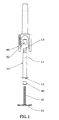
- the fluid dispenser of the The present invention advantageously comprises only five parts. It is a reservoir 10, advantageously produced in the form of a syringe body comprising a hollow body 11 provided with an upstream opening 12 and a downstream opening 13.
- the upstream opening 13 is sealed off by a plug 40 adapted to form the delivery piston when actuated via a rod actuator 30, while the downstream opening 13 is sealed in a sealed manner by a tip 50.
- the assembly formed by the syringe 10, the tip 50, the plug piston 40 and the actuating rod 30 is then fixed in an external body 80.
- the external body 80 incorporates the orifice of distribution 20 and is adapted to cooperate with the actuating rod 30 to ensure a correct actuation of the device.
- the external body 80 includes a window 89 at the level of the reservoir 10 for viewing the contents of said exterior from the outside tank. This characteristic is particularly advantageous in the case of a bidose because it allows to know if the first dose was distributed or not.
- the reservoir 10 is, as mentioned previously, preferably formed by a syringe body. This greatly facilitates the filling of the tank, since the filling syringes is well known and widely mastered by the manufacturers of fluid product. In this way, the syringe 10 is pre-filled and then its two openings upstream and downstream 12 and 13 are plugged by means of the piston plug 40 on the one hand and the end piece 50 on the other hand, so that the unit formed by the reservoir 10 and the two caps 40 and 50 can be pre-filled before the final assembly of the the invention. It is therefore not necessary to provide the manufacturer with a fluid product special tools to assemble a complicated device simultaneously with filling, or to fill an already assembled device
- the end piece 50 advantageously simultaneously provides three functions. On the one hand, it hermetically seals the downstream opening 13 of the syringe 10. On the other hand, it provides precompression during distribution. Finally, it includes means adapted to form a spray profile at the dispensing orifice 20 of the device for, upon actuation of the device, distribute so finely sprayed, the dose of product.
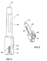
- This tip preferably made in one part made of an elastomeric material, is more precisely represented in FIGS. 6 to 9. It advantageously comprises a fixing part 54 for fixing on said opening 13 of the syringe 10, advantageously by snap-fastening.
- the tip 50 has other share a deformable shutter part 51 acting as a shutter at rest in sealing the syringe, said closure portion 51 being adapted to deform during actuation of the device, in particular under the effect of the pressure of the product, to open the downstream opening 13 of the reservoir and allow the expulsion of a dose of product.
- said shutter 51 is produced in the form of a stud 52 which fits tightly into a reduced diameter part of the outlet of the syringe 10, and which under the effect of the pressure of the product moves towards a part of larger diameter of said syringe outlet thus freeing the passage for the product.
- the end piece 50 also advantageously comprises a part spray 56 adapted to form a spray profile 55 during dispensing of the product.
- This spraying part 56 is advantageously produced in the form with a flat surface and can in particular be produced on the opposite side of the stud 52 forming the shutter 51.
- the lower part of the stud 52 forming the shutter 51 closes the syringe 10 while the upper part of the stud forming the spraying part 56 is arranged away from the end wall or bottom wall 81 of the member 80.
- this bottom wall 81 of the external member 80 incorporates spray channels or other suitable spray profiles, and when the pad 52 is deformed or moved to open the shutter part 51, as shown in the FIG.
- the spray profile 55 is therefore formed by the cooperation of the tip 50 and the external member 80.
- the wall bottom 81 of the external member 80 can then be planar and form the bottom of said profile.
- the device includes means for accumulating energy in the user's hand, preferably made between the external body 80 and the actuating rod 30.
- these energy storage means can be produced by small studs or pins 85 formed in the internal surface of the external member 80 and which cooperate with an actuating plate 35 integral with the rod 30 on which the user presses to move said actuating rod 30.
- a force predetermined is necessary to pass over these pins, so that the user stores energy in his fingers until he reaches this force, the energy being then suddenly released, guaranteeing the total distribution of the dose.
- These pins also act advantageously to prevent unwanted actuation of the device.
- the member outer 80 has two grooves in which the radial ends extend and said plate 35, thus preventing rotation of the actuating rod during actuation thereof.
- the external member 80 has two grooves which are offset on the periphery of the external member, so that to expel the second dose, it is necessary to rotate the actuating rod 30 to present the actuating plate 35 facing the second groove.
- similar energy storage means 85 are advantageously provided to guarantee the total expulsion of the second dose.
- the device also advantageously includes non-return means which act both on the axial displacement of the rod 30 and on the rotation movement of it.
- ramps 86 which allow the passage of the actuating plate 35 in one direction but prevents its movement In the opposite way.
- means may be provided to prevent actuation of the device and requiring a rotation prior to the rod actuation 30 before the first dose can be expelled.
- the present invention therefore provides a device for dispensing a fluid product, advantageously a bidose, which consists of only five pieces and which provides simultaneously all of the following functions: shutting off the tank outlet at rest and between the two doses; precompression when each dose is expelled; spraying of each dose by creating a spray profile at the time of distribution; accumulation of energy in the user's hand before each dose expulsion; transport security to prevent accidental activation; anti-return function after the first dose preventing the actuating rod from returning in its starting position; creation of an autonomous assembly consisting of the syringe, of the piston plug and the obturator end allowing a separate and easy filling of said syringe and providing a device in which the product is in contact only with two materials, namely the material of the syringe, generally glass, and that of the two plugs, generally an inert elastomeric material.
- the present invention has been described with reference to the drawings which represent a preferred embodiment thereof, but various variations and modifications could be made to the invention without departing from the scope thereof, as defined by the appended claims.
- a spring is armed which is then released by the actuation of a means of appropriate triggering, the spring then acting on the actuating rod 30 to expel the dose (s).
- the present invention is not limited to bidoses, but also applies to monodoses, and devices containing a limited number of doses, for example, three or four.
Landscapes
- Containers And Packaging Bodies Having A Special Means To Remove Contents (AREA)
- Infusion, Injection, And Reservoir Apparatuses (AREA)
Claims (12)
- Abgabevorrichtung für ein Fluid, die folgende Bestandteile umfaßt: Einen Behälter (10), der eine oder mehrere Dosen des Produktes enthält, eine Abgabeöffnung (20) und ein Abgabeorgan (30), wobei der Behälter (10) in Art einer Spritze aufgebaut ist und ein hohles Rohr (11) umfaßt, das mit einer stromaufwärts liegenden Öffnung (12) und einer stromabwärts liegenden Öffnung (13) versehen ist, wobei die stromaufwärts liegende Öffnung (12) einen Kolben (40) aufweist, der in der Ruhestellung einen dichten Stopfen bildet und mit einer Betätigungsstange (30) zusammenwirkt, die das Abgabeorgan bildet, und wobei die stromabwärts liegende Öffnung (13) ein Ansatzstück (50) umfaßt, das einerseits einen Verschluß (51) zur Bildung eines dichten Stopfens in der Ruhelage umfaßt und andererseits so ausgebildet ist, das es ein Zerstäubungsprofil (55) bei der Betätigung der Vorrichtung bildet, dadurch gekennzeichnet, daß das Ansatzstück (50) einen Befestigungsteil (54) umfaßt, der in dichter Weise auf der stromabwärts liegenden Öffnung (13) der Spritze (10) befestigt ist, so daß die Einheit, die von dem Behälter (10), dem Kolben (40) und dem Ansatzstück (50) gebildet wird, vor dem Zusammenbau der Vorrichtung vorgefüllt und dicht verschlossen werden kann, wobei die Spritze (10) und das Ansatzstück (50) beim Zusammenbau in einen äußeren Körper (80) eingefügt werden, der die Abgabeöffnung (20) der Vorrichtung umfaßt.
- Vorrichtung nach Anspruch 1, bei der das Ansatzstück (50) einen verformbaren Verschlußteil (51) umfaßt, der dazu dient, in der Ruhelage in dichter Weise die stromab liegende Öffnung (13) zu verschließen und sich bei einer Betätigung der Vorrichtung zu verformen, um die stromab liegende Öffnung (13) zu öffnen, sowie einen Zerstäubungsteil (56) zur Bildung eines Zerstäubungsprofils (55) bei der Abgabe des Produktes.
- Vorrichtung nach Anspruch 2, bei der der Zerstäubungsteil (56) des Ansatzstückes mit der Bodenwand (81) des äußeren Körpers (80) zusammenwirkt, um bei der Betätigung der Vorrichtung das Zerstäubungsprofil (55) zu definieren.
- Vorrichtung nach Anspruch 3, bei der das Ansatzstück (50) einen zylindrischen Zentralstöpsel (52) umfaßt, der einerseits den Verschluß (51) für die stromabwärts liegende Öffnung (13) der Spritze (10) und andererseits eine ebene Oberfläche (56) bildet, wobei der Stöpsel (52) bei der Betätigung der Vorrichtung in axialer Richtung verschoben wird, um einerseits die stromabwärts liegende Öffnung (13) der Spritze (10) zu öffnen und andererseits die ebene Oberfläche (56) gegen die Bodenwand (81) des äußeren Körpers (80) anzudrücken, die Verwirbelungskanäle (82) umfaßt, so daß der Stöpsel (52) bei der Betätigung das Zerstäubungsprofil (55) definiert.
- Vorrichtung nach einem der vorhergehenden Ansprüche, bei der das Ansatzstück (50) einstückig aus einem elastomeren Material hergestellt ist.
- Vorrichtung nach einem der vorhergehenden Ansprüche, bei der die Betätigungsstange (30), die durch den Verwender in axialer Richtung verschiebbar ist, um das Produkt abzugeben, mit einem äußeren Körper (80) zusammenwirkt, der mit Einrichtungen (85) zum Ansammeln von Energie versehen ist, um eine Energieansammlung in den Fingern des Verwenders zu erzeugen, die die Abgabe der gesamten Dosis während einer jeden Betätigung garantiert.
- Vorrichtung nach Anspruch 6, bei der der Körper (80) und die Betätigungsstange (30) zusammenwirken, um eine versehentliche Betätigung der Vorrichtung zu verhindern.
- Vorrichtung nach einem der vorhergehenden Ansprüche, bei der die Spritze (10) zwei Dosen des Produktes enthält und der äußere Körper (80) einen Anschlag in der axialen Bewegungsbahn der Betätigungsstange (30) bildet, um diese in zwei Teil-Bewegungsbahnen zu unterteilen, von denen jede jeweils einer Dosis entspricht.
- Vorrichtung nach Anspruch 8, bei der nach dem Ausstoßen der ersten Dosis die Betätigungsstange (30) bezüglich des äußeren Körpers (80) verdreht werden muß, um die zweite Dosis ausstoßen zu können.
- Vorrichtung nach Anspruch 9, bei der der äußere Körper (80) eine Rückkehrsperre (86) umfaßt, die mit der Stange (30) zusammenwirkt, um eine Drehung und/oder axiale Verschiebung der Stange (30) jeweils nur in einer einzigen Richtung zuzulassen.
- Vorrichtung nach einem der Ansprüche 8 bis 10, bei der der äußere Körper (80) in Höhe der Spritze ein Fenster (89) umfaßt, um die auszustoßende Dosis sichtbar zu machen.
- Vorrichtung nach den Ansprüchen 3 und 6, bei der der äußere Körper (80) einstückig ausgebildet ist.
Applications Claiming Priority (3)
| Application Number | Priority Date | Filing Date | Title |
|---|---|---|---|
| FR9906496 | 1999-05-21 | ||
| FR9906496A FR2793708B1 (fr) | 1999-05-21 | 1999-05-21 | Dispositif de distribution de produit fluide |
| PCT/FR2000/001321 WO2000071263A1 (fr) | 1999-05-21 | 2000-05-17 | Dispositif de distribution de produit fluide |
Publications (2)
| Publication Number | Publication Date |
|---|---|
| EP1185376A1 EP1185376A1 (de) | 2002-03-13 |
| EP1185376B1 true EP1185376B1 (de) | 2003-07-30 |
Family
ID=9545883
Family Applications (1)
| Application Number | Title | Priority Date | Filing Date |
|---|---|---|---|
| EP00927352A Expired - Lifetime EP1185376B1 (de) | 1999-05-21 | 2000-05-17 | Abgabevorrichtung für medien |
Country Status (5)
| Country | Link |
|---|---|
| US (1) | US6789750B1 (de) |
| EP (1) | EP1185376B1 (de) |
| DE (1) | DE60004218T2 (de) |
| FR (1) | FR2793708B1 (de) |
| WO (1) | WO2000071263A1 (de) |
Families Citing this family (43)
| Publication number | Priority date | Publication date | Assignee | Title |
|---|---|---|---|---|
| EP2264427B1 (de) | 1997-01-31 | 2017-05-03 | Xy, Llc | Optisches Gerät mit fokussierendem Reflektor zur Konvergenz der Strahlung auf einen Partikelfluss, und zugehöriges Analyseverfahren |
| US6149867A (en) | 1997-12-31 | 2000-11-21 | Xy, Inc. | Sheath fluids and collection systems for sex-specific cytometer sorting of sperm |
| US20030180351A1 (en) * | 1998-11-06 | 2003-09-25 | Reinhard Gluck | Pharmaceutically active composition and dispensing device |
| EP1092447B1 (de) * | 1999-10-14 | 2004-01-07 | Becton Dickinson and Company | Nasales Verabreichungsgerät mit Zerstäuberdüse |
| US7208265B1 (en) | 1999-11-24 | 2007-04-24 | Xy, Inc. | Method of cryopreserving selected sperm cells |
| IL152714A (en) | 2000-05-09 | 2014-03-31 | Xy Llc | High-purity spermatozoa populations carrying chromosome-x and chromosome-y |
| WO2002043486A1 (en) | 2000-11-29 | 2002-06-06 | Xy, Inc. | System for in-vitro fertilization with spermatozoa separated into x-chromosome and y-chromosome bearing populations |
| US7713687B2 (en) | 2000-11-29 | 2010-05-11 | Xy, Inc. | System to separate frozen-thawed spermatozoa into x-chromosome bearing and y-chromosome bearing populations |
| FR2837802B1 (fr) * | 2002-03-28 | 2005-01-21 | Valois Sa | Dispositif de distribution de produit fluide |
| US8486618B2 (en) | 2002-08-01 | 2013-07-16 | Xy, Llc | Heterogeneous inseminate system |
| JP4595067B2 (ja) | 2002-08-01 | 2010-12-08 | エックスワイ,エルエルシー | 低圧精子細胞分離システム |
| CA2534394C (en) | 2002-08-15 | 2013-01-08 | Xy, Inc. | High resolution flow cytometer |
| FR2847883A1 (fr) * | 2002-11-29 | 2004-06-04 | Valois Sas | Systeme et procede de bouchage d'un reservoir et distributeur de produit fluide incorporant un tel systeme |
| BRPI0408857B1 (pt) | 2003-03-28 | 2018-09-11 | Inguran Llc | aparelho, métodos e processos para separar partículas e para prover esperma de animal separado por sexo |
| GB2403153A (en) * | 2003-06-26 | 2004-12-29 | Bespak Plc | Hand held nasal dispensing device |
| DK2801363T3 (en) | 2004-03-29 | 2018-05-28 | Inguran Llc | PROCEDURE FOR STORING SORTED SPERMATOZOES |
| CA2574499C (en) | 2004-07-22 | 2016-11-29 | Monsanto Technology Llc | Process for enriching a population of sperm cells |
| US20060118167A1 (en) * | 2004-12-03 | 2006-06-08 | Xy, Inc. | Pressure regulated continuously variable volume container for fluid delivery |
| US7261559B2 (en) * | 2005-04-01 | 2007-08-28 | Ultradent Products, Inc. | Syringe delivery system for dispensing a dental composite or other highly viscous material |
| FR2883850B1 (fr) * | 2005-04-04 | 2007-05-25 | Mb Innovation Sarl | Dispositif de distribution d'au moins une dose d'un produit pateux ou fluide |
| AU2006235230B8 (en) * | 2005-04-07 | 2010-08-26 | Chata Biosystems, Inc. | Flow path conditioner system |
| GB2441129B (en) * | 2006-08-26 | 2008-11-26 | Norwich Pharma Technologies Ltd | Dosage Dispensing Canister |
| FR2908753B1 (fr) * | 2006-11-16 | 2011-11-11 | Becton Dickinson France | Dispositif pour delivrer automatiquement des doses successives de produit |
| US8119688B2 (en) * | 2007-09-19 | 2012-02-21 | Xy, Llc | Differential evaporation potentiated disinfectant system |
| US20100249166A1 (en) | 2007-09-19 | 2010-09-30 | Xy, Inc. | Differential evaporation potentiated disinfectant system |
| DK2240222T3 (en) | 2008-01-11 | 2018-06-25 | Ucb Biopharma Sprl | SYSTEMS FOR THE ADMINISTRATION OF PHARMACEUTICALS FOR PATIENTS WITH RHEUMATOID ARTHRITIS |
| WO2009144085A2 (en) * | 2008-04-18 | 2009-12-03 | Kuros Biosurgery Ag | Dispensing device, kit containing the device, and method of operating the device |
| SMT201900652T1 (it) | 2008-07-18 | 2020-01-14 | Ucb Biopharma Sprl | Sistemi per somministrare medicinale per pazienti con artrite reumatoide |
| USD641078S1 (en) | 2008-12-29 | 2011-07-05 | Ucb Pharma, S.A. | Medical syringe with needle tip cap |
| DE102009048551A1 (de) * | 2009-09-29 | 2011-04-07 | Ing. Erich Pfeiffer Gmbh | Austragvorrichtung und Montageverfahren hierfür |
| CH703422A1 (de) * | 2010-07-01 | 2012-01-13 | Medmix Systems Ag | Kombinierte Misch- und Austragvorrichtung. |
| FR2962351B1 (fr) * | 2010-07-09 | 2015-01-16 | Valois Sas | Tete de pulverisation pour dispositif de distribution de produit fluide. |
| WO2012119262A1 (en) * | 2011-03-04 | 2012-09-13 | Hoffmann Neopac Ag | Medical device for dispensing a medical or pharmaceutical product |
| CA142576S (fr) * | 2011-04-06 | 2012-05-29 | Valois Sas | Distributeur de produit fluide sublingual |
| USD684255S1 (en) * | 2011-04-06 | 2013-06-11 | Valois Sas | Sublingual fluid product dispenser |
| US9345866B2 (en) | 2011-05-13 | 2016-05-24 | Nipro Corporation | Nasal cavity administration container |
| GB2499612A (en) * | 2012-02-22 | 2013-08-28 | Consort Medical Plc | Syringe assembly with a stopper |
| GB2499611B (en) * | 2012-02-22 | 2015-09-16 | Consort Medical Plc | Valved container assembly |
| FR3016304B1 (fr) * | 2014-01-13 | 2018-03-09 | Aptar France Sas | Ensemble de distribution de produit fluide et procede d'utilisation d'un tel ensemble. |
| JP6558392B2 (ja) | 2017-04-04 | 2019-08-14 | ニプロ株式会社 | シリンジ型噴出装置 |
| FR3124096B1 (fr) | 2021-06-17 | 2026-03-06 | Aptar France Sas | Tête de pulvérisation pour dispositif de distribution de produit fluide |
| FR3127419B1 (fr) | 2021-09-27 | 2025-11-28 | Aptar France Sas | Ensemble de distribution de produit fluide |
| CN116077816B (zh) * | 2023-04-11 | 2023-06-16 | 无锡耐思生命科技股份有限公司 | 一种雾化喷头和喷雾装置 |
Family Cites Families (8)
| Publication number | Priority date | Publication date | Assignee | Title |
|---|---|---|---|---|
| US4161288A (en) * | 1976-10-05 | 1979-07-17 | Creative Dispensing Systems, Inc. | Fluid dispenser method and apparatus |
| DE7916475U1 (de) * | 1979-06-08 | 1979-10-18 | Hoechst Ag, 6000 Frankfurt | Spriihapplikator |
| DE4016126A1 (de) * | 1990-04-17 | 1991-10-24 | Coster Tecnologie Speciali Spa | Vorrichtung zur transnasalen oder oralen verabreichung von medikamenten o. dgl. |
| US5331954A (en) * | 1990-12-21 | 1994-07-26 | Novo Nordisk A/S | Device for nasal delivery of liquid medications |
| DE4202638A1 (de) * | 1991-06-19 | 1992-12-24 | Knop Ulrich Prof Dr Phil Nat | Elektro-injektions-manschette |
| US5601077A (en) * | 1991-08-07 | 1997-02-11 | Becton, Dickinson And Company | Nasal syringe sprayer with removable dose limiting structure |
| JP2930526B2 (ja) * | 1994-05-31 | 1999-08-03 | 株式会社キートロン | インジェクター型アトマイザー |
| FR2761281B1 (fr) | 1997-03-26 | 1999-05-21 | Valois Sa | Dispositif de pulverisation de produit fluide, tel q'un bidose |
-
1999
- 1999-05-21 FR FR9906496A patent/FR2793708B1/fr not_active Expired - Lifetime
-
2000
- 2000-05-17 EP EP00927352A patent/EP1185376B1/de not_active Expired - Lifetime
- 2000-05-17 WO PCT/FR2000/001321 patent/WO2000071263A1/fr not_active Ceased
- 2000-05-17 US US09/979,012 patent/US6789750B1/en not_active Expired - Fee Related
- 2000-05-17 DE DE60004218T patent/DE60004218T2/de not_active Expired - Lifetime
Also Published As
| Publication number | Publication date |
|---|---|
| DE60004218D1 (de) | 2003-09-04 |
| FR2793708A1 (fr) | 2000-11-24 |
| US6789750B1 (en) | 2004-09-14 |
| FR2793708B1 (fr) | 2001-08-03 |
| WO2000071263A1 (fr) | 2000-11-30 |
| EP1185376A1 (de) | 2002-03-13 |
| DE60004218T2 (de) | 2004-04-22 |
Similar Documents
| Publication | Publication Date | Title |
|---|---|---|
| EP1185376B1 (de) | Abgabevorrichtung für medien | |
| EP1185377B1 (de) | Abgabevorrichtung für medien | |
| EP0954485B1 (de) | Vorrichtung zur abgabe vom fliessfähigen produkt mit verschlussvorrichtung | |
| EP0721573B1 (de) | Dosiergerät zur abgabe von konstanten einheitlichen dosen | |
| EP1315576B1 (de) | Vorrichtung zur wiederholten abgabe von mediendosen | |
| EP3727534B1 (de) | Vorrichtung zur ausgabe eines fluidprodukts | |
| EP0670275A1 (de) | Dichtverschliessbare Abgabevorrichtung für einen Druck- oder Pumpbehälter | |
| EP4237050B1 (de) | Vorrichtung zur abgabe eines flüssigen produkts | |
| FR3068625B1 (fr) | Dispositif de distribution de produit fluide. | |
| FR3109887A1 (fr) | Dispositif de distribution de produit fluide | |
| EP1467788B1 (de) | Spender für flüssige stoffe | |
| EP1446233B1 (de) | Abgabevorrichtung für medien | |
| EP4514547A1 (de) | Vorrichtung zur abgabe eines flüssigen produkts und verfahren zum füllen davon | |
| EP1569859A1 (de) | Spender für flüssige stoffe | |
| EP1124646B1 (de) | Behälter mit verschluss- und füllvorrichtung und/oder sprühvorrichtung für flüssige produkte mit einem solchen behälter | |
| EP4472778B1 (de) | Vorrichtung zur abgabe eines flüssigen produkts und verfahren zum füllen davon | |
| FR3130623A1 (fr) | Dispositif de distribution de produit fluide | |
| FR2842791A1 (fr) | Reservoir de produit fluide et dispositif de distribution de produit fluide comportant un tel reservoir | |
| WO2009071823A1 (fr) | Valve amelioree | |
| EP3888797B1 (de) | Vorrichtung zum verteilen von flüssigen produkten | |
| FR2847834A1 (fr) | Dispositif de distribution de produit fluide | |
| EP3927403B1 (de) | Vorrichtung zur ausgabe eines fluidprodukts |
Legal Events
| Date | Code | Title | Description |
|---|---|---|---|
| PUAI | Public reference made under article 153(3) epc to a published international application that has entered the european phase |
Free format text: ORIGINAL CODE: 0009012 |
|
| 17P | Request for examination filed |
Effective date: 20011212 |
|
| AK | Designated contracting states |
Kind code of ref document: A1 Designated state(s): AT BE CH CY DE DK ES FI FR GB GR IE IT LI LU MC NL PT SE |
|
| GRAH | Despatch of communication of intention to grant a patent |
Free format text: ORIGINAL CODE: EPIDOS IGRA |
|
| RAP1 | Party data changed (applicant data changed or rights of an application transferred) |
Owner name: VALOIS S.A.S. |
|
| GRAH | Despatch of communication of intention to grant a patent |
Free format text: ORIGINAL CODE: EPIDOS IGRA |
|
| GRAA | (expected) grant |
Free format text: ORIGINAL CODE: 0009210 |
|
| AK | Designated contracting states |
Designated state(s): DE FR GB IT |
|
| REG | Reference to a national code |
Ref country code: GB Ref legal event code: FG4D Free format text: NOT ENGLISH |
|
| REG | Reference to a national code |
Ref country code: IE Ref legal event code: FG4D Free format text: FRENCH |
|
| REF | Corresponds to: |
Ref document number: 60004218 Country of ref document: DE Date of ref document: 20030904 Kind code of ref document: P |
|
| GBT | Gb: translation of ep patent filed (gb section 77(6)(a)/1977) | ||
| REG | Reference to a national code |
Ref country code: IE Ref legal event code: FD4D |
|
| PLBE | No opposition filed within time limit |
Free format text: ORIGINAL CODE: 0009261 |
|
| STAA | Information on the status of an ep patent application or granted ep patent |
Free format text: STATUS: NO OPPOSITION FILED WITHIN TIME LIMIT |
|
| 26N | No opposition filed |
Effective date: 20040504 |
|
| PGFP | Annual fee paid to national office [announced via postgrant information from national office to epo] |
Ref country code: IT Payment date: 20120522 Year of fee payment: 13 |
|
| REG | Reference to a national code |
Ref country code: FR Ref legal event code: CD Owner name: APTAR FRANCE SAS, FR Effective date: 20130104 |
|
| REG | Reference to a national code |
Ref country code: DE Ref legal event code: R082 Ref document number: 60004218 Country of ref document: DE Representative=s name: BITTNER & PARTNER, DE |
|
| PGFP | Annual fee paid to national office [announced via postgrant information from national office to epo] |
Ref country code: GB Payment date: 20130521 Year of fee payment: 14 Ref country code: DE Payment date: 20130513 Year of fee payment: 14 |
|
| REG | Reference to a national code |
Ref country code: DE Ref legal event code: R082 Ref document number: 60004218 Country of ref document: DE Representative=s name: BITTNER & PARTNER, DE Effective date: 20130614 Ref country code: DE Ref legal event code: R081 Ref document number: 60004218 Country of ref document: DE Owner name: APTAR FRANCE SAS, FR Free format text: FORMER OWNER: VALOIS S.A.S., LE NEUBOURG, FR Effective date: 20130614 Ref country code: DE Ref legal event code: R082 Ref document number: 60004218 Country of ref document: DE Representative=s name: BITTNER & PARTNER RECHTS- UND PATENTANWAELTE, DE Effective date: 20130614 |
|
| PG25 | Lapsed in a contracting state [announced via postgrant information from national office to epo] |
Ref country code: IT Free format text: LAPSE BECAUSE OF NON-PAYMENT OF DUE FEES Effective date: 20130517 |
|
| REG | Reference to a national code |
Ref country code: DE Ref legal event code: R119 Ref document number: 60004218 Country of ref document: DE |
|
| GBPC | Gb: european patent ceased through non-payment of renewal fee |
Effective date: 20140517 |
|
| REG | Reference to a national code |
Ref country code: DE Ref legal event code: R119 Ref document number: 60004218 Country of ref document: DE Effective date: 20141202 |
|
| PG25 | Lapsed in a contracting state [announced via postgrant information from national office to epo] |
Ref country code: DE Free format text: LAPSE BECAUSE OF NON-PAYMENT OF DUE FEES Effective date: 20141202 |
|
| REG | Reference to a national code |
Ref country code: FR Ref legal event code: PLFP Year of fee payment: 16 |
|
| PG25 | Lapsed in a contracting state [announced via postgrant information from national office to epo] |
Ref country code: GB Free format text: LAPSE BECAUSE OF NON-PAYMENT OF DUE FEES Effective date: 20140517 |
|
| REG | Reference to a national code |
Ref country code: FR Ref legal event code: PLFP Year of fee payment: 17 |
|
| REG | Reference to a national code |
Ref country code: FR Ref legal event code: PLFP Year of fee payment: 18 |
|
| REG | Reference to a national code |
Ref country code: FR Ref legal event code: PLFP Year of fee payment: 19 |
|
| PGFP | Annual fee paid to national office [announced via postgrant information from national office to epo] |
Ref country code: FR Payment date: 20190528 Year of fee payment: 20 |