EP1186308A2 - Dosierventile zur Abgabe von Flüssigkeiten - Google Patents
Dosierventile zur Abgabe von Flüssigkeiten Download PDFInfo
- Publication number
- EP1186308A2 EP1186308A2 EP01307641A EP01307641A EP1186308A2 EP 1186308 A2 EP1186308 A2 EP 1186308A2 EP 01307641 A EP01307641 A EP 01307641A EP 01307641 A EP01307641 A EP 01307641A EP 1186308 A2 EP1186308 A2 EP 1186308A2
- Authority
- EP
- European Patent Office
- Prior art keywords
- valve
- orifice
- metering valve
- valve plug
- vaporizable germicide
- Prior art date
- Legal status (The legal status is an assumption and is not a legal conclusion. Google has not performed a legal analysis and makes no representation as to the accuracy of the status listed.)
- Granted
Links
Images


Classifications
-
- A—HUMAN NECESSITIES
- A61—MEDICAL OR VETERINARY SCIENCE; HYGIENE
- A61L—METHODS OR APPARATUS FOR STERILISING MATERIALS OR OBJECTS IN GENERAL; DISINFECTION, STERILISATION OR DEODORISATION OF AIR; CHEMICAL ASPECTS OF BANDAGES, DRESSINGS, ABSORBENT PADS OR SURGICAL ARTICLES; MATERIALS FOR BANDAGES, DRESSINGS, ABSORBENT PADS OR SURGICAL ARTICLES
- A61L2/00—Disinfection or sterilisation of materials or objects, in general; Accessories therefor
- A61L2/16—Disinfection or sterilisation of materials or objects, in general; Accessories therefor using chemical substances
- A61L2/18—Liquid substances
- A61L2/186—Peroxide solutions
-
- A—HUMAN NECESSITIES
- A61—MEDICAL OR VETERINARY SCIENCE; HYGIENE
- A61L—METHODS OR APPARATUS FOR STERILISING MATERIALS OR OBJECTS IN GENERAL; DISINFECTION, STERILISATION OR DEODORISATION OF AIR; CHEMICAL ASPECTS OF BANDAGES, DRESSINGS, ABSORBENT PADS OR SURGICAL ARTICLES; MATERIALS FOR BANDAGES, DRESSINGS, ABSORBENT PADS OR SURGICAL ARTICLES
- A61L2/00—Disinfection or sterilisation of materials or objects, in general; Accessories therefor
- A61L2/02—Disinfection or sterilisation of materials or objects, in general; Accessories therefor using physical processes
- A61L2/14—Plasma, i.e. ionised gases
-
- A—HUMAN NECESSITIES
- A61—MEDICAL OR VETERINARY SCIENCE; HYGIENE
- A61L—METHODS OR APPARATUS FOR STERILISING MATERIALS OR OBJECTS IN GENERAL; DISINFECTION, STERILISATION OR DEODORISATION OF AIR; CHEMICAL ASPECTS OF BANDAGES, DRESSINGS, ABSORBENT PADS OR SURGICAL ARTICLES; MATERIALS FOR BANDAGES, DRESSINGS, ABSORBENT PADS OR SURGICAL ARTICLES
- A61L2/00—Disinfection or sterilisation of materials or objects, in general; Accessories therefor
- A61L2/26—Accessories
-
- A—HUMAN NECESSITIES
- A61—MEDICAL OR VETERINARY SCIENCE; HYGIENE
- A61L—METHODS OR APPARATUS FOR STERILISING MATERIALS OR OBJECTS IN GENERAL; DISINFECTION, STERILISATION OR DEODORISATION OF AIR; CHEMICAL ASPECTS OF BANDAGES, DRESSINGS, ABSORBENT PADS OR SURGICAL ARTICLES; MATERIALS FOR BANDAGES, DRESSINGS, ABSORBENT PADS OR SURGICAL ARTICLES
- A61L2202/00—Aspects relating to methods or apparatus for disinfecting or sterilising materials or objects
- A61L2202/10—Apparatus features
- A61L2202/12—Apparatus for isolating biocidal substances from the environment
- A61L2202/122—Chambers for sterilisation
-
- A—HUMAN NECESSITIES
- A61—MEDICAL OR VETERINARY SCIENCE; HYGIENE
- A61L—METHODS OR APPARATUS FOR STERILISING MATERIALS OR OBJECTS IN GENERAL; DISINFECTION, STERILISATION OR DEODORISATION OF AIR; CHEMICAL ASPECTS OF BANDAGES, DRESSINGS, ABSORBENT PADS OR SURGICAL ARTICLES; MATERIALS FOR BANDAGES, DRESSINGS, ABSORBENT PADS OR SURGICAL ARTICLES
- A61L2202/00—Aspects relating to methods or apparatus for disinfecting or sterilising materials or objects
- A61L2202/10—Apparatus features
- A61L2202/15—Biocide distribution means, e.g. nozzles, pumps, manifolds, fans, baffles, sprayers
-
- Y—GENERAL TAGGING OF NEW TECHNOLOGICAL DEVELOPMENTS; GENERAL TAGGING OF CROSS-SECTIONAL TECHNOLOGIES SPANNING OVER SEVERAL SECTIONS OF THE IPC; TECHNICAL SUBJECTS COVERED BY FORMER USPC CROSS-REFERENCE ART COLLECTIONS [XRACs] AND DIGESTS
- Y10—TECHNICAL SUBJECTS COVERED BY FORMER USPC
- Y10T—TECHNICAL SUBJECTS COVERED BY FORMER US CLASSIFICATION
- Y10T137/00—Fluid handling
- Y10T137/8593—Systems
- Y10T137/86493—Multi-way valve unit
- Y10T137/86863—Rotary valve unit
Definitions
- This invention relates to a metering valve for delivering liquid vaporizable germicide to a sterilizer.
- Sterilization is used in a broad range of industrial and medical applications. Sterilization is the complete destruction or the irreversible inactivation of all the microorganisms in the system. Sterilization can be performed, for example, with heat or chemical treatment. Heat sterilization is normally done using steam. Some equipment cannot withstand the heat or the moisture of stem treatment. As a result, chemical sterilization is now commonly used,
- Chemical sterilization can be done using alcohols, aldehydes such as formaldehyde, phenols, ozone, ethylene oxide, chlorine dioxide, or hydrogen peroxide. Hydrogen peroxide is commonly used for chemical sterilization.
- the vaporizable germicide vaporizes and is allowed to disperse throughout the chamber and onto the items to be sterilized. After a period of time, electrical energy is applied to an electrode to form a plasma to complete the sterilization cycle.
- the STERRAD® Sterilization is an exemplary hydrogen peroxide sterilization system, commercially available from Advanced Sterilization Products, Irvine, California. Advanced Sterilization Products is a Division of Ethicon Endo-Surgery, Inc.
- the system employs an automated delivery system in which a measured amount of the liquid germicide, typically aqueous hydrogen peroxide, is delivered to the sterilization chamber. Measured portions of the liquid germicide are provided in rupturable cells within a liquid cassette housing.
- the cassette and the delivery system are fully described in the Williams et al. patents, U.S. Patent Nos. 4,817,800, issued April 4, 1989; 4,913,196, issued April 3, 1990; 4,938,262, issued July 3, 1990; and 4,941,518, issued July 17, 1990, all of which are incorporated herein by reference.
- the delivery system is complex and expensive. There is a need for a delivery system which is simpler and less expensive than the cassette delivery system. Further, the volumes of vaporizable germicide which can be delivered to the sterilization chamber with the cassette delivery system are limited to incremental volumes of single cells on the cassette. For example, 1 1 ⁇ 2 cells of hydrogen peroxide cannot easily be delivered with the cassette delivery system.
- the amount of hydrogen peroxide required for sterilization depends on the size of the sterilization chamber, the quantity of equipment in the chamber to be sterilized, the materials from which the equipment to be sterilized is made, and many other factors, there are times when it would be useful to be able to add small additional increments of hydrogen peroxide into the sterilization chamber rather than being limited to adding an entire cell of vaporizable germicide from a cassette.
- the metering valve includes a body having at least a first and a second orifice; and a rotatable valve plug located in the body, where the rotatable valve plug prevents direct fluid communication between the first orifice and the second orifice.
- the valve plug includes at least one well, where the well comes into fluid communication separately with the first orifice and the second orifice as the valve plug is rotated.
- the orifices are located approximately 180 degrees apart in the valve body.
- the valve plug can be rotated manually or with a motor.
- the valve plug includes at least two wells. The two wells may have different sizes or shapes.
- the first orifice is never brought into direct fluid communication with the second orifice as said rotatable valve plug is rotated.
- the system includes a metering valve.
- the metering valve includes a body with at least two orifices and a rotatable valve plug located in the body.
- the valve plug prevents direct fluid communication between the two orifices.
- the valve plug includes at least one well. The well comes into fluid communication separately with the two or more orifices as the valve plug is rotated.
- the system also includes a reservoir connected to a first orifice on the metering valve. The reservoir contains vaporizable germicide.
- the system also includes a sterilization chamber, where the sterilization chamber receives vaporizable germicide from a second orifice on the metering valve.
- the system also includes a vaporizer connected to the second orifice on the metering valve.
- the vaporizer is in fluid communication with the sterilization chamber.
- the system also includes a vacuum pump connected to the sterilization chamber.
- the system may include a source of plasma.
- An accumulator may be located between the second orifice on the metering valve and the sterilization chamber.
- An on/off valve may optionally be located between the metering valve and the sterilization chamber and/or between the metering valve and the reservoir.
- the vaporizable germicide is hydrogen peroxide.
- the method includes providing a source of vaporizable germicide, a chamber, and a metering valve for delivering germicide to the chamber.
- the metering valve includes a body having at least two orifices and a rotatable valve plug located in the body. The valve plug prevents direct fluid communication between the two orifices.
- the metering valve is in fluid communication with the chamber and the source of vaporizable germicide. Rotating the valve plug transfers vaporizable germicide from the source of germicide into the well and from the well into the chamber.
- the method also includes reducing the pressure in the chamber.
- reducing the pressure vaporizes the vaporizable germicide, sterilizing the article in the chamber.
- the vaporizable germicide is accumulated in an accumulator located between the metering valve and the chamber.
- the article may be contacted with plasma.
- the vaporizable germicide is hydrogen peroxide.
- the method may also include opening or closing a valve between the metering valve and the source of vaporizable germicide or between the metering valve and the chamber.
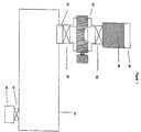
- FIG. 1 shows a schematic diagram of a sterilization chamber 10 with a metering valve 20 according to an embodiment of the invention.
- the sterilization chamber 10 and its components and methods of use are described in detail in U.S. Patent No. 4,756,882, issued July 12, 1988; U.S. Patent No. 5,656,238, issued August 12, 1997; and U.S. Patent No. 6,060,019, issued May 9, 2000, all of which are incorporated herein by reference.
- the metering valve 20 is mounted below a reservoir 24 which contains vaporizable germicide 26 and above a vaporizer 28 which is located above and which is fluidly attached to the sterilization chamber 10.
- Optional on/off valves 30 and 32 are located between the reservoir 24 and the metering valve 20 and/or between the metering valve 20 and the vaporizer 28.
- a vacuum pump 36 and a shutoff valve 40 are fluidly connected with the sterilization chamber 10.
- the metering valve 20 is described in the context of a metering valve for delivering vaporizable germicide to a sterilization chamber 10, it is to be understood that the application of the metering valve 20 to sterilization is illustrative only.
- the metering valve 20 of the present invention has many uses, and the example of delivering vaporizable germicide to a sterilization chamber 10 with the metering valve 20 is not meant to be limiting.
- the term germicide is meant to include either germicide or disinfectant.
- the metering valve 20 can be used to deliver liquids, solids, and slurries of solids in one or more liquids.
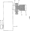
- Figure 2 shows a schematic diagram of a sterilization chamber 10 and metering valve 20 in which there are no optional on/off valves 30 and 32 located between the reservoir 24 and the metering valve 20 and between the metering valve 20 and the vaporizer 28.
- FIGS 3A and 3B show two views of a metering valve 20 according to an embodiment of the invention.
- the metering valve 20 has a generally rectangular shaped body 44 with open orifices 48 at a top and a bottom of the body 44.
- the two orifices 48 form an open tube extending through the body 44 of the metering valve 20.
- An roughly cylindrical valve plug channel 50 extends through the body 44 perpendicular to the first open tube formed by the two orifices 48.
- the valve plug channel 50 forms a second tube in the body 44 perpendicular to the first open tube formed by the two orifices 48.
- the valve plug channel 50 in Figures 3A and 3B contains a valve plug 52.
- the body 44 shown in Figures 3A and 3B has a roughly rectangular shape, the body 44 may have other shapes such as a cylindrical shape or other appropriate shapes.
- the valve plug 52 has a generally cylindrical center section, the barrel 56, with a rod-like valve stem 60 extending from an end of the barrel 56.
- a handle 64 is connected to the valve stem 60.
- a motor (not shown) can be connected to the valve stem 60 in place of, or in addition to, the handle 64.
- the tube formed by the two orifices 48 is plugged by the barrel 56 of the valve plug 52.
- the barrel 56 of the valve plug 52 prevents fluid communication between the two orifices 48 on the body 44 of the metering valve 20.
- the ends of the barrel 56 and the valve stems 60 form a seal with the body 44 of the metering valve 20.
- the valve plug 52 may be rotated in the body 44 of the metering valve 20 by turning the handle 60 or motor (not shown). The valve plug 52 is held in place in the body 44 of the metering valve 20.
- valve plug 52 can have other shapes.
- the valve plug 52 has the shape of a tapered cylinder rather than a simple cylinder, as in the embodiment shown in Figures 3A and 3B. What is important that the valve plug 52 block the fluid communication between the two orifices 48 and that the valve plug 52 provide a seal with the body 44 of the metering valve 20.
- a well 68 having a roughly semicircular shaped cross section in the barrel 56 of the valve plug 52 in the embodiment of the metering valve 20 shown in Figures 3A and 3B.
- the well 68 extends through only part of the barrel 56.
- the well 64 can have other cross-sectional shapes such as a rectangular shape, a V-shape, or a trapezoid shape.
- the well 68 is located under one of the orifices 48 when the valve plug 52 is placed in the body 44 of the metering valve 20 and when the well 68 is oriented so that the well 68 is oriented with an open side of the well 68 directed upward.
- the well 68 is not centered under the orifice 48 but is located asymmetrically below the orifice 48. At least a portion of the well 68 is in fluid communication with the orifice 48 when the open side of the well 68 is directed toward the orifice 48. Unlike a conventional valve, the orifices 48 of the metering valve 20 of Figures 3A and 3B are never in fluid communication with each other, no matter how the valve plug 52 is rotated.
- the size of the well 68 may depend on the size of the sterilization chamber 10.
- the well 68 has a size which is appropriate for holding an amount of vaporizable germicide 26 which is appropriate for the smallest sterilization chamber 10 to which the metering valve 10 is to be applied.
- the well 68 has a volume of approximately 1 milliliter. In embodiments appropriate for other sterilization chambers 10, the well 68 has a volume larger or smaller than 1 milliliter.
- Figures 4A and 4B show an alternative embodiment of the metering valve 20 in which there are two wells 68 in the barrel 56 of the valve plug 52.
- the wells 68 are positioned on the valve plug 52 so that at least a portion of each of the wells 68 is in fluid communication with an orifice 48 when the orifice 48 is aligned with the well 68.
- the two wells 68 are located on opposite sides of the valve plug 52.
- the two wells 68 of the metering valve 20 of Figures 4A and 4B are approximately 180° apart from each another.
- the wells 68 are at not 180° apart from each other, and only one of the wells 68 may be in fluid communication with an orifice 48 at any one time.
- rotating the valve plug 52 causes the other well 68 to be in fluid communication with the orifice 48.
- the wells 68 are not in direct fluid communication with each other, and the orifices 48 are not in direct fluid communication with each other.
- the wells 68 can have different sizes or shapes.
- the metering valve 20 can be made from a wide range of materials, including metal, glass, or plastic. Suitable metals include steel or aluminum. Stainless steel is an exemplary metal for forming the metering valve 20. TEFLONTM is an exemplary material for forming the metering valve 20. TEFLONTM is the tradename for polytetrafluoroethylene.
- valve plug 52 and the body 44 of the metering valve 20 can be achieved in several ways, depending on the material from which the metering valve is fabricated. If the valve plug 52 and the body 44 of the metering valve are both made of TEFLONTM, the valve plug 52 and the body 44 can be fabricated so that the contact between the TEFLONTM valve plug 52 and the TEFLONTM body 44 forms a seal.
- valve plug 52 is made of TEFLONTM, and the body 44 is made of metal. If the valve plug 52 and the body 44 are properly fabricated, the contact between the TEFLONTM valve plug 52 and the metal body 44 forms a seal.
- the valve plug 52 is made of TEFLONTM, and the body 44 is made of glass.
- both the valve plug 52 and the body 44 are made of metal. O-rings or packing can be placed on the valve plug 52 to form a seal between the valve plug 52 and the body 44.
- the O-rings or packing are preferably formed of a material which is resistant to the vaporizable germicide 26 which is used.
- VITONTM is an exemplary material for forming the O-rings or packing.
- TEFLONTM or silicone may also be used to form the O-rings or packing.
- vaporizable germicide 26 is placed in the reservoir 24 above the optional on/off valve 30.
- the vaporizable germicide 26 can be any liquid vaporizable germicide including hydrogen peroxide, peracetic acid, chlorine dioxide, ozone, or formaldehyde.
- the vaporizable germicide 26 comprises aqueous hydrogen peroxide.
- the vaporizable germicide 26 is approximately 59 wt% aqueous hydrogen peroxide.
- shutoff valve 40 between the vacuum pump 36 and the sterilization chamber 10 is opened, and the sterilization chamber 10 is evacuated to a pressure of less than 50 torr, more preferably less than 10 torr, and most preferably less than 1 torr with the vacuum pump 36. After the sterilization chamber 10 is evacuated, shutoff valve 40 between the vacuum pump 36 and the sterilization chamber 10 may be closed to isolate the sterilization chamber 10 from the vacuum pump 36. In an alternative embodiment which will be described in more detail later, the shutoff valve 40 between the vacuum pump 36 and the sterilization chamber 10 is left open.
- on/off valve 32 has been opened, allowing the vaporizable germicide 26 which was on top of the on/off valve 32 in Figure 6 to enter the vaporizer 28.
- the vaporizer 28 is fluidly connected to the interior of the sterilization chamber 10.
- the vaporizer is maintained at a temperature of 60 to 70° C.
- the vaporizable germicide 26 enters the hot vaporizer 28
- the vaporizable germicide 26 vaporizes, and the germicide vapor enters the sterilization chamber 10.
- the germicide vapor contacts the equipment to be sterilized (not shown) in the sterilization chamber 10, sterilizing the equipment.
- plasma is introduced into or is generated in the sterilization chamber 10 to enhance the sterilization by the germicide vapor or to remove the germicide residual.
- the handle 64 or the motor on the metering valve 20 can optionally be rotated more than one time. Each time the handle 64 is rotated, a volume of vaporizable germicide 26 equal to the volume of the well 68 is delivered to the top of the on/off valve 32. When the desired amount of vaporizable germicide 26 has been delivered to the top of the on/off valve 32, the on/off valve 32 is opened, allowing the vaporizable germicide 26 to enter the vaporizer 28. By knowing the volume of the well 68 and the number of times the handle 64 or motor has been rotated, the amount of vaporizable germicide 26 which has been delivered to the vaporizer 28 can be determined.
- each rotation of the handle 64 on the metering valve 20 delivers a volume of vaporizable germicide 26 equal to the volume of the two wells 68, rather than the volume of a single well 68.
- the embodiment of the metering valve 20 shown in Figures 3A and 3B thus delivers twice as much vaporizable germicide 26 for each rotation of the valve plug 52 as the embodiment of the metering valve 20 shown in Figures 3A and 3B.
- Vaporizable germicide 26 can enter the well 68 at the top of the metering valve 20 from the orifice 48 at the top of the metering valve 20 at the same time that vaporizable germicide 26 exits the well 68 at the bottom of the metering valve 20.
- the vaporizable germicide 26 enters the vaporizer 28 directly after leaving the well 68.
- the handle 64 on the metering valve 20 can be rotated multiple times to add more vaporizable germicide 26.
- the vaporizable germicide 26 enters the vaporizer 28 incrementally each time the handle 64 is rotated rather than at one time when the on/off valve 32 is opened.
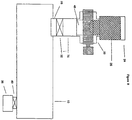
- Figure 8 shows another embodiment of the apparatus suitable for delivering larger volumes of vaporizable germicide 26 than the embodiment of the apparatus shown in Figure 1.
- An accumulator 76 is located between the metering valve 20 and the on/off valve 32 located above the vaporizer 28. The volume of the accumulator 76 is larger than the volume of the orifice 48 at the bottom of the metering valve 20.
- a larger volume of vaporizable germicide 26 can be placed on top of the on/off valve 32 above the vaporizer 28 than in the embodiment of the apparatus shown in Figure 1, where the volume of vaporizable germicide 26 on top of the on/off valve 32 is limited to the volume of the orifice 48 at the bottom of the metering valve 20.
- the on/off valve 32 is opened, delivering the vaporizable germicide 26 to the vaporizer 28.
- Accumulating larger volumes of vaporizable germicide 26 in the accumulator 76 of Figure 8 has advantages over simply allowing the vaporizable germicide 26 to enter the vaporizer 28 directly, when the vaporizable germicide 26 comprises hydrogen peroxide and water. Water has a higher vapor pressure than hydrogen peroxide.
- valve 40 between the sterilization chamber 10 and the vacuum pump 36 is left open when the on/off valve 32 is opened, allowing the vaporizable germicide 26 to enter the vaporizer 28, water is preferentially removed from the sterilization chamber 10 into the vacuum pump 36, because the water has a higher vapor pressure than hydrogen peroxide, and the vapor in the sterilization chamber 10 is enriched in water vapor compared to the vaporizable germicide 26 in the accumulator 76. Removing water from the aqueous hydrogen peroxide in the accumulator 76 by removing the water vapor in the sterilization chamber 10 concentrates the hydrogen peroxide.
- the valve 40 leading to the vacuum pump 36 is closed, and the concentrated hydrogen peroxide is allowed to vaporize from the vaporizer 28 into the sterilization chamber 10.
- the concentrated hydrogen peroxide in the vaporizer 28 vaporizes to produce a vapor which has a higher concentration of hydrogen peroxide than if water had not been removed from the aqueous hydrogen peroxide in the accumulator 76 by preferential vaporization.
- the concentrated hydrogen peroxide vapor is more effective at sterilization than hydrogen peroxide vapor produced from a less concentrated solution of aqueous hydrogen peroxide.
- Allowing the aqueous hydrogen peroxide vaporizable germicide to accumulate in the accumulator 76 is therefore a preferred embodiment.
- the aqueous hydrogen peroxide in the accumulator 76 can be concentrated by removing water vapor from the sterilization chamber 10 through the valve 40 and the vacuum pump 36, improving the effectiveness of the sterilization.
- the metering valve 20 of the present invention is an apparatus which provides a way to readily deliver a wide range of volumes of vaporizable germicide 26 to the sterilization chamber 10 without having to change the size of the delivery system, depending on the size of the sterilization chamber 10.
- the metering valve 20 of the present invention is a simple device which is inexpensive to manufacture and easy to use.
- the volume of vaporizable germicide 26 which is delivered to the vaporizer 28 can be controlled by rotating the handle 64 or motor (not shown) on the metering valve 20. Each rotation of the handle 64 delivers a volume of vaporizable germicide 26 equal to the volume of the well 68 on the valve plug 52.
- the incremental volumes of vaporizable germicide 26 to be delivered to the sterilization chamber 10 are not limited to the volume of a cell on a sterilization cassette. If multiple wells 68 are present on the valve plug 52, each rotation of the handle 64 delivers a volume of vaporizable germicide 26 equal to the volume of each well 68 times the number of wells 68 on the valve plug 52.
- more than one metering valve 20 may be located in parallel between the reservoir 24 and the vaporizer 28.
- the metering valves 20 can have wells 68 of differing sizes or shapes.
- the metering valve 20 can be selected for use which has a well 68 with a size which is optimal for the size of the sterilization chamber 10.
Landscapes
- Health & Medical Sciences (AREA)
- Public Health (AREA)
- Veterinary Medicine (AREA)
- General Health & Medical Sciences (AREA)
- Epidemiology (AREA)
- Life Sciences & Earth Sciences (AREA)
- Animal Behavior & Ethology (AREA)
- Chemical Kinetics & Catalysis (AREA)
- Plasma & Fusion (AREA)
- Engineering & Computer Science (AREA)
- Chemical & Material Sciences (AREA)
- Physics & Mathematics (AREA)
- General Chemical & Material Sciences (AREA)
- Apparatus For Disinfection Or Sterilisation (AREA)
- Devices For Dispensing Beverages (AREA)
- Multiple-Way Valves (AREA)
Applications Claiming Priority (2)
| Application Number | Priority Date | Filing Date | Title |
|---|---|---|---|
| US658312 | 2000-09-08 | ||
| US09/658,312 US6699434B1 (en) | 2000-09-08 | 2000-09-08 | Metering valve to deliver liquid |
Publications (3)
| Publication Number | Publication Date |
|---|---|
| EP1186308A2 true EP1186308A2 (de) | 2002-03-13 |
| EP1186308A3 EP1186308A3 (de) | 2002-03-20 |
| EP1186308B1 EP1186308B1 (de) | 2006-06-07 |
Family
ID=24640727
Family Applications (1)
| Application Number | Title | Priority Date | Filing Date |
|---|---|---|---|
| EP01307641A Expired - Lifetime EP1186308B1 (de) | 2000-09-08 | 2001-09-07 | Dosierventile zur Abgabe von Flüssigkeiten |
Country Status (7)
| Country | Link |
|---|---|
| US (1) | US6699434B1 (de) |
| EP (1) | EP1186308B1 (de) |
| JP (1) | JP2002206655A (de) |
| AU (1) | AU6881201A (de) |
| CA (1) | CA2356767C (de) |
| DE (1) | DE60120304T2 (de) |
| ES (1) | ES2265399T3 (de) |
Cited By (5)
| Publication number | Priority date | Publication date | Assignee | Title |
|---|---|---|---|---|
| EP1430909A3 (de) * | 2002-12-18 | 2005-07-20 | Luciano Salda | Sterilisiervorrichtung für Behälter |
| EP1870112A1 (de) * | 2006-06-21 | 2007-12-26 | Getinge Disinfection AB | Auslassvorrichtung für einen Desinfektionsapparat und Verfahren zur Flüssigkeitsübertragung |
| EP1870111A1 (de) * | 2006-06-21 | 2007-12-26 | Getinge Disinfection AB | Einlassvorrichtung für einen Desinfektionsapparat und Verfahren zur Flüssigkeitsübertragung |
| CN103071171A (zh) * | 2011-10-06 | 2013-05-01 | 佳能市场营销日本株式会社 | 灭菌装置、灭菌方法 |
| GB2508580A (en) * | 2012-10-10 | 2014-06-11 | Bio Productions Ltd | Tap for delivering a metered dose of fluid material |
Families Citing this family (12)
| Publication number | Priority date | Publication date | Assignee | Title |
|---|---|---|---|---|
| US20020187067A1 (en) * | 2001-05-24 | 2002-12-12 | Lukasik Robert G. | Adjustable accumulator |
| JP2005532072A (ja) * | 2002-07-10 | 2005-10-27 | マサチューセッツ・インスティテュート・オブ・テクノロジー | サンプルから核酸を単離するための装置および方法 |
| US7429353B2 (en) * | 2005-07-21 | 2008-09-30 | American Sterilizer Company | Method and apparatus for injecting a metered quantity of a liquid into a chamber |
| DE102007031962A1 (de) * | 2007-07-10 | 2009-01-15 | Krones Ag | Dosierventil |
| DE102007039008A1 (de) * | 2007-08-17 | 2009-02-26 | Khs Ag | Dosier- und Versorgungssystem für Vorrichtungen zum H2O2-Sterilisieren von Packmitteln, Vorrichtung mit einem solchen Dosier- und Versorgungssystem sowie Verfahren zum Betrieb einer solchen Vorrichtung |
| MX352578B (es) * | 2009-09-30 | 2017-11-29 | Tso3 Inc | Metodo y aparato de esterilizacion. |
| JP5846235B2 (ja) * | 2014-03-24 | 2016-01-20 | キヤノンマーケティングジャパン株式会社 | 滅菌装置、滅菌方法 |
| US10039850B2 (en) | 2016-01-13 | 2018-08-07 | Sterio3, Llc | Sterilization device and methods |
| EP3402540B1 (de) | 2016-01-13 | 2023-06-07 | SteriO3, LLC | Sterilisierungsvorrichtung und -verfahren |
| DE102017118836B3 (de) * | 2017-08-17 | 2019-01-17 | Marco Systemanalyse Und Entwicklung Gmbh | Dosiervorrichtung |
| CN109114432B (zh) * | 2018-09-30 | 2024-04-23 | 郑州忠林智能科技有限公司 | 自动化程度高的单井形式的容积式计量站 |
| US12116198B2 (en) | 2022-08-16 | 2024-10-15 | International Business Machines Corporation | Sterile storage, transport and delivery of fluids |
Family Cites Families (19)
| Publication number | Priority date | Publication date | Assignee | Title |
|---|---|---|---|---|
| US3650305A (en) | 1970-01-29 | 1972-03-21 | Harvey Dental Specialty Co | Valve for dispensing measured quantities of liquid |
| US3653266A (en) | 1970-03-05 | 1972-04-04 | Thiokol Chemical Corp | Dispenser valve for thick liquids or slurries |
| US3680736A (en) | 1970-08-05 | 1972-08-01 | Hans Viessmann | Rotary valve dispenser for tablets |
| GB2024158A (en) | 1977-09-08 | 1980-01-09 | Ici Ltd | Metering device |
| US4643876A (en) | 1985-06-21 | 1987-02-17 | Surgikos, Inc. | Hydrogen peroxide plasma sterilization system |
| US4744955A (en) | 1986-08-08 | 1988-05-17 | Shapiro Justin J | Adjustable volume pipette sampler |
| IT210397Z2 (it) | 1986-11-04 | 1988-12-30 | Ceresio Srl | Dispositivo per l'alimentazione controllata di solidi in liquidi. |
| US4938262A (en) | 1987-05-20 | 1990-07-03 | Johnson & Johnson Medical, Inc. | Fluid injection system |
| US4817800A (en) | 1987-05-20 | 1989-04-04 | Surgikos, Inc. | Fluid injection system cassette and fluid packaging methods |
| US4941518A (en) | 1987-05-20 | 1990-07-17 | Johnson & Johnson Medical, Inc. | Fluid injection system |
| US4913196A (en) | 1987-05-20 | 1990-04-03 | Surgikos, Inc. | Fluid injection system pumping methods |
| US4821929A (en) | 1988-02-19 | 1989-04-18 | Chalirmkiert Srisathapat | Dispenser |
| DE4214441C1 (de) | 1992-05-06 | 1993-12-09 | Waeschle Maschf Gmbh | Materialschleuse für Schüttgüter oder Flüssigkeiten |
| CA2146146C (en) * | 1992-10-01 | 2003-09-23 | Robert Warren Childers | Accumulator-based liquid metering system and method |
| US5348711A (en) * | 1993-07-21 | 1994-09-20 | Mdt Corporation | Dental handpiece sterilizer |
| GB2322431B (en) | 1997-01-22 | 2000-07-19 | Leslie Neville Reeves | Rotary valve constructions |
| US5887716A (en) | 1997-06-02 | 1999-03-30 | Johnson & Johnson Medical, Inc. | Liquid sterilant cassette and indicia system |
| US5882611A (en) | 1997-06-02 | 1999-03-16 | Ethicon, Inc. | Cassette and delivery system |
| US6273134B1 (en) * | 1999-11-01 | 2001-08-14 | Barnstead/Thermolyne Corporation | Sterilizer valve |
-
2000
- 2000-09-08 US US09/658,312 patent/US6699434B1/en not_active Expired - Fee Related
-
2001
- 2001-09-06 CA CA2356767A patent/CA2356767C/en not_active Expired - Fee Related
- 2001-09-07 EP EP01307641A patent/EP1186308B1/de not_active Expired - Lifetime
- 2001-09-07 AU AU68812/01A patent/AU6881201A/en not_active Abandoned
- 2001-09-07 DE DE60120304T patent/DE60120304T2/de not_active Expired - Lifetime
- 2001-09-07 ES ES01307641T patent/ES2265399T3/es not_active Expired - Lifetime
- 2001-09-10 JP JP2001273967A patent/JP2002206655A/ja active Pending
Cited By (10)
| Publication number | Priority date | Publication date | Assignee | Title |
|---|---|---|---|---|
| EP1430909A3 (de) * | 2002-12-18 | 2005-07-20 | Luciano Salda | Sterilisiervorrichtung für Behälter |
| EP1870112A1 (de) * | 2006-06-21 | 2007-12-26 | Getinge Disinfection AB | Auslassvorrichtung für einen Desinfektionsapparat und Verfahren zur Flüssigkeitsübertragung |
| EP1870111A1 (de) * | 2006-06-21 | 2007-12-26 | Getinge Disinfection AB | Einlassvorrichtung für einen Desinfektionsapparat und Verfahren zur Flüssigkeitsübertragung |
| WO2007147538A1 (en) * | 2006-06-21 | 2007-12-27 | Getinge Disinfection Ab | Inlet device for disinfection apparatus and method for liquid transfer |
| WO2007147537A3 (en) * | 2006-06-21 | 2009-02-12 | Getinge Disinfection Ab | Outlet device for disinfection apparatus and method for liquid transfer |
| CN101495158B (zh) * | 2006-06-21 | 2013-03-13 | 盖廷格消毒股份公司 | 消毒器的输出装置和液体输送方法 |
| US8790588B2 (en) | 2006-06-21 | 2014-07-29 | Getinge Disinfection Ab | Outlet device for disinfection apparatus and method for liquid transfer |
| CN103071171A (zh) * | 2011-10-06 | 2013-05-01 | 佳能市场营销日本株式会社 | 灭菌装置、灭菌方法 |
| CN103071171B (zh) * | 2011-10-06 | 2016-01-20 | 佳能市场营销日本株式会社 | 灭菌装置、灭菌方法 |
| GB2508580A (en) * | 2012-10-10 | 2014-06-11 | Bio Productions Ltd | Tap for delivering a metered dose of fluid material |
Also Published As
| Publication number | Publication date |
|---|---|
| ES2265399T3 (es) | 2007-02-16 |
| US6699434B1 (en) | 2004-03-02 |
| CA2356767C (en) | 2010-03-30 |
| AU6881201A (en) | 2002-03-14 |
| JP2002206655A (ja) | 2002-07-26 |
| EP1186308A3 (de) | 2002-03-20 |
| DE60120304T2 (de) | 2007-04-26 |
| DE60120304D1 (de) | 2006-07-20 |
| EP1186308B1 (de) | 2006-06-07 |
| CA2356767A1 (en) | 2002-03-08 |
Similar Documents
| Publication | Publication Date | Title |
|---|---|---|
| EP1186308B1 (de) | Dosierventile zur Abgabe von Flüssigkeiten | |
| ES2210455T3 (es) | Procedimiento de esterilizacion usando un pretratamiento de peroxido de hidrogeno. | |
| KR101863045B1 (ko) | 살균 방법 및 장치 | |
| JP6216450B2 (ja) | 滅菌装置及びこれを利用した滅菌方法 | |
| US20010033807A1 (en) | System and method for sterilizing a lumen device | |
| US8323582B2 (en) | Quantitative liquid injection device of plasma sterilizer | |
| KR101906102B1 (ko) | 화학적 멸균기를 위한 고효율 기화기 | |
| EP1260235B1 (de) | Einstellbarer Speicherbehälter | |
| AU642999B2 (en) | Method for sterilizing an enclosure with noncondensing hydrogen peroxide-containing gas | |
| AU2005237145A1 (en) | Metering valve to deliver liquid | |
| KR101980602B1 (ko) | 화학적 멸균기를 위한 고효율 기화기 |
Legal Events
| Date | Code | Title | Description |
|---|---|---|---|
| PUAI | Public reference made under article 153(3) epc to a published international application that has entered the european phase |
Free format text: ORIGINAL CODE: 0009012 |
|
| PUAL | Search report despatched |
Free format text: ORIGINAL CODE: 0009013 |
|
| AK | Designated contracting states |
Kind code of ref document: A2 Designated state(s): AT BE CH CY DE DK ES FI FR GB GR IE IT LI LU MC NL PT SE TR Kind code of ref document: A2 Designated state(s): DE ES FR GB IT |
|
| AX | Request for extension of the european patent |
Free format text: AL;LT;LV;MK;RO;SI |
|
| AK | Designated contracting states |
Kind code of ref document: A3 Designated state(s): AT BE CH CY DE DK ES FI FR GB GR IE IT LI LU MC NL PT SE TR |
|
| AX | Request for extension of the european patent |
Free format text: AL;LT;LV;MK;RO;SI |
|
| 17P | Request for examination filed |
Effective date: 20020902 |
|
| AKX | Designation fees paid |
Free format text: DE ES FR GB IT |
|
| 17Q | First examination report despatched |
Effective date: 20030123 |
|
| R17P | Request for examination filed (corrected) |
Effective date: 20020902 |
|
| GRAP | Despatch of communication of intention to grant a patent |
Free format text: ORIGINAL CODE: EPIDOSNIGR1 |
|
| GRAS | Grant fee paid |
Free format text: ORIGINAL CODE: EPIDOSNIGR3 |
|
| GRAA | (expected) grant |
Free format text: ORIGINAL CODE: 0009210 |
|
| AK | Designated contracting states |
Kind code of ref document: B1 Designated state(s): DE ES FR GB IT |
|
| RAP1 | Party data changed (applicant data changed or rights of an application transferred) |
Owner name: ETHICON, INC. |
|
| REG | Reference to a national code |
Ref country code: GB Ref legal event code: FG4D |
|
| REF | Corresponds to: |
Ref document number: 60120304 Country of ref document: DE Date of ref document: 20060720 Kind code of ref document: P |
|
| ET | Fr: translation filed | ||
| REG | Reference to a national code |
Ref country code: ES Ref legal event code: FG2A Ref document number: 2265399 Country of ref document: ES Kind code of ref document: T3 |
|
| PLBE | No opposition filed within time limit |
Free format text: ORIGINAL CODE: 0009261 |
|
| STAA | Information on the status of an ep patent application or granted ep patent |
Free format text: STATUS: NO OPPOSITION FILED WITHIN TIME LIMIT |
|
| 26N | No opposition filed |
Effective date: 20070308 |
|
| PGFP | Annual fee paid to national office [announced via postgrant information from national office to epo] |
Ref country code: GB Payment date: 20120905 Year of fee payment: 12 |
|
| PGFP | Annual fee paid to national office [announced via postgrant information from national office to epo] |
Ref country code: DE Payment date: 20120905 Year of fee payment: 12 Ref country code: IT Payment date: 20120914 Year of fee payment: 12 Ref country code: FR Payment date: 20120926 Year of fee payment: 12 |
|
| PGFP | Annual fee paid to national office [announced via postgrant information from national office to epo] |
Ref country code: ES Payment date: 20130813 Year of fee payment: 13 |
|
| GBPC | Gb: european patent ceased through non-payment of renewal fee |
Effective date: 20130907 |
|
| REG | Reference to a national code |
Ref country code: DE Ref legal event code: R119 Ref document number: 60120304 Country of ref document: DE Effective date: 20140401 |
|
| REG | Reference to a national code |
Ref country code: FR Ref legal event code: ST Effective date: 20140530 |
|
| PG25 | Lapsed in a contracting state [announced via postgrant information from national office to epo] |
Ref country code: GB Free format text: LAPSE BECAUSE OF NON-PAYMENT OF DUE FEES Effective date: 20130907 |
|
| PG25 | Lapsed in a contracting state [announced via postgrant information from national office to epo] |
Ref country code: IT Free format text: LAPSE BECAUSE OF NON-PAYMENT OF DUE FEES Effective date: 20130907 Ref country code: FR Free format text: LAPSE BECAUSE OF NON-PAYMENT OF DUE FEES Effective date: 20130930 Ref country code: DE Free format text: LAPSE BECAUSE OF NON-PAYMENT OF DUE FEES Effective date: 20140401 |
|
| REG | Reference to a national code |
Ref country code: ES Ref legal event code: FD2A Effective date: 20151028 |
|
| PG25 | Lapsed in a contracting state [announced via postgrant information from national office to epo] |
Ref country code: ES Free format text: LAPSE BECAUSE OF NON-PAYMENT OF DUE FEES Effective date: 20140908 |