EP1186389A2 - Procede de fabrication d'un article ceramique servant au bardage de structures de batiments, et dispositif de decoupage d'une dalle faite d'un melange plastique - Google Patents
Procede de fabrication d'un article ceramique servant au bardage de structures de batiments, et dispositif de decoupage d'une dalle faite d'un melange plastique Download PDFInfo
- Publication number
- EP1186389A2 EP1186389A2 EP00931780A EP00931780A EP1186389A2 EP 1186389 A2 EP1186389 A2 EP 1186389A2 EP 00931780 A EP00931780 A EP 00931780A EP 00931780 A EP00931780 A EP 00931780A EP 1186389 A2 EP1186389 A2 EP 1186389A2
- Authority
- EP
- European Patent Office
- Prior art keywords
- slab
- cutting
- blade
- end position
- separation plane
- Prior art date
- Legal status (The legal status is an assumption and is not a legal conclusion. Google has not performed a legal analysis and makes no representation as to the accuracy of the status listed.)
- Withdrawn
Links
- 238000005520 cutting process Methods 0.000 title claims abstract description 205
- 239000000919 ceramic Substances 0.000 title claims abstract description 54
- 239000000203 mixture Substances 0.000 title claims abstract description 30
- 238000004519 manufacturing process Methods 0.000 title claims description 25
- 238000005253 cladding Methods 0.000 title claims description 10
- 238000000926 separation method Methods 0.000 claims abstract description 54
- 239000000758 substrate Substances 0.000 claims abstract description 31
- 230000007246 mechanism Effects 0.000 claims abstract description 18
- 238000000034 method Methods 0.000 claims abstract description 17
- 238000013519 translation Methods 0.000 claims description 9
- 238000001035 drying Methods 0.000 claims description 7
- 230000001360 synchronised effect Effects 0.000 claims description 2
- 239000011449 brick Substances 0.000 description 9
- 238000012986 modification Methods 0.000 description 7
- 230000004048 modification Effects 0.000 description 7
- 238000010924 continuous production Methods 0.000 description 5
- 238000012545 processing Methods 0.000 description 5
- 239000004484 Briquette Substances 0.000 description 2
- 230000002950 deficient Effects 0.000 description 2
- 229910052500 inorganic mineral Inorganic materials 0.000 description 2
- 239000011707 mineral Substances 0.000 description 2
- 239000002245 particle Substances 0.000 description 2
- 239000004566 building material Substances 0.000 description 1
- 238000013461 design Methods 0.000 description 1
- 238000010304 firing Methods 0.000 description 1
Images

Classifications
-
- B—PERFORMING OPERATIONS; TRANSPORTING
- B28—WORKING CEMENT, CLAY, OR STONE
- B28B—SHAPING CLAY OR OTHER CERAMIC COMPOSITIONS; SHAPING SLAG; SHAPING MIXTURES CONTAINING CEMENTITIOUS MATERIAL, e.g. PLASTER
- B28B11/00—Apparatus or processes for treating or working the shaped or preshaped articles
- B28B11/14—Apparatus or processes for treating or working the shaped or preshaped articles for dividing shaped articles by cutting
- B28B11/16—Apparatus or processes for treating or working the shaped or preshaped articles for dividing shaped articles by cutting for extrusion or for materials supplied in long webs
-
- B—PERFORMING OPERATIONS; TRANSPORTING
- B26—HAND CUTTING TOOLS; CUTTING; SEVERING
- B26D—CUTTING; DETAILS COMMON TO MACHINES FOR PERFORATING, PUNCHING, CUTTING-OUT, STAMPING-OUT OR SEVERING
- B26D9/00—Cutting apparatus combined with punching or perforating apparatus or with dissimilar cutting apparatus
Definitions
- the invention relates to building materials and more specifically relates to a method for producing a ceramic article by plastic forming, namely to method for producing a ceramic article for cladding building structures and to device for cutting a slab of a plastic mixture.
- the high quality of front surface of articles for cladding building structures is the basic demand, required to facing articles; the price is also considered as important consumer characteristic.
- a forming mixture for producing fireproof ceramic articles by plastic forming, particularly bricks is a mixture, based on natural mineral argil with the humidity from 15 to 20%, that also includes burnt argil (chamotte) with the dimension of the particles from 0,01 to 5mm and more.
- Slab forming technological process is a continuous process. Continuous pushing of a forming mixture through a rectangular profile die of a soft -mud press results into a smooth surfaced slab. A slab is continuously feeding on the conveyer band and is moving practicallly horizontal to a device, cutting a slab into preforms. At that one surface of a slab while moving is in contact with a conveyer band.
- a bow with a tensioned string or a blade are used, i.e. cutting instrument with one cutting edge.
- Slab separation surfaces as a rule are located approximately vertical, perpendicular to external surfaces a slab or its moving direction.
- Preforms of ceramic articles are practically parallelepiped shaped briquettes.
- Slab dividing into preforms is performed by moving of cutting instrument cutting edges in one direction from the top surface of a slab to its bottom surface, contacting with the conveyer band, while rotation or translation of a string or of a blade.
- the slab is dividing essentially by a fixed string, and is relocating relatively to the slab separation plane from one vertical slab plane, being the side surface of a ceramic article, to its another side surface.
- This device comprises a horizontal substrate for receiving the portion of the slab to be cut, having at least one linear edge, positioning the vertical separation plane of the slab, and connected to a driver the cutting mechanism which bow with a tensioned string is mounted so as to be capable of rotation practically in the separation plane of the slab from one end position, where the string is located above the slab, into a second one, where the string is located under the slab, below the substrate.
- a slit between a substrate and conveyer band located approximately perpendicular to a slab moving direction, that positions a slab separation plane position, and along which a bow string is located.
- While slab cutting a string is moving in one direction from its top surface to bottom through a slit. While moving a string cutting edge in one direction plastic mixture is forced out from the top surface, where a string is entering on its bottom surface, on which it is exiting, and making barbs on preform edges along the cross-lines of these surfaces.
- Such cutting mechanism allows to use as a facing surface essentially only a top slab surface. So it is unprofitable to manufacture from such preforms facing tile by division briquette into two parts with a facing surfaces on each of it, because a tile, having slab bottom surface as a facing surface would be of low quality, essentially defective, so it almost on 50 % increases costs of tile manufacturing.
- the invention is based on the problem of developing a method for producing a ceramic article for cladding building structures, having that technological process of dividing a slab into briquette-like preforms, which would allow to get preforms without any barbs on the preform edges along perimeters at least of its two parallel surfaces, thereby to rise the quality of a ceramic article for cladding building structures and to reduce its manufacturing costs .
- the invention is also based on the problem of developing the device for cutting a slab of a plastic mixture with such cutting instrument, which when dividing a slab into briquette-like preforms would allow to get preforms without any barbs on the preform edges along perimeters at least of its two external parallel surfaces, and that would allow to use them as front surfaces of a ceramic article.
- the problem is solved by the fact that in the method for producing a ceramic article for cladding building structures by plastic forming that involves forming a slab of a plastic mixture and cutting the slab into briquette-like preforms while moving the cutting instrument cutting edge in the separation plane of the slab, by moving the cutting instrument or the slab in one direction from one end position to a second one and getting a ceramic article after preforms drying and burning, according to the invention, the additional cutting instrument is used, and when cutting the slab, cutting edge of the additional cutting instrument is moved in the separation plane of the slab from one end position to a second one towards moving direction of the cutting edge of the basic cutting instrument while the cutting-instruments cutting edges are brought into contact to align the positions of the cutting-instrument cutting edges on the separation surface along a line which is located between the two parallel surfaces of the slab, that being the front surfaces of a ceramic article.
- the cutting edges can brought into contact along a line that is approximately parallel to surfaces of the slab, that being the front surfaces of a ceramic article, or is inclined to these front surfaces not crossing them.
- cutting edges of basic and additional cutting instruments can also be located by the different sides of a contact line of cutting edges.
- the cutting edges of the basic or the additional cutting instruments can move in the separation plane of the slab by rotation relative to axes parallel to the longitudinal slab axis in the separation plane of the slab.
- the cutting edge of the basic or the additional cutting instruments it is possible also when cutting the slab, the cutting edge of the basic or the additional cutting instruments to move by rotation relative to axes parallel to the longitudinal slab axis and thereafter the cutting edge of another cutting instrument to move by translation in the separation plane of the slab.
- the disclosed method makes it possible to manufacture a ceramic article for cladding building structures having two smooth parallel surfaces, which may be used as front.
- the disclosed method makes it possible to decrease a quantity of defective articles and so to reduce the manufacturing costs of a ceramic article.
- the cutting mechanism comprises a blade that is mounted so as to be capable of rotation practically in the separation plane of the slab from one end position, where the blade cutting edge is located below the substrate into a second one, where the blade cutting edge is located above the substrate, between the horizontal surfaces of the slab, moreover in a second end position of the bow the string also is located between the horizontal surfaces of the slab, and is brought into contact with the blade .
- the bow and the blade to connect to the cutting mechanism driver so as to be capable of synchronous relocation from one end position into a second one.
- the substrate, the bow and the blade to mount so as to be capable of back-and-forth translation along the longitudinal axis of the slab, i.e. practically parallel to it, and to connect to a relocation driver.
- the device manufacturing comparing with the known requires low additional expenses.
- the device implementation in the automatic processing lines do not affect the production rate.
- the suggested method for producing a ceramic article for cladding building structures concludes in the following.
- a plastic forming mixture for producing fireproof ceramic article - facing tile or facing brick It may be any known composition of mixture for plastic forming and mainly - the mixture, based on mineral fireproof argil, with the humidity from 15 to 20%.
- the mixture can also include chamotte with particle size up to 5 mm and others known components. It is possible to use any other known plastic forming mixture.
- a plastic forming mixture is formed a slab with the smooth external surfaces, having in the cross section approximately rectangular shape.
- Slab forming technological process is a continuous process.
- a plastic forming mixture is continuously pushing through the rectangular profile die of a determined cross section and as a slab is feeding continuously to the conveyer band, that moves it to the device, cutting a slab to preforms, so that one of the horizontal slab surfaces while moving contacts with the conveyer band.
- a slab is cutting by cutting instruments into briquette-like preforms by detaching from the slab one preform or group of them simultaneously, while moving a cutting edges of one or group cutting instruments in separation planes, located approximately perpendicular to the longitudinal axes of a slab or its external surfaces.
- Blade or tensioned string (or wire) for example a bow, may be used as a cutting instrument.
- two cutting instruments - the basic and the additional: it may be two blades, two bows, and also a blade and a bow.
- Both cutting edges are located in one approximately perpendicular to the longitudinal axes of a slab plane, that is a slab separation plane.
- the cutting edges of said basic and additional cutting instruments are moving in the separation plane of the slab towards each other from one end position to a second one. It is thus possible to align the positions of the cutting-instrument cutting edges on the separation surface along a line, which is located between the two parallel surfaces of the slab, said surfaces being the front surfaces of a ceramic article.
- front surfaces are used briquette surfaces, having largest square. These surfaces may be place on the conveyer as vertically or as horizontally.
- a slab is cutting while moving cutting edges of a cutting instrument in separation surface by moving each cutting instrument in direction towards the slab from one end position to another one. It is possible to move a slab towards the cutting edges of a cutting instrument, for example, strings, tensed on the fixed base. The cutting edges are moving along the slab separation plane from one end position into another one in one direction.
- the cutting edges can be brought into contact along a line that is approximately parallel to surfaces of the slab, that being the front surfaces of a ceramic article.
- the contact line of the cutting edges may be inclined to the front surfaces not crossing these front surfaces.
- cutting edges of the basic and the additional cutting instruments can be located practically along a contact line of the cutting edges.
- cutting edges of the basic or the additional cutting instruments can be located practically along a contact line of the cutting edges and the edge of other cutting instrument may be displaced from a contact line towards its moving direction.
- cutting edges of the basic and the additional cutting instruments can also be located by the different sides of a contact line of the cutting edges.
- the cutting edges of the basic or the additional cutting instruments can move in the separation plane of the slab by rotation relative to axes parallel to the longitudinal slab axis.
- the cutting edges of the basic or the additional cutting instruments can move by rotation relative to axes parallel to the longitudinal slab axis and thereafter the cutting edge of another cutting instrument to move by translation in the separation plane of the slab.
- the preforms are dried and burnt.
- the drying and burning modes are well known.
- the facing brick is got just after the preforms burning.
- This facing brick has two parallel surfaces without barbs on its edges, both are smooth, and each of them may be used as the front surface, at that face-work is speed up.
- the preform after the burning is divided into two parts, each of that is a facing tile. It front surfaces at that are smooth and have no scratches. So the front surfaces in each part have no barbs on its edges. The probability of scoring at this surfaces is very small.
- the present method enables to low costs of the high quality facing tile manufactoring.
- the device for cutting a slab of a plastic mixture is mainly used in automatic continuous processing line.
- the suggested device comprises a horizontal substrate 1 (fig.1) for location the part of the slab 2 to be cut, that is the briquette-like preform 3 of a ceramic article being practically parallelepiped shaped.
- the substrate 1 has at least one linear edge, that positioning the vertical separation plane of the slab 2, which is approximately perpendicular to longitudinal axis of the slab 2.
- the substrate 1 may have a group of slit-like slots (not shown on fig.1) the number of which is equal to the number of the simultaneously cutting preforms. One edge of every slot positions the one vertical separation plane of the slab 2.
- a rectangular table located between the receiving and sending conveyers (not shown on fig.1). Cutting of the slab is accomplished by moving the table, speed of which is equal to the slab moving speed.
- the vertical separation plane of the slab 2 is located between the preform 3 and the remaining part of the slab 2.
- the device cutting mechanism comprises the bow 5 with a tensioned string 6 and the blade 7 with sharp cutting edge 8.
- the bow 5 is mounted so as to be capable of rotation from one end position into a second one practically in vertical separation plane of the slab, and is connected to the rotation driver.
- the blade 7 is also mounted so as to be capable of rotation from one end position into a second one practically in the same vertical separation plane of the slab, and is connected to the rotation driver.
- the bow 5 and the blade 7 have one common driver, providing their simultaneous turn at the opposite directions from one end position into a second one and back. It is possible to use different drivers in other modifications of the device.
- the bow 5 is mounted above the substrate 1, and one end of it is rigidly connected to the shaft 9 of the rotation driver (not shown on fig.1).
- the blade 7 is rigidly attached to the lever 10, that is located below the substrate 1.
- One end of the lever 10 is mounted so as to be capable of rotation at axis 11, another end is connected to the driver rotation shaft 9 of a bow 5.
- This connection includes the connecting-rod 12, the lever 13 and axes 14 and 15.
- the connecting-rod 12 is mounted so as to be capable of rotation in the plane approximately parallel to the separation plane of the slab 2.
- the ends of the connecting-rod 12 are mounted at the axes 14 and 15 of levers 10 and 13 thereafter.
- the lever 13 is rigidly connected to the shaft 9.
- the blade 7 and the bow 5 have one common rotation driver, providing their simultaneous relocation from one end position into a second one (shown the shaft 9 of the rotation driver). That is particularly important to get high quality of slab cutting while the substrate is moving.
- the shaft 9 and the axis 11 are located by different sides of slab 2.
- the shaft 9 is located by side surface B of the slab 2, and the axis 11 - by side surface B 1 .
- the substrate 1 (fig.2) for locating the portion of the slab 2 to be cut has the rectangular shape, that width is approximately equal to the width of the preform 3 of a ceramic article.
- the other part of the slab 2 is placed on the table 16 of receiving conveyer (not shown on the fig.2).
- the upper surfaces of the substrate 1 and of the table 16 lay essentially at the same horizontal plane.
- the substrate 1, the bow 5 and the blade 7 are mounted so as to be capable of alternative relocation along the axis of the slab 2, i.e. parallel it, and are connected with driver (not shown on the fig.2).
- a speed of the substrate 1, the bow 5 and the blade 7 are equal to a speed of the slab 2.
- the bow 5 and the blade 7 are shown on the fig.1,2 in the end position when portion of the slab 2 is cut.
- the string 6 is located above the substrate 1, essentially parallel to the edge 17, between the horizontal surfaces L and L 1 of the slab 2, that are the front surfaces of a ceramic article.
- its cutting edge 8 is located above the substrate 1 essentially parallel to the edge 17, between the surfaces L and L 1 of the slab 2.
- the distance between the string 6 and edge 8 may be from 2 to 10 mm.
- the blade 7 is placed by side of the preform 3 of a ceramic article, i.e.
- the minimum distance from one or another surfaces L or L 1 of a ceramic article to contact line of the string 6 and the blade 7, i.e. in the end position when the preform is cut, is choosing depending on the kind of a ceramic article. For example, making facing tile, this distance ought to high the tile thickness and making facing brick, it may be equal to a half of brick thickness. As it shown on the drawing, the distance s between the bottom surface L 1 and the edge 8, that is set on the level of the holes 4 of the preform 3, is more than the facing tile thickness.
- the bow 5 is determined for cutting the top part of the slab 2 from the side of the top surface L with the separation plane R
- the blade 7 is determined for cutting the bottom part of the slab 2 from the side of the bottom surface L 1 with the separation plane R 1 .
- This cutting mechanism implementation results in that while cutting the slab the forming mixture forced out by cutting edges is placed practically in the middle part of the preform 3 on the separation surface inside the longitudinal holes 4 in the area of contact line of the string 6 and the blade 7. This prevents barbs appearing along the edges of the front surfaces of a ceramic article, which are the cross-lines of the surfaces L and L 1 of the slab 2 and separation planes R and R 1 of the slab 2.
- the thickness of the string 6 and the blade 7 may be the same, moreover in other device modifications the string 6 may be placed on the side of the preform 3 of a ceramic article, i.e. the detached portion of the slab 2, and the blade 7 - on the side of the other part of the slab 2.
- the bow 5 and the blade 7 are shown in the end position before the cutting the slab 2.
- the string 6 is located above the surface L of the slab 2 and the angle a is the angle between the string 6 and the substrate 1.
- the blade 7 is located below the surface L 1 of the slab 2 and the angle b is the angle between the cutting edge 8 and the substrate 1.
- the angle a > the angle b .
- the bow 5 shank is rigidly connected to the driver shaft 9, and it is possible to change the angle a for cutting the slab 2 of another thickness.
- the lever 13 is rigidly connected to the driver shaft 9, the angle c is the angle between the lever 13 and the bow 5 shank, and it is possible to change the angle c by changing the angle b .
- the device is operating as follows: the slab 2 (fig.2) is continuously feeding from the die of soft-mud press (not shown on fig.2) on the receiving conveyer band, that is moving by the frictional force between the band and the slab 2.
- the slab 2 is cutting during the moving as all the device mechanisms and the substrate 1 are cinematically connected with the driver of their alternative motion.
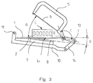
- the preform 3 (fig. 1,2) of a ceramic article is cut, the substrate 1, the table 16, the bow 5 and the blade 7 of cutting mechanism are moving from one end position to a second one, that is shown on fig. 3, to cut the next preform 3.
- the shaft 9 turns by rotation driver clockwise round the altitude axis, simultaneously causing in clockwise turning the bow 5 and the lever 13, to install the string 6 in original position.
- the suggested method can be used to produce by plastic forming the fireproof ceramic articles, such as facing brick, facing tile.
- the suggested device can be used for cutting a slab of a plastic mixture that is used for manufacturing fireproof ceramic articles, such as a facing brick, a facing tile and is mainly implemented in automatic continuous processing line.
Landscapes
- Engineering & Computer Science (AREA)
- Mechanical Engineering (AREA)
- Life Sciences & Earth Sciences (AREA)
- Forests & Forestry (AREA)
- Structural Engineering (AREA)
- Chemical & Material Sciences (AREA)
- Ceramic Engineering (AREA)
- Devices For Post-Treatments, Processing, Supply, Discharge, And Other Processes (AREA)
- Pharmaceuticals Containing Other Organic And Inorganic Compounds (AREA)
- Processing Of Stones Or Stones Resemblance Materials (AREA)
Applications Claiming Priority (3)
| Application Number | Priority Date | Filing Date | Title |
|---|---|---|---|
| RU99110612 | 1999-05-14 | ||
| RU99110612/03A RU2167761C2 (ru) | 1999-05-14 | 1999-05-14 | Способ изготовления керамического изделия для облицовки строительных конструкций и устройство для разрезания бруса из пластичной массы |
| PCT/RU2000/000173 WO2000070157A2 (fr) | 1999-05-14 | 2000-05-12 | Procede de fabrication d'un article ceramique servant au bardage de structures de batiments, et dispositif de decoupage d'une dalle faite d'un melange plastique |
Publications (1)
| Publication Number | Publication Date |
|---|---|
| EP1186389A2 true EP1186389A2 (fr) | 2002-03-13 |
Family
ID=20220114
Family Applications (1)
| Application Number | Title | Priority Date | Filing Date |
|---|---|---|---|
| EP00931780A Withdrawn EP1186389A2 (fr) | 1999-05-14 | 2000-05-12 | Procede de fabrication d'un article ceramique servant au bardage de structures de batiments, et dispositif de decoupage d'une dalle faite d'un melange plastique |
Country Status (3)
| Country | Link |
|---|---|
| EP (1) | EP1186389A2 (fr) |
| RU (1) | RU2167761C2 (fr) |
| WO (1) | WO2000070157A2 (fr) |
Families Citing this family (3)
| Publication number | Priority date | Publication date | Assignee | Title |
|---|---|---|---|---|
| ES2173807B1 (es) * | 2000-12-05 | 2003-12-16 | Carrocerias Esteva S A | Caseta modular transportable y puesto de socorro y/o asistencia medicarealizado a partir de tal caseta. |
| RU2323192C1 (ru) * | 2006-06-28 | 2008-04-27 | Александр Михайлович Ефремов | Слоистая структура из пластичного материала для получения керамической облицовочной плитки |
| RU2411121C1 (ru) * | 2009-11-23 | 2011-02-10 | Игорь Феликсович Шлегель | Устройство для резки пластичного бруса |
Family Cites Families (4)
| Publication number | Priority date | Publication date | Assignee | Title |
|---|---|---|---|---|
| GB1026610A (en) * | 1965-03-20 | 1966-04-20 | Mec Montoli Vincenzo Off | Shears |
| DE3341893C1 (de) * | 1983-11-19 | 1985-01-03 | C. Keller GmbH u. Co KG, 4530 Ibbenbüren | Verfahren und Vorrichtung zum Schneiden von Ziegelformlingen aus einem Tonstrang |
| RU2069621C1 (ru) * | 1990-12-17 | 1996-11-27 | Научно-технический центр "Строммаш" | Автомат-резчик керамического бруса |
| DE4215646C2 (de) * | 1992-05-13 | 1998-04-09 | Schmitz Tona Tonwerke | Vorrichtung zum Querschneiden eines weichplastischen Massestranges |
-
1999
- 1999-05-14 RU RU99110612/03A patent/RU2167761C2/ru not_active IP Right Cessation
-
2000
- 2000-05-12 WO PCT/RU2000/000173 patent/WO2000070157A2/fr not_active Ceased
- 2000-05-12 EP EP00931780A patent/EP1186389A2/fr not_active Withdrawn
Non-Patent Citations (1)
| Title |
|---|
| See references of WO0070157A3 * |
Also Published As
| Publication number | Publication date |
|---|---|
| WO2000070157A2 (fr) | 2000-11-23 |
| WO2000070157A3 (fr) | 2001-12-20 |
| RU2167761C2 (ru) | 2001-05-27 |
Similar Documents
| Publication | Publication Date | Title |
|---|---|---|
| CN103128779B (zh) | 装饰条嵌槽自动切槽机及其加工工艺 | |
| EP1186389A2 (fr) | Procede de fabrication d'un article ceramique servant au bardage de structures de batiments, et dispositif de decoupage d'une dalle faite d'un melange plastique | |
| KR20190140919A (ko) | 샘플링 장치, 판 부재 제조장치 및 석고계 건축재 제조장치 | |
| RU2354550C2 (ru) | Способ и установка для формования керамических плиток или панелей | |
| CN1772705A (zh) | 用于陶瓷产品生产的方法和系统 | |
| CN208840379U (zh) | 全自动并沟线夹输送装置及并沟线夹冲孔设备 | |
| CN1128554A (zh) | 深肋夹心板及其制造方法 | |
| CN2602902Y (zh) | 全自动切坯机 | |
| CN209477162U (zh) | 三极管引脚折弯机 | |
| US6381914B1 (en) | Roof tiles, roof tile layout, and method of manufacture | |
| CN112331431B (zh) | 一种陶瓷绝缘子加工流水线 | |
| CN1891420A (zh) | 瓷砖制作方法 | |
| CN210705163U (zh) | 一种板坯截断装置 | |
| CN217045826U (zh) | 一种磁瓦自动上料的宽度研磨装置及自动化生产线 | |
| CN221796151U (zh) | 一种用于沥青瓦输送的自动叠瓦机 | |
| CN222779756U (zh) | 一种抗形变实木板芯加工设备 | |
| JP4276591B2 (ja) | 無機質板の製造方法 | |
| CN222455636U (zh) | 一种潜水服面料切割开料机 | |
| CN1880036A (zh) | 方法及系统 | |
| CN224132173U (zh) | 一种加工链条的棒料进料装置 | |
| CN217393994U (zh) | 一种板材切割治具 | |
| CN221700380U (zh) | 一种叠瓦机上用的叠片输送机构 | |
| CN223043521U (zh) | 一种彩钢瓦生产弯曲机 | |
| CN216503403U (zh) | 卷料自动裁切钉装机 | |
| CN209906634U (zh) | 一种玻璃片掰断装置 |
Legal Events
| Date | Code | Title | Description |
|---|---|---|---|
| PUAI | Public reference made under article 153(3) epc to a published international application that has entered the european phase |
Free format text: ORIGINAL CODE: 0009012 |
|
| 17P | Request for examination filed |
Effective date: 20010213 |
|
| AK | Designated contracting states |
Kind code of ref document: A2 Designated state(s): AT BE CH CY DE DK ES FI FR GB GR IE IT LI LU MC NL PT SE |
|
| AX | Request for extension of the european patent |
Free format text: AL;LT;LV;MK;RO;SI |
|
| RBV | Designated contracting states (corrected) |
Designated state(s): AT DE ES FI FR IT |
|
| RAP1 | Party data changed (applicant data changed or rights of an application transferred) |
Owner name: CONAC INDUSTRY INC. |
|
| STAA | Information on the status of an ep patent application or granted ep patent |
Free format text: STATUS: THE APPLICATION IS DEEMED TO BE WITHDRAWN |
|
| 18D | Application deemed to be withdrawn |
Effective date: 20061201 |