EP1186894A1 - Winkelgeschwindigkeitssensor mit Referenzmarke - Google Patents
Winkelgeschwindigkeitssensor mit Referenzmarke Download PDFInfo
- Publication number
- EP1186894A1 EP1186894A1 EP01850155A EP01850155A EP1186894A1 EP 1186894 A1 EP1186894 A1 EP 1186894A1 EP 01850155 A EP01850155 A EP 01850155A EP 01850155 A EP01850155 A EP 01850155A EP 1186894 A1 EP1186894 A1 EP 1186894A1
- Authority
- EP
- European Patent Office
- Prior art keywords
- rotating body
- sensors
- teeth
- rotation
- tooth
- Prior art date
- Legal status (The legal status is an assumption and is not a legal conclusion. Google has not performed a legal analysis and makes no representation as to the accuracy of the status listed.)
- Withdrawn
Links
- 238000002485 combustion reaction Methods 0.000 claims abstract description 6
- 238000001208 nuclear magnetic resonance pulse sequence Methods 0.000 claims description 7
- 238000006073 displacement reaction Methods 0.000 claims description 4
- 230000003287 optical effect Effects 0.000 claims description 3
- 238000001514 detection method Methods 0.000 abstract description 2
- 239000000463 material Substances 0.000 description 3
- 238000010586 diagram Methods 0.000 description 2
- 230000005355 Hall effect Effects 0.000 description 1
- 239000004020 conductor Substances 0.000 description 1
- 230000035945 sensitivity Effects 0.000 description 1
Images

Classifications
-
- F—MECHANICAL ENGINEERING; LIGHTING; HEATING; WEAPONS; BLASTING
- F02—COMBUSTION ENGINES; HOT-GAS OR COMBUSTION-PRODUCT ENGINE PLANTS
- F02D—CONTROLLING COMBUSTION ENGINES
- F02D41/00—Electrical control of supply of combustible mixture or its constituents
- F02D41/0097—Electrical control of supply of combustible mixture or its constituents using means for generating speed signals
-
- F—MECHANICAL ENGINEERING; LIGHTING; HEATING; WEAPONS; BLASTING
- F02—COMBUSTION ENGINES; HOT-GAS OR COMBUSTION-PRODUCT ENGINE PLANTS
- F02D—CONTROLLING COMBUSTION ENGINES
- F02D41/00—Electrical control of supply of combustible mixture or its constituents
- F02D41/009—Electrical control of supply of combustible mixture or its constituents using means for generating position or synchronisation signals
-
- G—PHYSICS
- G01—MEASURING; TESTING
- G01D—MEASURING NOT SPECIALLY ADAPTED FOR A SPECIFIC VARIABLE; ARRANGEMENTS FOR MEASURING TWO OR MORE VARIABLES NOT COVERED IN A SINGLE OTHER SUBCLASS; TARIFF METERING APPARATUS; MEASURING OR TESTING NOT OTHERWISE PROVIDED FOR
- G01D5/00—Mechanical means for transferring the output of a sensing member; Means for converting the output of a sensing member to another variable where the form or nature of the sensing member does not constrain the means for converting; Transducers not specially adapted for a specific variable
- G01D5/12—Mechanical means for transferring the output of a sensing member; Means for converting the output of a sensing member to another variable where the form or nature of the sensing member does not constrain the means for converting; Transducers not specially adapted for a specific variable using electric or magnetic means
- G01D5/244—Mechanical means for transferring the output of a sensing member; Means for converting the output of a sensing member to another variable where the form or nature of the sensing member does not constrain the means for converting; Transducers not specially adapted for a specific variable using electric or magnetic means influencing characteristics of pulses or pulse trains; generating pulses or pulse trains
- G01D5/245—Mechanical means for transferring the output of a sensing member; Means for converting the output of a sensing member to another variable where the form or nature of the sensing member does not constrain the means for converting; Transducers not specially adapted for a specific variable using electric or magnetic means influencing characteristics of pulses or pulse trains; generating pulses or pulse trains using a variable number of pulses in a train
- G01D5/2454—Encoders incorporating incremental and absolute signals
- G01D5/2455—Encoders incorporating incremental and absolute signals with incremental and absolute tracks on the same encoder
- G01D5/2457—Incremental encoders having reference marks
-
- G—PHYSICS
- G01—MEASURING; TESTING
- G01P—MEASURING LINEAR OR ANGULAR SPEED, ACCELERATION, DECELERATION, OR SHOCK; INDICATING PRESENCE, ABSENCE, OR DIRECTION, OF MOVEMENT
- G01P13/00—Indicating or recording presence, absence, or direction, of movement
- G01P13/02—Indicating direction only, e.g. by weather vane
- G01P13/04—Indicating positive or negative direction of a linear movement or clockwise or anti-clockwise direction of a rotational movement
- G01P13/045—Indicating positive or negative direction of a linear movement or clockwise or anti-clockwise direction of a rotational movement with speed indication
-
- G—PHYSICS
- G01—MEASURING; TESTING
- G01P—MEASURING LINEAR OR ANGULAR SPEED, ACCELERATION, DECELERATION, OR SHOCK; INDICATING PRESENCE, ABSENCE, OR DIRECTION, OF MOVEMENT
- G01P3/00—Measuring linear or angular speed; Measuring differences of linear or angular speeds
- G01P3/42—Devices characterised by the use of electric or magnetic means
- G01P3/44—Devices characterised by the use of electric or magnetic means for measuring angular speed
- G01P3/48—Devices characterised by the use of electric or magnetic means for measuring angular speed by measuring frequency of generated current or voltage
- G01P3/481—Devices characterised by the use of electric or magnetic means for measuring angular speed by measuring frequency of generated current or voltage of pulse signals
-
- F—MECHANICAL ENGINEERING; LIGHTING; HEATING; WEAPONS; BLASTING
- F02—COMBUSTION ENGINES; HOT-GAS OR COMBUSTION-PRODUCT ENGINE PLANTS
- F02D—CONTROLLING COMBUSTION ENGINES
- F02D2250/00—Engine control related to specific problems or objectives
- F02D2250/06—Reverse rotation of engine
-
- F—MECHANICAL ENGINEERING; LIGHTING; HEATING; WEAPONS; BLASTING
- F02—COMBUSTION ENGINES; HOT-GAS OR COMBUSTION-PRODUCT ENGINE PLANTS
- F02D—CONTROLLING COMBUSTION ENGINES
- F02D2400/00—Control systems adapted for specific engine types; Special features of engine control systems not otherwise provided for; Power supply, connectors or cabling for engine control systems
- F02D2400/08—Redundant elements, e.g. two sensors for measuring the same parameter
Definitions
- the invention concerns an arrangement to detect the angular position, the angular speed and the direction of rotation of an axis of a rotating body.
- the rotating body can be constituted by, for example, a flywheel in an internal combustion engine or a toothed wheel attached to a shaft of a motor.
- the invention concerns a new arrangement to detect the angular position, the angular speed and the direction of rotation of an axis of a rotating body, which arrangement is simple to produce, can be made small and compact, is easy and cheap to mount and only requires normal, simple circuit components (sequential logic) for the signal processing.
- the invention is particularly applicable for the flywheel of an internal combustion engine or at a toothed wheel attached to a shaft in a motor.
- the invention can be used on a motorcycle where a compact position sensor is needed that provides information about the position of the crankshaft (the position of the pistons) and the angular speed in order to be able to generate an ignition position with very high precision.
- the task is carried out in that the arrangement comprises at least two sensors, which are located at a distance from each other both with respect to the direction of rotation and with respect to the axial direction.
- the sensors may be magnetic and/or optosensors or capacitive sensors, and they are arranged to give pulses when "teeth" on the outer surface of the rotating body pass them during the rotation. A part of at least one tooth has been removed in the axial direction of the rotating body, or, alternatively, the space between two teeth may be only partially filled in the axial direction of the rotating body.
- the sensors are arranged to measure with a time displacement of various parts of each tooth, whereby the pulse sequences will be different for clockwise and for anti-clockwise rotation.
- Figure 1 shows a sketch of the principle of the location of the teeth and sensors where the axis of the rotating body runs perpendicular to the plane of the drawing.
- Figure 2 shows a rotating body in which the axis of the rotating body lies parallel to the plane of the drawing.
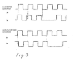
- FIG. 3 shows diagrams of the trigger pulses and the reference pulses according to one embodiment of the invention.
- reference symbol 1 denotes "teeth” arranged at regular intervals on the rotating body.
- the teeth may comprise magnetic conducting material and/or optically reflecting material or material that can be detected capacitively according to the type of sensor that is to detect them when they pass the sensors 2 during rotation of the rotating body in the direction of the arrow.
- the rotating body rotates in the direction shown by the arrow around an axis that is suggested in Figure 1.
- the teeth 1 may protrude from or be embedded in the outer surface of the rotating body, or they may be arranged in some other manner such that they can be detected by sensors 2 that are arranged in co-operation with the teeth.
- the teeth 1 do not necessarily have the shape shown in the drawing, but may be designed in another way that is suitable for giving pulses when they pass the sensors 2.
- One part of at least one tooth has a different design.
- the tooth 3 is half the size of other teeth 1, see Figure 2.
- the different tooth 3 is designed such that a sensor 2a that is arranged to detect the missing part of the different tooth will be able to give a pulse sequence that is different from the pulse sequence of a second sensor 2b that is arranged to detect the regularly arranged teeth.
- the different tooth will be able to provide a reference pulse.
- the different tooth may also be designed by partially filling in the space between two teeth. For example, the space may be filled to half its extent in the axial direction.
- the number of teeth may be even or odd.
- the teeth may also be located on the inner surface of the rotating body if it is hollow. In this case, it is appropriate that the sensors are also arranged inside the rotating body.
- two sensors 2a and 2b have been arranged. It is appropriate to locate the sensors 2a and 2b next to each other on a support (not shown). The support is placed at an angle such that one sensor, sensor 2b in the case shown here, is arranged somewhat in front of the second sensor 2a with respect to the direction of rotation. Furthermore, the sensor 2a is located such that it detects that part of the different tooth 3 that has been removed. Sensor 2b, on the other hand, measures that part of the tooth 3 that has not been removed, that is, sensor 2b gives a regular pulse sequence, while sensor 2a gives a pulse sequence containing a gap, see Figure 3. The sensors 2a and 2b thus measure with a time displacement on different parts of the respective teeth. The pulse sequences will be different for clockwise and for anti-clockwise rotation, see Figure 3.
- the sensors may be magnetic sensors and/or optical sensors or capacitive sensors, whereby the teeth are correspondingly arranged with magnetic transmitters, optical transmitters or capacitive transmitters. If Hall effect transmitters, for example, are used, it is possible to reduce the rate of revolution in order to detect the zero position.
- Figure 3 shows a pulse diagram for the embodiment shown in Figures 1 and 2, where the material of the tooth 3 has been removed and the sensors, that is, the angle detector, has been rotated according to Figure 2.
- a "zero pulse” or reference pulse can be determined with the aid of the different tooth.
- the angle that is, the position of the shaft, and the speed and/or the direction of rotation can be determined given knowledge of the number of teeth and the appearance of the different tooth. Circuits for this are not shown, since such circuits are well known to one skilled in the arts.
- the sensors are arranged on a supporting unit, which is located in association with the outer surface of the rotating body.
- the sensors may be placed next to each other, whereby the unit is placed at an angle relative to the axis of the rotating body in order to obtain the desired displacement both in the direction of rotation and in the axial direction.
- the sensors may also be arranged displaced and at an angle to each other on the support, which in this case does not then need to be placed at an angle.
- the supporting unit is arranged in a surrounding cover, whereby the complete cover can be adjusted with respect to the axis of the rotating body.
- optocouplers may be used for the inputs.
Landscapes
- Engineering & Computer Science (AREA)
- Physics & Mathematics (AREA)
- General Physics & Mathematics (AREA)
- Chemical & Material Sciences (AREA)
- Combustion & Propulsion (AREA)
- Mechanical Engineering (AREA)
- General Engineering & Computer Science (AREA)
- Measurement Of Length, Angles, Or The Like Using Electric Or Magnetic Means (AREA)
- Indicating Or Recording The Presence, Absence, Or Direction Of Movement (AREA)
- Transmission And Conversion Of Sensor Element Output (AREA)
Applications Claiming Priority (2)
| Application Number | Priority Date | Filing Date | Title |
|---|---|---|---|
| SE0003169A SE0003169L (sv) | 2000-09-07 | 2000-09-07 | Triggivare |
| SE0003169 | 2000-09-07 |
Publications (1)
| Publication Number | Publication Date |
|---|---|
| EP1186894A1 true EP1186894A1 (de) | 2002-03-13 |
Family
ID=20280928
Family Applications (1)
| Application Number | Title | Priority Date | Filing Date |
|---|---|---|---|
| EP01850155A Withdrawn EP1186894A1 (de) | 2000-09-07 | 2001-09-07 | Winkelgeschwindigkeitssensor mit Referenzmarke |
Country Status (2)
| Country | Link |
|---|---|
| EP (1) | EP1186894A1 (de) |
| SE (1) | SE0003169L (de) |
Cited By (8)
| Publication number | Priority date | Publication date | Assignee | Title |
|---|---|---|---|---|
| FR2871880A1 (fr) * | 2004-06-18 | 2005-12-23 | Siemens Vdo Automotive Sas | Dispositif et un procede pour determiner la position d'un moteur |
| FR2875297A1 (fr) * | 2004-09-13 | 2006-03-17 | Sc2N Sa | Capteur d'angle intelligent pour systeme de retour automatique d'indicateur de changement de direction |
| DE102005002356A1 (de) * | 2005-01-18 | 2006-07-27 | Siemens Ag | Vorrichtung zum Erfassen der Winkelposition einer Kurbelwelle einer Brennkraftmaschine |
| WO2006009298A3 (en) * | 2004-07-20 | 2006-08-24 | Toyota Motor Co Ltd | Reverse rotation detector for internal combustion engine |
| US7184876B2 (en) | 2004-06-18 | 2007-02-27 | Siemens Vdo Automotive | Device and process for determining the position of an engine |
| WO2016064330A1 (en) * | 2014-10-23 | 2016-04-28 | Scania Cv Ab | Device for detecting speed of a rotatable element, method and vehicle |
| DE102017128183A1 (de) * | 2017-11-28 | 2019-05-29 | Bdr Thermea Group B.V. | Verfahren zur Steuerung einer Brennkraftmaschine in einem Blockheizkraftwerk und Vorrichtung zur Erfassung von Betriebsparametern einer Brennkraftmaschine in einem Blockheizkraftwerk |
| WO2019110183A1 (de) * | 2017-12-06 | 2019-06-13 | Robert Bosch Gmbh | Sensoranordnung zur bestimmung mindestens einer rotationseigenschaft eines um mindestens eine rotationsachse rotierenden elements |
Citations (7)
| Publication number | Priority date | Publication date | Assignee | Title |
|---|---|---|---|---|
| JPS5530610A (en) * | 1978-08-25 | 1980-03-04 | Tdk Corp | Angular signal detector |
| DE3031357A1 (de) * | 1980-08-20 | 1982-04-08 | Robert Bosch Gmbh, 7000 Stuttgart | Kombinierte inkrement- und bezugsmarkenerkennung fuer eine rotierende welle, insbesondere die kurbelwelle einer brennkraftmaschine |
| US4369405A (en) * | 1979-07-10 | 1983-01-18 | Nippondenso Co., Ltd. | Rotational position detecting apparatus |
| EP0419040A1 (de) * | 1989-09-19 | 1991-03-27 | Texas Instruments Incorporated | Weg-/Geschwindigkeitsgeber unter Benutzung des Magnetowiderstandseffektes |
| US5336996A (en) * | 1992-08-21 | 1994-08-09 | The Duriron Company, Inc. | Hall effect monitoring of wear of bearing supporting a rotor within a stationary housing |
| US5644226A (en) * | 1994-03-02 | 1997-07-01 | Nippondenso Co., Ltd. | Magnetic detector having a bias magnet and magnetoresistive elements shifted away from the center of the magnet |
| US5719496A (en) * | 1995-06-07 | 1998-02-17 | Durakool Incorporated | Dual-element proximity sensor for sensing the direction of rotation of a ferrous target wheel |
-
2000
- 2000-09-07 SE SE0003169A patent/SE0003169L/xx not_active Application Discontinuation
-
2001
- 2001-09-07 EP EP01850155A patent/EP1186894A1/de not_active Withdrawn
Patent Citations (7)
| Publication number | Priority date | Publication date | Assignee | Title |
|---|---|---|---|---|
| JPS5530610A (en) * | 1978-08-25 | 1980-03-04 | Tdk Corp | Angular signal detector |
| US4369405A (en) * | 1979-07-10 | 1983-01-18 | Nippondenso Co., Ltd. | Rotational position detecting apparatus |
| DE3031357A1 (de) * | 1980-08-20 | 1982-04-08 | Robert Bosch Gmbh, 7000 Stuttgart | Kombinierte inkrement- und bezugsmarkenerkennung fuer eine rotierende welle, insbesondere die kurbelwelle einer brennkraftmaschine |
| EP0419040A1 (de) * | 1989-09-19 | 1991-03-27 | Texas Instruments Incorporated | Weg-/Geschwindigkeitsgeber unter Benutzung des Magnetowiderstandseffektes |
| US5336996A (en) * | 1992-08-21 | 1994-08-09 | The Duriron Company, Inc. | Hall effect monitoring of wear of bearing supporting a rotor within a stationary housing |
| US5644226A (en) * | 1994-03-02 | 1997-07-01 | Nippondenso Co., Ltd. | Magnetic detector having a bias magnet and magnetoresistive elements shifted away from the center of the magnet |
| US5719496A (en) * | 1995-06-07 | 1998-02-17 | Durakool Incorporated | Dual-element proximity sensor for sensing the direction of rotation of a ferrous target wheel |
Non-Patent Citations (1)
| Title |
|---|
| PATENT ABSTRACTS OF JAPAN vol. 004, no. 062 (P - 010) 9 May 1980 (1980-05-09) * |
Cited By (15)
| Publication number | Priority date | Publication date | Assignee | Title |
|---|---|---|---|---|
| US7184876B2 (en) | 2004-06-18 | 2007-02-27 | Siemens Vdo Automotive | Device and process for determining the position of an engine |
| WO2005124287A1 (fr) * | 2004-06-18 | 2005-12-29 | Siemens Vdo Automotive | Dispositif et un procede pour determiner la position d’un moteur |
| KR101226176B1 (ko) * | 2004-06-18 | 2013-01-24 | 콘티넨탈 오토모티브 프랑스 | 내연기관의 위치를 결정하기 위한 장치 및 방법 |
| CN100529676C (zh) * | 2004-06-18 | 2009-08-19 | 法国欧陆汽车公司 | 用于确定发动机位置的装置和方法 |
| FR2871880A1 (fr) * | 2004-06-18 | 2005-12-23 | Siemens Vdo Automotive Sas | Dispositif et un procede pour determiner la position d'un moteur |
| US7444262B2 (en) | 2004-07-20 | 2008-10-28 | Toyota Jidosha Kabushiki Kaisha | Reverse rotation detector for internal combustion engine |
| WO2006009298A3 (en) * | 2004-07-20 | 2006-08-24 | Toyota Motor Co Ltd | Reverse rotation detector for internal combustion engine |
| CN100590436C (zh) * | 2004-07-20 | 2010-02-17 | 丰田自动车株式会社 | 用于内燃机的反转检测装置 |
| FR2875297A1 (fr) * | 2004-09-13 | 2006-03-17 | Sc2N Sa | Capteur d'angle intelligent pour systeme de retour automatique d'indicateur de changement de direction |
| EP1635148A3 (de) * | 2004-09-13 | 2016-06-15 | Sc2N | Intelligenter Winkelsensor für das automatische Rückstellungssystem eines Richtungsanzeigers |
| DE102005002356A1 (de) * | 2005-01-18 | 2006-07-27 | Siemens Ag | Vorrichtung zum Erfassen der Winkelposition einer Kurbelwelle einer Brennkraftmaschine |
| WO2016064330A1 (en) * | 2014-10-23 | 2016-04-28 | Scania Cv Ab | Device for detecting speed of a rotatable element, method and vehicle |
| US20170299467A1 (en) * | 2014-10-23 | 2017-10-19 | Scania Cv Ab | Device for detecting speed of a rotatable element, method and vehicle |
| DE102017128183A1 (de) * | 2017-11-28 | 2019-05-29 | Bdr Thermea Group B.V. | Verfahren zur Steuerung einer Brennkraftmaschine in einem Blockheizkraftwerk und Vorrichtung zur Erfassung von Betriebsparametern einer Brennkraftmaschine in einem Blockheizkraftwerk |
| WO2019110183A1 (de) * | 2017-12-06 | 2019-06-13 | Robert Bosch Gmbh | Sensoranordnung zur bestimmung mindestens einer rotationseigenschaft eines um mindestens eine rotationsachse rotierenden elements |
Also Published As
| Publication number | Publication date |
|---|---|
| SE0003169D0 (sv) | 2000-09-07 |
| SE0003169L (sv) | 2002-03-08 |
Similar Documents
| Publication | Publication Date | Title |
|---|---|---|
| US6848187B2 (en) | Rotation angle detector | |
| US5198763A (en) | Apparatus for monitoring the axial and radial wear on a bearing of a rotary shaft | |
| US9958297B2 (en) | Sensor device for ascertaining at least one rotation characteristic of a rotating element | |
| US9696183B2 (en) | Angular position detector including a variable reluctance resolver-encoder | |
| EP0826138B1 (de) | Massstabablesevorrichtung | |
| AU1962800A (en) | Device and method for detecting the relative position of a rotatable body | |
| EP2093538B1 (de) | Drehwinkeldetektionseinrichtung und drehwinkeldetektionsverfahren | |
| US20200103250A1 (en) | Sensor system for determining at least one rotational characteristic of an element rotating about at least one axis of rotation | |
| JP2003106807A (ja) | 自転車用角度数量変換器 | |
| AU2828501A (en) | Device for measuring the angle and/or the angular velocity of a rotatable body and/or the torque acting upon said body | |
| EP1186894A1 (de) | Winkelgeschwindigkeitssensor mit Referenzmarke | |
| CN105637325B (zh) | 用于探测车辆中的旋转部件的转动角度的传感器组件 | |
| FR2470386A1 (fr) | Capteur de vitesse de rotation ou d'angle de rotation avec montage d'exploitation associe | |
| US20170219380A1 (en) | Sensor for determining at least one rotation characteristic of a rotating element | |
| JPH05203442A (ja) | 回転する2つの部分の回転角度を検出するための装置 | |
| EP1764488A1 (de) | Winkelmesseinrichtung | |
| US5333586A (en) | Control apparatus for internal combustion engine | |
| CN101210522B (zh) | 一种信号盘和包括该信号盘的发动机气缸顺序判别装置以及方法 | |
| JPH08304110A (ja) | 信号パルス発生装置 | |
| FR2566839A1 (fr) | Capteur destine a detecter le passage d'un piston ou groupe de pistons d'un moteur a combustion interne par la position du point mort haut | |
| JPH06100467B2 (ja) | 近接センサ | |
| KR910010171A (ko) | 기어의 이 흔들림 측정장치 | |
| JPH08166257A (ja) | ロータリーエンコーダとこのロータリーエンコーダに用いる回転ディスク | |
| KR100411039B1 (ko) | 회전축 회전위치 측정장치 | |
| KR200225620Y1 (ko) | 차량용 기준신호 발생장치 |
Legal Events
| Date | Code | Title | Description |
|---|---|---|---|
| PUAI | Public reference made under article 153(3) epc to a published international application that has entered the european phase |
Free format text: ORIGINAL CODE: 0009012 |
|
| AK | Designated contracting states |
Kind code of ref document: A1 Designated state(s): AT BE CH CY DE DK ES FI FR GB GR IE IT LI LU MC NL PT SE TR |
|
| AX | Request for extension of the european patent |
Free format text: AL;LT;LV;MK;RO;SI |
|
| 17P | Request for examination filed |
Effective date: 20020829 |
|
| AKX | Designation fees paid |
Free format text: AT BE CH CY DE DK ES FI FR GB GR IE IT LI LU MC NL PT SE TR |
|
| 17Q | First examination report despatched |
Effective date: 20040504 |
|
| STAA | Information on the status of an ep patent application or granted ep patent |
Free format text: STATUS: THE APPLICATION IS DEEMED TO BE WITHDRAWN |
|
| 18D | Application deemed to be withdrawn |
Effective date: 20041116 |