EP1187222A2 - Module de cellules solaires - Google Patents
Module de cellules solaires Download PDFInfo
- Publication number
- EP1187222A2 EP1187222A2 EP01120776A EP01120776A EP1187222A2 EP 1187222 A2 EP1187222 A2 EP 1187222A2 EP 01120776 A EP01120776 A EP 01120776A EP 01120776 A EP01120776 A EP 01120776A EP 1187222 A2 EP1187222 A2 EP 1187222A2
- Authority
- EP
- European Patent Office
- Prior art keywords
- solar cell
- substrate
- seal layer
- cell module
- synthetic resin
- Prior art date
- Legal status (The legal status is an assumption and is not a legal conclusion. Google has not performed a legal analysis and makes no representation as to the accuracy of the status listed.)
- Withdrawn
Links
- 239000000758 substrate Substances 0.000 claims abstract description 51
- 229920003002 synthetic resin Polymers 0.000 claims abstract description 40
- 239000000057 synthetic resin Substances 0.000 claims abstract description 40
- 238000007789 sealing Methods 0.000 claims abstract description 3
- XLYOFNOQVPJJNP-UHFFFAOYSA-N water Substances O XLYOFNOQVPJJNP-UHFFFAOYSA-N 0.000 description 15
- 230000008595 infiltration Effects 0.000 description 13
- 238000001764 infiltration Methods 0.000 description 13
- 238000000926 separation method Methods 0.000 description 11
- 239000011800 void material Substances 0.000 description 9
- 238000005452 bending Methods 0.000 description 5
- DQXBYHZEEUGOBF-UHFFFAOYSA-N but-3-enoic acid;ethene Chemical compound C=C.OC(=O)CC=C DQXBYHZEEUGOBF-UHFFFAOYSA-N 0.000 description 4
- 239000003795 chemical substances by application Substances 0.000 description 4
- 239000005038 ethylene vinyl acetate Substances 0.000 description 4
- 239000000463 material Substances 0.000 description 4
- 229920001200 poly(ethylene-vinyl acetate) Polymers 0.000 description 4
- 229920002037 poly(vinyl butyral) polymer Polymers 0.000 description 4
- 238000004078 waterproofing Methods 0.000 description 4
- 239000005341 toughened glass Substances 0.000 description 3
- 229910000831 Steel Inorganic materials 0.000 description 2
- 239000010959 steel Substances 0.000 description 2
- 230000000670 limiting effect Effects 0.000 description 1
- 230000002093 peripheral effect Effects 0.000 description 1
- 239000002985 plastic film Substances 0.000 description 1
- 229920006255 plastic film Polymers 0.000 description 1
- 238000010248 power generation Methods 0.000 description 1
- 230000000717 retained effect Effects 0.000 description 1
- 239000004065 semiconductor Substances 0.000 description 1
Images





Classifications
-
- H—ELECTRICITY
- H02—GENERATION; CONVERSION OR DISTRIBUTION OF ELECTRIC POWER
- H02S—GENERATION OF ELECTRIC POWER BY CONVERSION OF INFRARED RADIATION, VISIBLE LIGHT OR ULTRAVIOLET LIGHT, e.g. USING PHOTOVOLTAIC [PV] MODULES
- H02S20/00—Supporting structures for PV modules
- H02S20/20—Supporting structures directly fixed to an immovable object
- H02S20/22—Supporting structures directly fixed to an immovable object specially adapted for buildings
- H02S20/23—Supporting structures directly fixed to an immovable object specially adapted for buildings specially adapted for roof structures
-
- Y—GENERAL TAGGING OF NEW TECHNOLOGICAL DEVELOPMENTS; GENERAL TAGGING OF CROSS-SECTIONAL TECHNOLOGIES SPANNING OVER SEVERAL SECTIONS OF THE IPC; TECHNICAL SUBJECTS COVERED BY FORMER USPC CROSS-REFERENCE ART COLLECTIONS [XRACs] AND DIGESTS
- Y02—TECHNOLOGIES OR APPLICATIONS FOR MITIGATION OR ADAPTATION AGAINST CLIMATE CHANGE
- Y02B—CLIMATE CHANGE MITIGATION TECHNOLOGIES RELATED TO BUILDINGS, e.g. HOUSING, HOUSE APPLIANCES OR RELATED END-USER APPLICATIONS
- Y02B10/00—Integration of renewable energy sources in buildings
- Y02B10/10—Photovoltaic [PV]
-
- Y—GENERAL TAGGING OF NEW TECHNOLOGICAL DEVELOPMENTS; GENERAL TAGGING OF CROSS-SECTIONAL TECHNOLOGIES SPANNING OVER SEVERAL SECTIONS OF THE IPC; TECHNICAL SUBJECTS COVERED BY FORMER USPC CROSS-REFERENCE ART COLLECTIONS [XRACs] AND DIGESTS
- Y02—TECHNOLOGIES OR APPLICATIONS FOR MITIGATION OR ADAPTATION AGAINST CLIMATE CHANGE
- Y02E—REDUCTION OF GREENHOUSE GAS [GHG] EMISSIONS, RELATED TO ENERGY GENERATION, TRANSMISSION OR DISTRIBUTION
- Y02E10/00—Energy generation through renewable energy sources
- Y02E10/50—Photovoltaic [PV] energy
-
- Y—GENERAL TAGGING OF NEW TECHNOLOGICAL DEVELOPMENTS; GENERAL TAGGING OF CROSS-SECTIONAL TECHNOLOGIES SPANNING OVER SEVERAL SECTIONS OF THE IPC; TECHNICAL SUBJECTS COVERED BY FORMER USPC CROSS-REFERENCE ART COLLECTIONS [XRACs] AND DIGESTS
- Y10—TECHNICAL SUBJECTS COVERED BY FORMER USPC
- Y10S—TECHNICAL SUBJECTS COVERED BY FORMER USPC CROSS-REFERENCE ART COLLECTIONS [XRACs] AND DIGESTS
- Y10S136/00—Batteries: thermoelectric and photoelectric
- Y10S136/291—Applications
Definitions
- the present invention relates to a solar cell module for use in a photovoltaic power generation system, and more particularly relates to a solar cell module having a function of preventing a lowering of reliability due to water infiltration or separation.
- FIG. 1 is a light-incident side plan view showing the structure of a conventional solar cell module
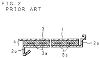
- FIG. 2 is a cross section cut along the II-II line of FIG. 1
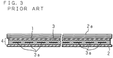
- FIG. 3 is a cross section cut along the III-III line of FIG. 1.
- numeral 2 is a sheet-like substrate formed of a steel plate, and this substrate 2 has, on its both edges, engagement sections 2a and 2b to be engaged with adjacent other solar cell modules.
- a seal layer 3 that seals several to several tens pieces of crystalline, amorphous or other type of solar cell elements 3a, which are arranged on the same plane and wired in series or in parallel, to protect them is layered on the substrate 2, and a sheet-like light transmitting member 1 formed of a tempered glass material capable of transmitting light is layered on the seal layer 3, thereby constructing a solar cell module.
- the seal layer 3 is formed of a synthetic resin such as PVB (polyvinyl butyral) and EVA (ethylene vinyl acetate).
- the area of the substrate 2 is larger than the area of a layered body 4 constituted by layering the light transmitting member 1 and the seal layer 3.
- the engagement section 2a on one edge of the substrate 2 is formed by bending one edge of the substrate 2 upward and further bending it in a shape corresponding to an engagement section of an adjacent solar cell module, not shown, for example, in the shape of a square bracket with its opening facing the center side.
- the engagement section 2b on the other edge of the substrate 2 is formed by bending the other edge of the substrate 2 downward and further bending it in a shape corresponding to an engagement section of other adjacent solar cell module, not shown, for example, by bending it in the direction of the substrate 2 to form an L shape.
- a plurality of solar cell modules are first arranged in a line in a girder direction on the eave side of the roof so that the engagement sections 2b are located on the eave side and then a plurality of solar cell modules are arranged in a line in a girder direction on the ridge side of the previously arranged solar cell modules so that their engagement sections 2b engage with the engagement sections 2a of the previously arranged solar cell modules, and solar cell modules are sequentially installed in the direction of the ridge.
- the edges, in the girder direction, of the solar cell modules installed in such a manner are provided with a decorative cover for preventing infiltration of rainwater and for improving the external appearance.
- the conventional solar cell module does not have sufficient water-tightness and suffers from the disadvantage of a lowering of reliability of the solar cell module due to moisture infiltration from the end of the boundary between the light transmitting member 1 or the substrate 2 and the seal layer 3 and separation of the light transmitting member 1 or the substrate 2 and the seal layer 3.
- the direction from the engagement section 2a to the engagement section 2b corresponds to the water running direction, and therefore, if there is a void between the engagement section 2a and an end face of the layered body 4, water is likely to stay in the void, resulting in a problem of facilitating moisture infiltration.
- An object of the present invention is to provide a highly reliable solar cell module by covering at least a part of end faces of a light transmitting member with a synthetic resin constituting a seal layer so as to waterproof the boundary between the light transmitting member and the seal layer, increase the contact surface between the light transmitting member and the seal layer, and prevent separation therebetween.
- Another object of the present invention is to provide a solar cell module by waterproofing the solar cell module with the use of a synthetic resin constituting the seal layer so as to prevent water infiltration at low costs without additionally preparing a waterproof agent.
- Still another object of the present invention is to provide a highly reliable solar cell module by filling the voids between raised sections formed at edges of the substrate and the end faces of the light transmitting member with a synthetic resin constituting the seal layer so as to prevent direct exposure of the boundary between the seal layer and the substrate to moisture, prevent moisture infiltration and separation at the boundary, increase the contact surface between the seal layer and the substrate and prevent separation at the boundary therebetween.
- Yet another object of the present invention is to provide a highly reliable solar cell module by providing raised sections at edges of the substrate having engagement sections arranged in the eave-to-ridge direction so as to reduce the void between the ridge-side end face of a layered body and the substrate and prevent water from staying in the void when water runs from the ridge side to the eave side, and further prevent infiltration of moisture into the eave-side end face of the layered body due to the influence of wind.
- a further object of the present invention is to provide a highly reliable solar cell module by arranging the raised sections to have a height equal to or more than the thickness of the seal layer and filling the voids between the raised sections and the end faces of the layered body up to a height equal to or more than the thickness with a synthetic resin constituting the seal layer so as to reduce the voids between the end faces of the layered body and the substrate, prevent water from staying in the voids, prevent deformation of the seal layer formed of the synthetic resin in a transverse direction and prevent breakage of the layered body and synthetic resin.
- a solar cell module according to the first aspect of the present invention is a solar cell module constructed by sealing a plurality solar cell elements between a sheet-like substrate and a sheet-like light transmitting member, with a seal layer formed of a synthetic resin, wherein at least a part of end faces of the light transmitting member is covered with the synthetic resin constituting the seal layer.
- the first aspect by covering at least a part of the end faces of the light transmitting member with the synthetic resin constituting the seal layer, it is possible to prevent direct exposure of the boundary between the light transmitting member and the seal layer to moisture, prevent moisture infiltration, and prevent separation at the boundary. Moreover, since the contact surface between the light transmitting member and the seal layer is increased, it is possible to prevent separation at the boundary thereof. Furthermore, since waterproofing is made using the synthetic resin constituting the seal layer, there is no need to additionally prepare a waterproof agent.
- a solar cell module according to the second aspect of the present invention is based on the first aspect, wherein edges of the substrate are provided with raised sections raised toward the light transmitting member side, and voids between the raised sections and the end faces of the light transmitting member are filled with the synthetic resin.
- the second aspect by providing the raised sections at edges of the substrate and filling the voids between the raised sections and the end faces of the light transmitting member with the synthetic resin constituting the seal layer, it is possible to prevent direct exposure of the boundary between the seal layer and the substrate to moisture, prevent moisture infiltration, and prevent separation at the boundary. Moreover, it is possible to increase the contact surface between the seal layer and the substrate and prevent separation at the boundary thereof. Furthermore, it is possible to reduce the voids between the end faces of the layered body and the substrate and prevent water from staying in the voids. In addition, it is possible to prevent deformation of the seal layer formed of a synthetic resin in a transverse direction and prevent breakage of the layered body and synthetic resin.
- a solar cell module according to the third aspect of the present invention is based on the second aspect, wherein both edges of the substrate are provided with engagement sections that come into engagement with adjacent other solar cell modules, respectively, and the raised sections are formed on the edges having the engagement sections.
- the engagement sections are arranged in the eave-to-ridge direction and water runs from the ridge side to the eave side
- by providing the raised sections on the edges having the engagement sections it is possible to reduce the void between the ridge-side end face of the layered body and the substrate and prevent water from staying in the void. Furthermore, it is possible to prevent infiltration of moisture into the eave-side end face of the layered body due to the influence of wind.
- a solar cell module according to the fourth aspect of the present invention is based on the second or third aspect, wherein the raised sections have a height equal to or more than a thickness of the seal layer.
- the fourth aspect by making the height of the raised sections equal to or more than the thickness of the seal layer and filling the voids between the raised sections and the end faces of the layered body up to a height equal to or more than the thickness with the synthetic resin constituting the seal layer, it is possible to reduce the voids between the end faces of the layered body and the substrate and prevent water from staying in the voids, and also prevent deformation of the seal layer formed of the synthetic resin in a transverse direction and prevent breakage of the layered body and synthetic resin.
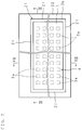
- FIG. 4 is a light-incident side plan view showing the structure of a solar cell module according to the first embodiment of the present invention
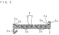
- FIG. 5 is a cross section cut along the V-V line of FIG. 4
- FIG. 6 is a cross section cut along the VI-VI line of FIG. 4.
- numeral 2 is a sheet-like substrate formed of a steel plate, and this substrate 2 is rectangular when seen in the plan view and has engagement sections 2a and 2b to be engaged with adjacent other solar cell modules on both edges.
- a seal layer 3 that seals several to several tens pieces of crystalline, amorphous or other type of solar cell elements 3a, which are arranged on the same plane and wired in series or in parallel, with a synthetic resin 3b formed of a synthetic resin such as PVB and EVA to protect them is layered on the substrate 2, and a sheet-like light transmitting member 1 formed of a tempered glass material capable of transmitting light is layered on the seal layer 3, thereby constructing a solar cell module.
- the area of the substrate 2 is larger than the area of the bottom face of a layered body 4 constituted by layering the light transmitting member 1 and the seal layer 3.
- the engagement section 2a on one edge of the substrate 2 is formed in an inverted L shape by designing the one edge of the substrate 2 to have a raised section 2d raised perpendicularly from the substrate 2 and a section located above the layered body 4.
- the raised section 2d is arranged to have a height so as not to cause at least the engagement section 2a to come into contact with the light transmitting member 1.
- the engagement section 2b on the other edge of the substrate 2 is formed on the other edge of the substrate 2, and has a suspended portion hanged perpendicularly from the substrate 2 and an L-shaped portion with an end facing the center side.
- the substrate 2 has a raised section 2c raised perpendicularly from the substrate 2, on the top face of the other edge having the engagement section 2b.
- the substrate 2 has also the raised sections 2c on the top faces of two edges other than the edges having the engagement sections 2a and 2b.
- the raised sections 2c are arranged to have a height exceeding the thickness of the layered body 4.
- the amount of the synthetic resin 3b constituting the seal layer 3 is not less than an amount necessary for sufficiently constructing the layered body 4, and voids formed between the layered body 4 and the raised sections 2d, 2c are filled with an excess of the synthetic resin 3b, so that the end faces of the light transmitting member 1 are covered with the synthetic resin 3b.
- the solar cell module of the present invention by filling the void between the engagement section 2a and the end face of the layered body 4, where water is most likely to stay, with the synthetic resin 3b, it is possible to prevent water from staying in the void. Moreover, by filling the void between the raised section 2c on the engagement section 2b side and the layered body 4, with the synthetic resin 3b, it is possible to waterproof the end face of the layered body 4 on the engagement section 2b side which is most easily influenced by wind and rain, prevent infiltration of water into the boundary between the seal layer 3 and the substrate 2 or the light transmitting member 1 and avoid separation at the boundary. Besides, since waterproofing is made using the synthetic resin 3b, there is no need to additionally prepare a waterproof agent. Furthermore, since the raised sections 2c, 2c, 2c or the raised section 2d are arranged to have a height higher the thickness of the seal layer 3, they also perform the function of preventing deformation of the seal layer 3 in a transverse direction.
- the raised sections 2c, 2c, 2c are arranged to have a height equal to or more than the thickness of the layered body 4 so as to increase the contact surface with the synthetic resin 3b, but, if they are arranged to have a height lower than the thickness of the layered body 4, they are arranged to have at least a height higher than the position of the bottom face of the light transmitting member 1 so as to prevent deformation of the seal layer 3 in a transverse direction.
- a solar cell device is constructed by installing a plurality of solar cell modules having such a structure in a connected manner from the eave side to the ridge side, for example, so that the engagement section 2a of one of adjacent solar cell modules engages with the engagement section 2b of the other solar cell module.
- the solar cell module of the first embodiment of the present invention and the conventional solar cell module were subjected to a moisture resistance test according to JIS C 8917.
- This moisture resistance test was carried out by leaving the respective solar cell modules in the conditions of a temperature of 85 ⁇ 2°C and a humidity of 90 to 93 ⁇ 5% continuously for 1000 ⁇ 12 hours and 2000 ⁇ 12 hours. Further, parameters (maximum power Pmax, open circuit voltage Voc, short-circuit current Isc, fill factor F.F.) were measured before and after the test, and the rate of change of these parameters (the percentage of the characteristic before the test/the characteristic after the test) (%) was calculated.
- the conventional solar cell module maintained its characteristics when it was left in high-temperature and high-humidity environment for around 1000 hours as the JIS standard, but its characteristics were considerably lowered when it was left in high-temperature and high-humidity environment for around 2000 hours.
- the solar cell module of the present invention retained its initial characteristics even when it was left in high-temperature and high-humidity environment for around 2000 hours, and kept the reliability over the long time.
- the second embodiment explains a solar cell module having no engagement section.
- FIG. 7 is a light-incident side plan view showing the structure of a solar cell module according to the second embodiment of the present invention
- FIG. 8 is a cross section cut along the VIII-VIII line of FIG. 7
- FIG. 9 is a cross section cut along the IX-IX line of FIG. 7.
- numeral 20 is a substrate in the form of a flat plate, and a recessed section 21 which is rectangular when seen in the plan view is formed in the center by raised sections 2f, 2f, ... formed on the top faces of the four edges of the substrate 2.
- a seal layer 3 that seals several to several tens pieces of crystalline, amorphous or other type of solar cell elements 3a, which are arranged on the same plane and wired in series or in parallel, with a synthetic resin 3b formed of a synthetic resin such as PVB and EVA to protect them is layered on a bottom face portion 2e of the recessed section 21, and the light transmitting member 1 is layered on the seal layer 3, thereby constructing a solar cell module.
- the area of the bottom face portion 2e is larger than the area of the bottom face of a layered body 4 constituted by layering the light transmitting member 1 and the seal layer 3, and the four peripheral raised sections 2f, 2f, ... are raised perpendicularly from the bottom face portion 2e.
- the recessed section 21 is designed deeper than the thickness of the seal layer 3, but shallower than the thickness of the layered body 4.
- the amount of the synthetic resin 3b constituting the seal layer 3 is not less than an amount necessary for sufficiently constructing the layered body 4, and voids between the layered body 4 and the raised sections 2f, 2f, ... are filled with an excess of the synthetic resin 3b, so that the end faces of the light transmitting member 1 are covered with the synthetic resin 3b.
- the solar cell module of the present invention since the end faces of the layered body 4 are covered with the synthetic resin 3b, it is possible to prevent infiltration of water into the boundary between the seal layer 3 and the substrate 20 or the light transmitting member 1 and avoid separation at the boundary. Furthermore, since waterproofing is made using the synthetic resin 3b, it is not necessary to additionally prepare a waterproof agent. In addition, the raised sections 2f, 2f, ... also perform the function of preventing deformation of the seal layer 3 in a transverse direction.
- a tempered glass material in the form of a sheet is used as the light transmitting material in the first and second embodiments, it is also possible to use a plastic film
- the present invention is not necessarily limited to such a solar cell module, and, needless to say, the present invention is also applicable to an integrated type amorphous solar cell module produced by directly forming a plurality of solar cell elements using an amorphous semiconductor adhered onto the light transmitting member serving as the substrate.
- reference signs those reference signs have been included for the sole purpose of increasing the intelligibility of the claims and accordingly. such reference signs do not have any limiting effect on the scope of each element identified by way of example by such reference signs.
Landscapes
- Engineering & Computer Science (AREA)
- Architecture (AREA)
- Civil Engineering (AREA)
- Structural Engineering (AREA)
- Photovoltaic Devices (AREA)
Applications Claiming Priority (2)
| Application Number | Priority Date | Filing Date | Title |
|---|---|---|---|
| JP2000275523A JP3594540B2 (ja) | 2000-09-11 | 2000-09-11 | 太陽電池モジュール |
| JP2000275523 | 2000-09-11 |
Publications (2)
| Publication Number | Publication Date |
|---|---|
| EP1187222A2 true EP1187222A2 (fr) | 2002-03-13 |
| EP1187222A3 EP1187222A3 (fr) | 2004-01-14 |
Family
ID=18761133
Family Applications (1)
| Application Number | Title | Priority Date | Filing Date |
|---|---|---|---|
| EP01120776A Withdrawn EP1187222A3 (fr) | 2000-09-11 | 2001-09-07 | Module de cellules solaires |
Country Status (3)
| Country | Link |
|---|---|
| US (1) | US6552258B2 (fr) |
| EP (1) | EP1187222A3 (fr) |
| JP (1) | JP3594540B2 (fr) |
Families Citing this family (71)
| Publication number | Priority date | Publication date | Assignee | Title |
|---|---|---|---|---|
| EP1172863A3 (fr) * | 2000-07-10 | 2007-02-14 | Sanyo Electric Co., Ltd. | Procédé pour installer des modules de cellules solaires et module de cellules solaires |
| US20040154655A1 (en) * | 2003-02-12 | 2004-08-12 | Sharp Kabushiki Kaisha | Attaching structural unit used for installing quadrangular solar-battery module onto slanted roof |
| US20080283115A1 (en) * | 2004-01-28 | 2008-11-20 | Yuko Fukawa | Solar Battery Module and Photovoltaic Generation Device |
| US7297866B2 (en) * | 2004-03-15 | 2007-11-20 | Sunpower Corporation | Ventilated photovoltaic module frame |
| WO2008136872A2 (fr) * | 2006-12-22 | 2008-11-13 | Adriani Paul M | Structures de modules solaires fiables et peu coûteux |
| US8205400B2 (en) * | 2007-02-08 | 2012-06-26 | Luma Resources, Llc | Solar panel roof kit |
| FR2914785B1 (fr) * | 2007-04-06 | 2009-05-15 | Saint Gobain Ct Recherches | Revetement de toiture photovoltaique |
| WO2009032862A2 (fr) * | 2007-09-03 | 2009-03-12 | Robert Stancel | Système de montage pour des modules solaires |
| US20100065105A1 (en) * | 2008-09-12 | 2010-03-18 | Francois Andre Koran | Thin Film Photovoltaic Module Having a Contoured Substrate |
| US8124868B2 (en) * | 2008-12-16 | 2012-02-28 | Solutia Inc. | Thin film photovoltaic module with contoured deairing substrate |
| JP2010251667A (ja) * | 2009-04-20 | 2010-11-04 | Sanyo Electric Co Ltd | 太陽電池 |
| USD677619S1 (en) * | 2011-09-16 | 2013-03-12 | EchoFirst, Inc. | Solar module assembly |
| CA2828862A1 (fr) | 2012-10-01 | 2014-04-01 | Building Materials Investment Corporation | Systeme de panneau solaire de toit avec traitements de bordure et de surface |
| CA3159500A1 (fr) | 2019-11-27 | 2021-06-03 | William Sirski | Module photovoltaique integre a un toit ayant un element d'espacement |
| US11398795B2 (en) | 2019-12-20 | 2022-07-26 | GAF Energy LLC | Roof integrated photovoltaic system |
| MX2022009069A (es) | 2020-01-22 | 2023-01-05 | GAF Energy LLC | Tejas para techos fotovoltaicas integradas, métodos, sistemas y kits de las mismas. |
| US11961928B2 (en) | 2020-02-27 | 2024-04-16 | GAF Energy LLC | Photovoltaic module with light-scattering encapsulant providing shingle-mimicking appearance |
| CA3174671A1 (fr) | 2020-04-09 | 2021-10-14 | GAF Energy LLC | Module photovoltaique stratifie tridimensionnel |
| MX2022013519A (es) | 2020-04-30 | 2022-11-16 | GAF Energy LLC | Hoja frontal y hoja trasera de modulo fotovoltaico. |
| WO2021230938A1 (fr) | 2020-05-13 | 2021-11-18 | GAF Energy LLC | Passe-câble électrique |
| CN115769383A (zh) | 2020-06-04 | 2023-03-07 | Gaf能源有限责任公司 | 光伏屋顶板及其安装方法 |
| MX2023000952A (es) | 2020-07-22 | 2023-04-19 | GAF Energy LLC | Modulos fotovoltaicos. |
| MX2023001822A (es) | 2020-08-11 | 2023-05-08 | GAF Energy LLC | Sistema fotovoltaico montado en el techo y método para la transferencia inalámbrica de energía eléctrica. |
| MX2023002696A (es) | 2020-09-03 | 2023-05-24 | GAF Energy LLC | Sistema fotovoltaico integrado en edificios. |
| USD950482S1 (en) | 2020-10-02 | 2022-05-03 | GAF Energy LLC | Solar roofing system |
| USD950481S1 (en) | 2020-10-02 | 2022-05-03 | GAF Energy LLC | Solar roofing system |
| US11545928B2 (en) | 2020-10-13 | 2023-01-03 | GAF Energy LLC | Solar roofing system |
| EP4229750A4 (fr) | 2020-10-14 | 2024-11-13 | Gaf Energy LLC | Appareil de montage pour modules photovoltaïques |
| US11454027B2 (en) | 2020-10-29 | 2022-09-27 | GAF Energy LLC | System of roofing and photovoltaic shingles and methods of installing same |
| CA3197587A1 (fr) | 2020-11-12 | 2022-05-19 | Gabriela Bunea | Bardeaux de toiture a poignees |
| WO2022103841A1 (fr) | 2020-11-13 | 2022-05-19 | GAF Energy LLC | Systèmes et procédés pour modules photovoltaïques |
| US11996797B2 (en) | 2020-12-02 | 2024-05-28 | GAF Energy LLC | Step flaps for photovoltaic and roofing shingles |
| US11459757B2 (en) | 2021-01-19 | 2022-10-04 | GAF Energy LLC | Watershedding features for roofing shingles |
| WO2022178311A1 (fr) | 2021-02-19 | 2022-08-25 | GAF Energy LLC | Module photovoltaïque pour toit avec bande continue de fibres |
| US12568694B2 (en) | 2021-03-19 | 2026-03-03 | GAF Energy LLC | Photovoltaic module with a laminated potted printed circuit board |
| WO2022212173A1 (fr) | 2021-03-29 | 2022-10-06 | GAF Energy LLC | Composants électriques pour systèmes photovoltaïques |
| US11527665B2 (en) | 2021-05-06 | 2022-12-13 | GAF Energy LLC | Photovoltaic module with transparent perimeter edges |
| MX2023014362A (es) | 2021-06-02 | 2023-12-15 | GAF Energy LLC | Modulo fotovoltaico con encapsulante de dispersion de la luz que proporciona una apariencia que imita a las tejas. |
| US12009781B2 (en) | 2021-07-06 | 2024-06-11 | GAF Energy LLC | Jumper module for photovoltaic systems |
| US11512480B1 (en) | 2021-07-16 | 2022-11-29 | GAF Energy LLC | Roof material storage bracket |
| US11728759B2 (en) | 2021-09-01 | 2023-08-15 | GAF Energy LLC | Photovoltaic modules for commercial roofing |
| WO2023141566A1 (fr) | 2022-01-20 | 2023-07-27 | GAF Energy LLC | Bardeaux de toiture pour imiter l'aspect de modules photovoltaïques |
| CA3188772A1 (fr) | 2022-02-08 | 2023-08-08 | GAF Energy LLC | Systeme photovoltaique integre au batiment |
| WO2023164494A1 (fr) | 2022-02-23 | 2023-08-31 | GAF Energy LLC | Bardeau de toiture et son procédé de fabrication |
| WO2023173019A1 (fr) | 2022-03-10 | 2023-09-14 | GAF Energy LLC | Encapsulant et feuille arrière combinés pour modules photovoltaïques |
| WO2023197010A1 (fr) | 2022-04-08 | 2023-10-12 | GAF Energy LLC | Connecteur à profil bas pour systèmes de toiture solaire |
| CA3257758A1 (fr) | 2022-06-06 | 2023-12-14 | GAF Energy LLC | Indicateurs de composants actifs pour systèmes photovoltaïques |
| WO2024015996A1 (fr) | 2022-07-15 | 2024-01-18 | GAF Energy LLC | Système de toiture solaire avec bardeaux de toiture composites en fibres |
| CA3264095A1 (fr) | 2022-08-24 | 2024-02-29 | GAF Energy LLC | Système de formation d'une membrane de toiture et procédé associé |
| EP4581684A1 (fr) | 2022-08-29 | 2025-07-09 | Gaf Energy LLC | Modules photovoltaïques à couches décalées |
| US12034089B2 (en) | 2022-09-01 | 2024-07-09 | GAF Energy LLC | Anti-reflective photovoltaic shingles and related methods |
| WO2024059462A1 (fr) | 2022-09-13 | 2024-03-21 | GAF Energy LLC | Système de toiture à capteurs et procédé associé |
| WO2024073288A1 (fr) | 2022-09-26 | 2024-04-04 | GAF Energy LLC | Modules photovoltaïques intégrés avec un parement et une clôture de bâtiment |
| US12143064B2 (en) | 2022-09-29 | 2024-11-12 | GAF Energy LLC | Jumper module with sleeve |
| WO2024091828A1 (fr) | 2022-10-25 | 2024-05-02 | GAF Energy LLC | Matériaux de toiture et procédés associés |
| US12231075B2 (en) | 2022-10-27 | 2025-02-18 | GAF Energy LLC | Building integrated photovoltaic systems |
| US12413183B2 (en) | 2022-11-15 | 2025-09-09 | GAF Energy LLC | Electrical cable passthrough for photovoltaic systems |
| US11811361B1 (en) | 2022-12-14 | 2023-11-07 | GAF Energy LLC | Rapid shutdown device for photovoltaic modules |
| US12355390B1 (en) | 2023-02-03 | 2025-07-08 | GAF Energy LLC | Solar shingle and associated roofing system and method |
| US12445089B2 (en) | 2023-02-03 | 2025-10-14 | GAF Energy LLC | Photovoltaic module, and associated kit, system, and method |
| US12413174B2 (en) | 2023-02-21 | 2025-09-09 | GAF Energy LLC | Roofing system including photovoltaic module wireway cover, and associated method |
| US12176849B2 (en) | 2023-02-23 | 2024-12-24 | GAF Energy LLC | Photovoltaic shingles with multi-module power electronics |
| US12506440B2 (en) | 2023-02-28 | 2025-12-23 | GAF Energy LLC | Photovoltaic modules with energy storage components |
| CA3231973A1 (en) | 2023-03-14 | 2025-06-26 | GAF Energy LLC | Integrated cell and circuit interconnection |
| US12009782B1 (en) | 2023-04-04 | 2024-06-11 | GAF Energy LLC | Photovoltaic systems with wireways |
| US12413177B2 (en) | 2023-08-31 | 2025-09-09 | GAF Energy LLC | Photovoltaic modules and roofing shingles with nail zones |
| US12451838B1 (en) | 2023-10-06 | 2025-10-21 | GAF Energy LLC | Failsafe functionality for photovoltaic modules |
| WO2025090902A1 (fr) | 2023-10-26 | 2025-05-01 | GAF Energy LLC | Systèmes de toiture à protection contre l'entrée d'eau |
| WO2025122742A1 (fr) | 2023-12-05 | 2025-06-12 | GAF Energy LLC | Système de toiture pour la prévention de la déformation d'un bardeau de toiture |
| WO2025217150A1 (fr) | 2024-04-10 | 2025-10-16 | GAF Energy LLC | Bardeaux de toiture à structure ignifuge |
| US12540474B2 (en) | 2024-07-22 | 2026-02-03 | GAF Energy LLC | Electrically grounding metal roofing shingles with photovoltaic systems |
Family Cites Families (11)
| Publication number | Priority date | Publication date | Assignee | Title |
|---|---|---|---|---|
| GB2278618B (en) * | 1993-05-20 | 1996-06-19 | Univ Southampton | A tile |
| US5733382A (en) * | 1995-12-18 | 1998-03-31 | Hanoka; Jack I. | Solar cell modules and method of making same |
| US5986203A (en) * | 1996-06-27 | 1999-11-16 | Evergreen Solar, Inc. | Solar cell roof tile and method of forming same |
| US5741370A (en) * | 1996-06-27 | 1998-04-21 | Evergreen Solar, Inc. | Solar cell modules with improved backskin and methods for forming same |
| JPH1072910A (ja) * | 1996-08-30 | 1998-03-17 | Canon Inc | 横葺き屋根板、屋根材一体型太陽電池、横葺き屋根用継ぎ手及び横葺き屋根の施工方法 |
| JP3825843B2 (ja) * | 1996-09-12 | 2006-09-27 | キヤノン株式会社 | 太陽電池モジュール |
| JPH10233521A (ja) * | 1997-02-19 | 1998-09-02 | Canon Inc | 太陽電池モジュール、及びそれを用いた太陽電池一体型建材、太陽光発電装置 |
| EP1020930A3 (fr) * | 1999-01-14 | 2007-03-14 | Canon Kabushiki Kaisha | Module de cellules solaires et dispositif de production d'énergie |
| AU2233900A (en) * | 1999-03-23 | 2000-09-28 | Kaneka Corporation | Photovoltaic module |
| AU764832B2 (en) * | 1999-05-31 | 2003-09-04 | Kaneka Corporation | Solar battery module |
| AU5400501A (en) * | 2000-06-27 | 2002-01-03 | Canon Kabushiki Kaisha | Photovoltaic element, producing method therefor, and solar cell modules |
-
2000
- 2000-09-11 JP JP2000275523A patent/JP3594540B2/ja not_active Expired - Fee Related
-
2001
- 2001-09-07 EP EP01120776A patent/EP1187222A3/fr not_active Withdrawn
- 2001-09-07 US US09/948,351 patent/US6552258B2/en not_active Expired - Fee Related
Also Published As
| Publication number | Publication date |
|---|---|
| JP2002094084A (ja) | 2002-03-29 |
| US20020053360A1 (en) | 2002-05-09 |
| EP1187222A3 (fr) | 2004-01-14 |
| JP3594540B2 (ja) | 2004-12-02 |
| US6552258B2 (en) | 2003-04-22 |
Similar Documents
| Publication | Publication Date | Title |
|---|---|---|
| EP1187222A2 (fr) | Module de cellules solaires | |
| US11626829B2 (en) | Methods of manufacturing and installing a solar roof tile assembly | |
| US5437735A (en) | Photovoltaic shingle system | |
| US5575861A (en) | Photovoltaic shingle system | |
| US10778139B2 (en) | Building integrated photovoltaic system with glass photovoltaic tiles | |
| US9786802B2 (en) | Photovoltaic roofing panels, photovoltaic roofing assemblies, and roofs using them | |
| US8656657B2 (en) | Photovoltaic roofing elements | |
| KR101188647B1 (ko) | 개량된 태양광 장치 및 방법 | |
| US20140150843A1 (en) | Shingle-like photovoltaic modules | |
| US20140174508A1 (en) | Solar module | |
| CN106464200B (zh) | 太阳能电池模块及屋顶结构 | |
| US20160105145A1 (en) | System and Method for Transparent Solar Panels | |
| KR20120140250A (ko) | 개선된 광전 디바이스 | |
| GB2583388A (en) | Photovoltaic roof covering and method of manufacture | |
| US20140318603A1 (en) | All Plastic Solar Panel | |
| KR20250111259A (ko) | 고내구성 및 고경량의 슁글드 태양광 모듈 구조 및 제조 방법 | |
| JP2000164912A (ja) | 太陽電池モジュール及びその製造方法 | |
| GB2517914A (en) | Improved Solar Roof Tile | |
| JP2014152513A (ja) | 太陽電池一体屋根葺材 | |
| JPH0864853A (ja) | 太陽光発電屋根 | |
| JPH0666041U (ja) | 太陽電池モジュール | |
| JPH0888390A (ja) | 太陽電池モジュール |
Legal Events
| Date | Code | Title | Description |
|---|---|---|---|
| PUAI | Public reference made under article 153(3) epc to a published international application that has entered the european phase |
Free format text: ORIGINAL CODE: 0009012 |
|
| AK | Designated contracting states |
Kind code of ref document: A2 Designated state(s): AT BE CH CY DE DK ES FI FR GB GR IE IT LI LU MC NL PT SE TR |
|
| AX | Request for extension of the european patent |
Free format text: AL;LT;LV;MK;RO;SI |
|
| PUAL | Search report despatched |
Free format text: ORIGINAL CODE: 0009013 |
|
| AK | Designated contracting states |
Kind code of ref document: A3 Designated state(s): AT BE CH CY DE DK ES FI FR GB GR IE IT LI LU MC NL PT SE TR |
|
| AX | Request for extension of the european patent |
Extension state: AL LT LV MK RO SI |
|
| 17P | Request for examination filed |
Effective date: 20040506 |
|
| AKX | Designation fees paid |
Designated state(s): DE GB IT |
|
| 17Q | First examination report despatched |
Effective date: 20041228 |
|
| STAA | Information on the status of an ep patent application or granted ep patent |
Free format text: STATUS: THE APPLICATION IS DEEMED TO BE WITHDRAWN |
|
| 18D | Application deemed to be withdrawn |
Effective date: 20150401 |