EP1187272A2 - Structure de fiche de connexion pour câble de haute tension - Google Patents
Structure de fiche de connexion pour câble de haute tension Download PDFInfo
- Publication number
- EP1187272A2 EP1187272A2 EP01402285A EP01402285A EP1187272A2 EP 1187272 A2 EP1187272 A2 EP 1187272A2 EP 01402285 A EP01402285 A EP 01402285A EP 01402285 A EP01402285 A EP 01402285A EP 1187272 A2 EP1187272 A2 EP 1187272A2
- Authority
- EP
- European Patent Office
- Prior art keywords
- plug
- fitting body
- terminal
- enclosure
- boot
- Prior art date
- Legal status (The legal status is an assumption and is not a legal conclusion. Google has not performed a legal analysis and makes no representation as to the accuracy of the status listed.)
- Withdrawn
Links
Images


Classifications
-
- H—ELECTRICITY
- H01—ELECTRIC ELEMENTS
- H01R—ELECTRICALLY-CONDUCTIVE CONNECTIONS; STRUCTURAL ASSOCIATIONS OF A PLURALITY OF MUTUALLY-INSULATED ELECTRICAL CONNECTING ELEMENTS; COUPLING DEVICES; CURRENT COLLECTORS
- H01R24/00—Two-part coupling devices, or either of their cooperating parts, characterised by their overall structure
- H01R24/20—Coupling parts carrying sockets, clips or analogous contacts and secured only to wire or cable
-
- H—ELECTRICITY
- H01—ELECTRIC ELEMENTS
- H01R—ELECTRICALLY-CONDUCTIVE CONNECTIONS; STRUCTURAL ASSOCIATIONS OF A PLURALITY OF MUTUALLY-INSULATED ELECTRICAL CONNECTING ELEMENTS; COUPLING DEVICES; CURRENT COLLECTORS
- H01R2101/00—One pole
Definitions
- the present invention generally relates to a plug-side connector structure for a high-voltage electrical cable.
- the latter connects an ignition coil to a spark plug for an internal-combustion engine of a vehicle e.g. automobile.
- Fig. 1 shows such a plug-side connector structure known in the prior art.
- a high-voltage terminal structure 102 is mounted at an end portion of a high-voltage cable 101.
- a spark plug P is provided with a terminal tip Pt and a glass or ceramic portion Pg (generically designated hereafter by the term "glass portion”.
- the high-voltage terminal structure 102 and the terminal tip Pt and glass portion Pg of the spark plug are contained in a boot or shroud 105 made of e.g. rubber.
- the high-voltage terminal structure 102 and peripheral devices are thus electrically insulated, and an electrical current is prevented from leaking out along the glass portion surface of the spark plug P.
- the high-voltage terminal structure 102 of the high-voltage cable 101 is first inserted into the boot 105 from one of its sides.
- the terminal tip Pt and glass portion Pg of the spark plug P are then inserted into the boot 105 from the opposite side, so that the terminal tip Pt is fitted into the high-voltage terminal structure 102 inside the boot 105.
- the boot 105 is formed of an elastic material e.g. rubber, it lacks rigidity.
- its remaining portion tends to be insufficiently rigid.
- the terminal tip Pt and glass portion Pg may then be moved into the boot 105 diagonally (Fig.2), whereupon the terminal tip Pt may abut against the open edge of the high-voltage terminal structure 102. Matching of the two connection edges thus becomes difficult. Further, when the terminal tip Pt is forcibly inserted, the high-voltage terminal structure 102 itself may be deformed.
- the high-voltage terminal structure 102 and the terminal tip Pt When the deformed high-voltage terminal structure is repeatedly used, the high-voltage terminal structure 102 and the terminal tip Pt will be partially worn out, and the conductivity between them will deteriorate. As a result, the internal-combustion engine can fail to fire or stall.
- An object of the invention is therefore to provide a plug-side connector structure, in which the terminal tip of the spark plug can be smoothly inserted into, and connected to, the high-voltage terminal structure.
- a plug-side connector structure for a high-voltage cable comprising a boot, the boot having a substantially cylindrical form with first and second ends and containing a high-voltage terminal structure attached to an end of the high-voltage cable which extends outwardly through the first end of the boot.
- the boot is adapted to receive, through the second end thereof, a terminal tip and a subsequent glass or ceramic portion of a spark plug such that the terminal tip can be fitted into the high-voltage terminal structure.
- the boot comprises a terminal enclosure for containing the high-voltage terminal structure, and a glass- or ceramic-portion enclosure adapted to contain the glass or ceramic portion and located adjacent the second end of the boot.
- the high-voltage terminal structure comprises a cable connector system connected to the one end of the high-voltage cable, and a plug-fit system.
- the plug-fit system includes a fitting body having a cylindrical form and adapted to receive the terminal tip.
- the plug-fit system further includes a guiding means for guiding the terminal tip into the fitting body.
- the guiding means comprises a tapered guide extending from the fitting body towards the second end of the boot while enlarging in the radial direction of the fitting body so as to form a flared end.
- the flared end of the tapered guide has an outermost external diameter greater than the internal diameter of the glass- or ceramic-portion enclosure.
- the glass portion enclosure and the terminal enclosure respectively include an internal circular face, between which is provided a circular recess, such that, when the high-voltage terminal structure is contained in the terminal enclosure, the tapered guide is fitted into the circular recess.
- the cylindrical form of the fitting body has a given external diameter, such that the outermost external diameter of the tapered guide is about 1.4 to about 1.6 times greater than the external diameter of the fitting body.
- the cylindrical form of the fitting body has a longitudinally extending surface line
- the tapered guide has an external taper angle which is defined relative to the longitudinally extending surface line of the fitting body, such that the external taper angle of the tapered guide ranges between about 120° and about 150°.
- the tapered guide may be composed of a plurality of fins separated from one another in the circumferential direction of the tapered guide, and comprise a slit flared end equivalent to the flared end having the outermost external diameter described above.
- the above guiding means comprises a tapered guide extending from the fitting body towards the second end of the boot while enlarging in the radial direction of the fitting body so as to form a flared end.
- the flared end has an outermost external diameter substantially the same as the internal diameter of the glass- or ceramic-portion enclosure, such that, when the high-voltage terminal structure is contained in the terminal enclosure, the circular edge is hermetically attached to the internal circular face of the glass- or ceramic-portion enclosure.
- the guiding means comprises a cylindrical guide having a common cylinder axis with the fitting body, the cylindrical guide being fitted around the fitting body.
- the cylindrical guide is then extendable from the fitting body along the common cylinder axis so as to be contained in the glass- or ceramic-portion enclosure, and retractable such that, when the terminal tip and glass or ceramic portion are inserted into the boot, the cylindrical guide can be pushed into the boot by the glass or ceramic portion and the terminal tip can be led into the fitting body, whereby the high-voltage terminal structure is held in the terminal enclosure.
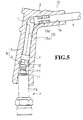
- the plug-side connector structure for high-voltage cable comprises a high-voltage terminal structure 1 attached to an end portion of a high-voltage cable K drawn out from e.g. an ignition coil, and a boot 10 having a cylindrical shape containing the high-voltage terminal structure 1.
- a knob-like terminal tip Pt projects from a spark plug P provided at the side of an internal-combustion engine.
- This terminal tip Pt together with a glass or ceramic portion (hereafter referred to generically as a glass portion) Pg extending therefrom, is inserted into the boot 10 from the side opposite the ignition coil, and connected to the high-voltage terminal structure 1 inside the boot 10.
- the high-voltage terminal structure 1 is stamped and transformed from a metal sheet.
- a cable connector system 2 is attached to an end portion of the high-voltage cable K, and a plug-fit system 5 is adapted to fit to the terminal tip Pt of the spark plug P.
- the cable connector system 2 and the plug-fit system 5 have a substantially inverted "L" configuration.
- the cable connector system 2 is configured so as to fasten the end portion of the high-voltage cable K by clamping or crimping.
- the end portion of the high-voltage cable K is initially stripped of its coating to expose the cable's core wire.
- the bared core wire is folded back over a portion of the length of the coating.
- the whole cable-end structure is then clamped or crimped by the cable connector system, so that the core wire of the high-voltage cable K is connected to the high-voltage terminal structure 1.
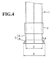
- the plug-fit system 5 comprises a tubular fitting body 6 into which the terminal tip Pt can be inserted, and a tapered guide 8 formed at the opening (bottom end in Fig.3) of the fitting body 6.
- the fitting body 6 is formed by rounding a metal sheet, and has a substantially tubular shape, the inner diameter of the tube being arranged to press-fit with the terminal tip Pt.
- the terminal tip Pt can be electrically connected to the high-voltage terminal structure 1 by press-fitting the terminal tip Pt into the fitting body 6 through the tapered guide 8.
- the fitting body 6 is wrapped with a substantially C-shaped elastic ring 7 which prevents the body from swelling and to make connections between the fitting body 6 and the terminal tip Pt more reliable.
- the tapered guide 8 is formed as an extension of the fitting body 6, and enlarges towards its open end (downwards in Figs.3 and 4).
- the outermost end of the tapered guide 8 has an external diameter A, which is larger than the diameter of a glass-portion (or ceramic-portion) enclosure 11 (described infra).
- the boot 10 is made of an elastic insulator material such as rubber. It is formed into an inverted L shaped cylindrical form.
- the boot 10 includes the glass-portion enclosure 11 extending inwardly from one of its ends (hereafter designated second end), through which the glass portion Pg is passed. It further includes a draw-out path 14 which extends substantially horizontally (as viewed in Fig.3), from the elbow portion of the L-shaped boot 10 towards its other (first) end. The portion between the glass-portion enclosure 11 and the draw-out path 14 forms a terminal enclosure 13 adapted to contain the high-voltage terminal structure 1.
- the glass-portion enclosure 11 has an internal face whose shape is made to correspond to the external face shape of the glass portion Pg, so that the latter can be contained hermetically therein. In this manner, electrical current is prevented from leaking out along the glass portion surface.
- the terminal enclosure 13 comprises an inverted L-shaped hole, corresponding to the shape of the high-voltage terminal structure 1.
- the terminal enclosure 13 comprises a plug-fit system enclosure 13a, which is located below the elbow portion and adapted to contain the fitting body 6 in the plug-fit system 5 of the high-voltage terminal structure 1.
- the terminal container hole 13 further comprises a cable connector system enclosure 13b, which extends horizontally from the elbow portion and is adapted to contain the cable connector system 2 of the high-voltage terminal structure 1. Accordingly, the high-voltage terminal structure 1 is arranged in the boot 10 by press-fitting it into the terminal enclosure 13.
- the plug-fit system enclosure 13a has an internal diameter (e.g. 7.2 mm) substantially corresponding to, or slightly smaller than, the external diameter of the fitting body 6 of the plug-fit system 5.
- the fitting body 6 can be held at a predetermined position.
- the internal diameter of the plug-fit system enclosure 13a is made slightly larger than the remaining part, taking account of the larger diameter of the ring 7.
- the internal face of the boot 10, located between the glass-portion enclosure 11 and the terminal enclosure 13, is provided with a circular recess 12.
- the latter has a hole diameter larger than the external diameter A of the outermost edge of the tapered guide 8, so that the tapered guide 8 of the high-voltage terminal structure 1 can be contained in the circular recess 12.
- the draw-out path 14 is formed in extension of the cable connector system enclosure 13b of the terminal enclosure 13.
- the high-voltage cable K connected to the cable connector 2 in the cable connector system enclosure 13b, can be drawn out through the draw-out path 14.
- the high-voltage terminal structure 1 When the plug-side connector structure is mounted, the high-voltage terminal structure 1 is first attached to one end of the high-voltage cable K. The other end of the high-voltage cable K is then inserted into the boot 10 from below (i.e. from the second end of the boot). It passes through the glass-portion enclosure 11 and the terminal enclosure 13, and is drawn out from the draw-out path 14. By elastically deforming the boot 10, the high-voltage terminal structure 1 is pushed deeply into the boot 10, and the tapered guide 8 is fitted into the circular recess 12, whereby the high-voltage terminal structure 1 is snugly fitted into the terminal enclosure 13.
- the plug-side connector structure for the high-voltage cable K is then connected to the spark plug P as described below.
- the terminal tip Pt and glass portion Pg of the spark plug P installed in an internal-combustion engine, are inserted into the boot 10 from its second end.
- the terminal tip Pt then passes through the glass-portion enclosure 11 and fits into the plug-fit system 5, and the glass portion Pg fits into the glass-portion enclosure 11.
- the boot 10 may be considerably distorted, and the terminal tip Pt may be inserted into the plug-fit system 5 biased or askew with respect to the high-voltage terminal structure 1.
- the terminal tip Pt abuts to the internal face of the tapered guide 8, and is guided into the fitting body 6.
- the terminal tip Pt is prevented from hooking with the opening edge of the plug-fit system 5 of the high-voltage terminal structure 1, and the terminal tip Pt and the plug-fit system 5 can be fitted together very smoothly.
- the tapered guide 8 of the high-voltage terminal structure 1 is fitted into the circular recess 12 formed at a position between the glass-portion enclosure 11 and the terminal enclosure 13.
- the outermost edge of the tapered guide 8 may have an external diameter A substantially greater than the hole diameter B of the glass-portion enclosure 11. As mentioned above, the terminal tip Pt can then be guided into the fitting body 6 very smoothly.
- the external diameter A of the outermost edge of the guide 8 is set at a value greater than, preferably at about 1.4 to about 1.6 times, the external diameter C of the fitting body 6.
- the external taper angle ⁇ of the tapered guide 8 is set at a value suitable for guiding the terminal tip into the fitting body, preferably between about 120° and about 150°.
- the high-voltage terminal structure 1 is mounted into the boot 10 less easily.
- the tapered guide 8 when the external taper angle ⁇ is greater than about 150°, the tapered guide 8 must be lengthened as a function of the external diameter A. As a result, the boot 10 must also be lengthened, lowering thus its rigidity.
- a second embodiment of the present invention is now described, in which the structure components common with those of the first embodiment are referred to with the same numerals. Only the different points from the first embodiment are specifically mentioned.
- a plug-fit system 5B of a high-voltage terminal structure 1B comprises a tapered guide 8B. Its outermost edge has an external diameter substantially the same as the internal diameter of a glass portion enclosure 11B.
- the high-voltage terminal structure 1B is held by the terminal enclosure 13B, while the circular rim of the outermost edge of the tapered guide 8B is closely placed into contact with the internal face of the glass-portion enclosure 11B.
- the fitting body 6 comprises a tapered guide 8B, as in the case of the first embodiment. Accordingly, the terminal tip Pt can be led into the plug-fit system 5 of the high-voltage terminal structure 1 as smoothly as in the case of the first embodiment.
- the internal circular face of the tapered guide 8B continuously extends from the latter. Therefore, when the plug-fit system 5B is inserted into the glass portion enclosure 11B, it is directly and securely led into the tapered guide 8B, and then into the fitting body 6. The terminal tip Pt is thus reliably guided into the plug-fit system 5 of the high-voltage terminal structure 1 by the tapered guide 8B.
- the first and second embodiments may include variant embodiments as explained below.
- the tapered guides 8 and 8B are prepared by stretching an end portion of a sheet.
- such a process can make the stretched sheet too thin, and its mechanical strength too weak.
- the stretching operation is a rather difficult operation.
- a tapered guide 8C is composed of a plurality of flared fins 8Ca (e.g. petal form), which extend from the end portion of the fitting body 6 towards its opened end while expanding outwardly in the radial direction.
- flared fins 8Ca e.g. petal form
- Such a tapered guide 8C may be prepared before or after a sheet is rounded to form a fitting body 6.
- an end portion of the sheet is cut out and bent outwardly, such as to form petal-like fins. This manufacturing method is simple and gives uniformly thick pieces.
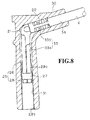
- the plug-side connector structure of the third embodiment is shown in Fig.8, in which there is provided a high-voltage cable K extending from e.g. an ignition coil, a high-voltage terminal structure 21 attached to one end of the high-voltage cable K, and a boot 30 having a substantially cylindrical form and containing the high-voltage terminal structure 21.
- a high-voltage cable K extending from e.g. an ignition coil
- a high-voltage terminal structure 21 attached to one end of the high-voltage cable K
- boot 30 having a substantially cylindrical form and containing the high-voltage terminal structure 21.
- the high-voltage terminal structure 21 is formed by stamping and bending a metal sheet (or plate).
- the structure 21 includes a cable connector system 22 fixed to an end portion of the high-voltage cable K, and a plug-fit system 25 adapted to connect to a terminal tip Pt of a spark plug P, the cable connector system 22 and the plug-fit system 25 being configured in the shape of an inverted L.
- the cable connector system 22 is fixed to the end portion of the high-voltage cable K as described for the cable connector system 2 in the first embodiment.
- the plug-fit system 25 includes a fitting body 26, into which a terminal tip Pt can be inserted, and a cylindrical guide 28 fixed around the fitting body 26.
- the fitting body 26 is formed by rounding a metal sheet into a substantially cylindrical shape.
- the former is electrically connected to the high-voltage terminal structure 21.
- a given position adjacent the bottom end of the fitting body 26 is provided with a C-shaped elastic ring 27. This ring is fixed around the fitting body 26 from the outside, and prevents the fitting body 26 from swelling. It also secures the contact between the fitting body 26 and the terminal tip Pt.
- the cylindrical guide 28 is also formed by rounding a metal sheet. It is fixed around the fitting body 26, such as to be able to move back and forth along its cylindrical axis with respect to the fitting body 26.
- the lower portion 28b of the cylindrical guide 28 along its length has an internal diameter greater than the external diameter of the ring 27 fixed around the fitting body 26, whilst the upper portion thereof 28a has an internal diameter which is greater than the external diameter of the fitting body 26, and smaller than the external diameter of the ring 27.
- the cylindrical guide 28 is thus installed around the fitting body 26 and moved downwardly, until the upper portion 28a having a smaller diameter comes into contact with the ring 27.
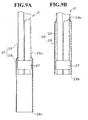
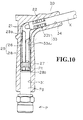
- the lower portion can freely slide up and down, such that its lowermost edge 28b extends further downwardly from the lowermost edge of the fitting body 26 ("extended position" as viewed in Figs. 8 and 9A), or both lowermost edges come to the same level (“retracted position" as viewed in Figs.9B and 10).
- spark plug P When spark plug P is inserted into the boot 30, its terminal tip Pt is fitted into the cylindrical guide 28, and its glass portion Pg comes into contact with the lowermost edge 28b of the cylindrical guide 28.
- the internal diameter of the cylindrical guide 28 is made greater than the maximum external diameter of the terminal tip Pt and smaller than the external diameter of the glass portion Pg.
- the cylindrical guide 28 is first extended downwardly (Fig.9A). The terminal tip Pt is placed into the cylindrical guide 28 from below, while the glass portion Pg comes into contact with the lowermost edge 28b of the cylindrical guide 28. Thereafter, the terminal tip Pt is inserted into the plug-fit system 25, and both are electrically connected.
- the cylindrical guide 28 is also pushed up by the terminal tip Pt by sliding. As the terminal tip Pt is already installed in the cylindrical guide 28, it is guided into towards the fitting body 26 by the sliding movement of the cylindrical guide 28. When the cylindrical guide 28 is moved upwardly up to the complete retreat point, the terminal tip Pt is inserted into the fitting body 26 and electrically connected therein.
- the boot 30 is formed of an elastic insulator material, and has a substantially inverted L shape, viewed in an elevated position.
- the boot 30 comprises, at its lower portion, a glass portion enclosure 31 for holding the glass portion Pg.
- the boot 30 further comprises a draw-out path 34 for a high-voltage cable K, which extends from the elbow portion of the boot along the horizontal portion thereof.
- a terminal enclosure 33 of the high-voltage terminal structure 21 is provided between the glass portion enclosure 31 and the draw-out path 34.
- the above glass portion enclosure 31 can contain the glass portion Pg, as in the case of the glass portion enclosure 11 of the first embodiment.
- the terminal enclosure 33 has the shape of a substantially inverted L corresponding to the elbow portion of the high-voltage terminal structure 21.
- a plug-fit system enclosure 33a located below the elbow portion can contain a plug-fit system 25 of the high-voltage terminal structure 21, whilst a cable connector system enclosure 33b extending horizontally from the elbow portion can contain a cable connector system 22 of the high-voltage terminal structure 21.
- the plug-fit system enclosure 33a has an internal diameter substantially the same as that of the glass portion enclosure 31.
- the high-voltage terminal structure 21 is contained in the terminal enclosure 33, such that the cylindrical guide 28 can slide in and between the plug-fit system enclosure 33a and the glass portion enclosure 31.
- the high-voltage terminal structure 21 is contained in the boot 30 by press-fitting the former into the terminal enclosure 33.
- the draw-out path 34 is configured such as the draw-out path 14 in the first embodiment, and can be used for drawing out the high-voltage cable K fitted into the high-voltage terminal structure 21.
- a high-voltage terminal structure 21 is first attached to one end of the high-voltage cable K.
- the other end of the high-voltage cable K is then led into the boot 30 from its lower end (second end), and passed successively through the glass portion enclosure 31 and the terminal enclosure 33, and drawn out through the draw-out path 34.
- the high-voltage terminal structure 21 is inserted deeply into the boot 30, and held by the terminal enclosure 33. Meanwhile, the cylindrical guide 28 is extended downwardly, so that the cylindrical guide 28 is contained in the glass portion container 31.
- the plug-side connector structure for high-voltage cable K is mounted in the above manner, and then connected to a spark plug P.
- the spark plug P is installed in an internal-combustion engine.
- the terminal tip Pt and subsequent glass portion Pg of the spark plug P are inserted into the boot 30 from below.
- the terminal tip Pt is then inserted into the cylindrical guide 28 which is placed inside the glass portion enclosure 31.
- the glass portion Pg abuts against the lowermost edge 28b of the cylindrical guide 28.
- the terminal tip Pt and glass portion Pg are then pushed deeply into the boot 30, so that the glass portion Pg pushes the cylindrical guide 28 upwardly.
- the latter is thus moved up towards the retracted position.
- the former is also led into the fitting body 26.
- the cylindrical guide 28 is moved up to the completely retracted point and arranged into the terminal enclosure 33.
- the terminal tip Pt is inserted into the cylindrical guide 28 and connected therein.
- the connecting operation between the plug-side connector structure and the spark plug P is thus completed.
- the terminal tip Pt will risk no hooking with the opened edge of the fitting body 26, and the terminal tip Pt will be smoothly inserted into the plug-fit system 25 of the high-voltage terminal structure 21.
- the cylindrical guide 28 is retracted and arranged in the terminal enclosure 33.
- the inner circular face of the glass portion enclosure 31 is hermetically attached to the outer circular face of the glass portion Pg, so electrical current is prevented from leaking out along the glass portion surface.
- the plug-side connector structure for a high-voltage cable comprises a boot, the boot having a substantially cylindrical form with first and second ends and adapted to contain a high-voltage terminal structure attached to an end of a high-voltage cable which extends outwardly through the first end of the boot.
- the boot are further adapted to receive, through the second end thereof, a terminal tip and subsequent glass portion of a spark plug so as to be connected to the high-voltage terminal structure.
- the high-voltage terminal structure comprises a cable connector system connected to the one end of the high-voltage cable, and a plug-fit system.
- the plug-fit system includes a fitting body having a cylindrical form and adapted to receive the terminal tip, and a tapered guide extending outwardly in the radial direction so as to form a flared end.
- the boot comprises a terminal enclosure for containing the high-voltage terminal structure, and a glass portion enclosure adapted to contain the glass portion and located adjacent the second end of the boot.
- the flared end of the tapered guide has an outermost external diameter greater than the internal diameter of the glass portion enclosure, and the glass portion enclosure and the terminal enclosure respectively include a internal circular face, the borderline of which is provided with a circular recess, such that, when the high-voltage terminal structure is contained in the terminal enclosure, the tapered guide is fitted into the circular recess.
- the terminal tip when the terminal tip is inserted into the boot from its second end and is connected to the high-voltage terminal structure, the terminal tip can be guided very smoothly into the fitting body by the tapered guide. During this operation, the terminal tip is efficiently prevented from being hooked by the opening edge of the fitting body, and is smoothly connected to the high-voltage terminal structure.
- the tapered guide of the high-voltage terminal structure is contained in the circular recess provided between the glass portion enclosure and the terminal enclosure. Accordingly, the flared-up edge of the tapered guide can have an external diameter substantially greater than the internal diameter of the glass portion enclosure. Accordingly, even if the terminal tip is inserted considerably askew with respect to the central axis of the high-voltage terminal structure, it can still be led into the fitting body very comfortably.
- the plug-side connector structure for high-voltage cable is modified in that the tapered guide includes a circular edge having an outermost external diameter substantially the same as the internal diameter of the glass portion enclosure, such that, when the high-voltage terminal structure is contained in the terminal enclosure, the circular edge is hermetically attached to the internal circular face of the glass portion enclosure.
- the terminal tip When the terminal tip is inserted into the boot from its second end and fitted into the high-voltage terminal structure, it can be led into the fitting body by the tapered guide without risk of hooking with the opening edge of the fitting body. The terminal tip can thus be fitted into the high-voltage terminal structure very smoothly.
- the cylindrical form of the fitting body has a given external diameter and a longitudinally extending surface line.
- the flared end of the tapered guide has an outermost external diameter, and an external taper angle which is defined relative to the longitudinally extending surface line of the fitting body, such that the outermost external diameter of the tapered guide is about 1.4 to about 1.6 times greater than the external diameter of the fitting body, and the external taper angle of the tapered guide ranges between about 120° and about 150°.
- the terminal tip can be inserted into the high-voltage terminal structure very smoothly, and the latter can be mounted into the boot very easily. A lowering of the rigidity of the boot, due to a lengthened high-voltage terminal structure, can also be avoided.
- the tapered guide is composed of a plurality of fins separated from one another in the circumferential direction of the tapered guide.
- Such fins can be manufactured by simply notching apart a part of a sheet and inclining the notched-apart fins, so that each fin can keep a desired thickness and mechanical strength. These fins can also be produced very easily.
- the plug-side connector structure for high-voltage cable comprises a boot, the boot having a substantially cylindrical form with first and second ends and adapted to contain a high-voltage terminal structure attached to an end of a high-voltage cable which extends outwardly through the first end of the boot, the boot being adapted to receive, through the second end thereof, a terminal tip and subsequent glass portion of a spark plug so as to be connected to the high-voltage terminal structure.
- the high-voltage terminal structure comprises a cable connector system connected to the one end of the high-voltage cable, and a plug-fit system.
- the plug-fit system includes a fitting body having a cylindrical form and adapted to receive the terminal tip and a cylindrical guide, respectively having a common cylinder axis, the cylindrical guide being fitted around the fitting body such that the former can be extended or retreated with respect to the latter along the common cylinder axis.
- the boot comprises a terminal enclosure for containing the high-voltage terminal structure, and a glass portion enclosure adapted to contain the glass portion and located adjacent the second end of the boot.
- the cylindrical guide is extendable from the fitting body so as to be contained in the glass portion enclosure, and retractable such that, when the terminal tip and glass portion are inserted into the boot, the cylindrical guide can be pushed into the boot by the glass portion and the terminal tip can be led into the fitting body, whereby the high-voltage terminal structure is held in the terminal enclosure.
- the terminal tip when the terminal tip is inserted into the boot and fitted into the high-voltage terminal structure, the terminal tip is led into the fitting body by the cylindrical guide without being hooked by the opening edge of the fitting body. The terminal tip can thus be smoothly fitted into the high-voltage terminal structure.
Landscapes
- Spark Plugs (AREA)
- Ignition Installations For Internal Combustion Engines (AREA)
- Connections Effected By Soldering, Adhesion, Or Permanent Deformation (AREA)
- Coupling Device And Connection With Printed Circuit (AREA)
- Connector Housings Or Holding Contact Members (AREA)
Applications Claiming Priority (2)
| Application Number | Priority Date | Filing Date | Title |
|---|---|---|---|
| JP2000266837 | 2000-09-04 | ||
| JP2000266837A JP2002075587A (ja) | 2000-09-04 | 2000-09-04 | 高圧電線のプラグ側接続部構造 |
Publications (2)
| Publication Number | Publication Date |
|---|---|
| EP1187272A2 true EP1187272A2 (fr) | 2002-03-13 |
| EP1187272A3 EP1187272A3 (fr) | 2003-11-12 |
Family
ID=18753862
Family Applications (1)
| Application Number | Title | Priority Date | Filing Date |
|---|---|---|---|
| EP01402285A Withdrawn EP1187272A3 (fr) | 2000-09-04 | 2001-09-03 | Structure de fiche de connexion pour câble de haute tension |
Country Status (4)
| Country | Link |
|---|---|
| US (1) | US20020028593A1 (fr) |
| EP (1) | EP1187272A3 (fr) |
| JP (1) | JP2002075587A (fr) |
| CN (1) | CN1230947C (fr) |
Cited By (2)
| Publication number | Priority date | Publication date | Assignee | Title |
|---|---|---|---|---|
| EP3503302A1 (fr) * | 2017-12-20 | 2019-06-26 | Tyco Electronics Raychem GmbH | Broche de contact électrique et connecteur enfichable |
| EP3136520B1 (fr) * | 2015-08-27 | 2020-03-25 | Power Plus Communications AG | Adaptateur de cone destine a l'intercalage entre un raccord conique et un moyen de raccordement et procede associe, systeme et installation electrique |
Families Citing this family (4)
| Publication number | Priority date | Publication date | Assignee | Title |
|---|---|---|---|---|
| JP4793857B2 (ja) * | 2005-12-27 | 2011-10-12 | 本田技研工業株式会社 | 自動二輪車のプラグキャップ取付構造体 |
| CN101359810B (zh) * | 2008-09-09 | 2012-05-09 | 江苏大江石油科技有限公司 | 高压绝缘火花塞与点火电缆接口结构 |
| SE541409C2 (en) | 2017-06-19 | 2019-09-24 | Sem Ab | Spark plug extension |
| DE102018108292B4 (de) * | 2017-11-17 | 2023-05-11 | Borgwarner Ludwigsburg Gmbh | Verbindungsstecker zum Anschließen einer Zündspule an eine Zündkerze sowie Schutzrohr für einen Verbindungsstecker |
Family Cites Families (6)
| Publication number | Priority date | Publication date | Assignee | Title |
|---|---|---|---|---|
| FR2627021B1 (fr) * | 1988-02-08 | 1990-08-03 | Electricfil | Cosse de connexion electrique |
| DE4138071C1 (en) * | 1991-11-19 | 1993-05-19 | Bremi Auto-Elektrik Bremicker Gmbh + Co, 5883 Kierspe, De | Box-like connection contact for sparking plug lead - has spring element in form of tubular section or sleeve slit along length to provide spring tags |
| FR2689690B1 (fr) * | 1992-04-07 | 1994-07-08 | Electricfil | Cosse femelle de connexion electrique pour borne de raccordement. |
| JPH07106048A (ja) * | 1993-10-07 | 1995-04-21 | Yazaki Corp | 点火ケーブル接続金具 |
| US5716223A (en) * | 1996-02-29 | 1998-02-10 | General Motors Corporation | Spark plug boot insulator |
| US5664954A (en) * | 1996-03-28 | 1997-09-09 | General Motors Corporation | Spark plug boot assembly |
-
2000
- 2000-09-04 JP JP2000266837A patent/JP2002075587A/ja active Pending
-
2001
- 2001-08-29 CN CNB011258357A patent/CN1230947C/zh not_active Expired - Fee Related
- 2001-08-31 US US09/942,725 patent/US20020028593A1/en not_active Abandoned
- 2001-09-03 EP EP01402285A patent/EP1187272A3/fr not_active Withdrawn
Cited By (3)
| Publication number | Priority date | Publication date | Assignee | Title |
|---|---|---|---|---|
| EP3136520B1 (fr) * | 2015-08-27 | 2020-03-25 | Power Plus Communications AG | Adaptateur de cone destine a l'intercalage entre un raccord conique et un moyen de raccordement et procede associe, systeme et installation electrique |
| EP3503302A1 (fr) * | 2017-12-20 | 2019-06-26 | Tyco Electronics Raychem GmbH | Broche de contact électrique et connecteur enfichable |
| WO2019121932A1 (fr) * | 2017-12-20 | 2019-06-27 | Tyco Electronics Raychem Gmbh | Broche de contact électrique et connecteur mâle |
Also Published As
| Publication number | Publication date |
|---|---|
| CN1230947C (zh) | 2005-12-07 |
| JP2002075587A (ja) | 2002-03-15 |
| US20020028593A1 (en) | 2002-03-07 |
| EP1187272A3 (fr) | 2003-11-12 |
| CN1341982A (zh) | 2002-03-27 |
Similar Documents
| Publication | Publication Date | Title |
|---|---|---|
| CA1283720C (fr) | Connecteur electrique a contacts souples | |
| US5263877A (en) | L-shaped coaxial cable connector | |
| JP2665717B2 (ja) | 同軸コネクタプラグ | |
| JPH0526706Y2 (fr) | ||
| EP3159970A1 (fr) | Ensemble de cable, connecteur et procede de production d'ensemble de cable | |
| EP0006297A1 (fr) | Connecteur électrique terminal ayant la forme d'un drapeau | |
| US5480325A (en) | Coaxial connector plug and method for assembly | |
| US5738529A (en) | Cable connector system | |
| EP1187272A2 (fr) | Structure de fiche de connexion pour câble de haute tension | |
| JPH07302625A (ja) | 絶縁体変位押退け型式の端子及びその製造方法 | |
| US4641911A (en) | Electrical connector having a funnel wrap wire crimp barrel | |
| US11043767B2 (en) | Method of forming an electrical terminal and an electrical terminal assembly | |
| JP2002252050A (ja) | コネクタ | |
| EP0027393A1 (fr) | Contact électrique et procédé pour sa fabrication | |
| US4678261A (en) | L-type coaxial plug connector | |
| JPH08511909A (ja) | 一体化された両端が広がった胴部を備えた絶縁端子 | |
| EP0090538A2 (fr) | Connecteur coaxial à angle droit | |
| US6149460A (en) | RF plug connection system and method for assembling the RF plug connection system | |
| JPH0212691Y2 (fr) | ||
| EP0555716A1 (fr) | Terminal électrique isolé et sa méthode de fabrication | |
| JP2003178845A (ja) | コネクタ | |
| JP2006024499A (ja) | 同軸ケーブル用コネクタ | |
| US4710140A (en) | Pliers crimpable terminal | |
| JPH09115562A (ja) | 点火ケーブル用接続端子 | |
| JPH026626Y2 (fr) |
Legal Events
| Date | Code | Title | Description |
|---|---|---|---|
| PUAI | Public reference made under article 153(3) epc to a published international application that has entered the european phase |
Free format text: ORIGINAL CODE: 0009012 |
|
| 17P | Request for examination filed |
Effective date: 20010907 |
|
| AK | Designated contracting states |
Kind code of ref document: A2 Designated state(s): AT BE CH CY DE DK ES FI FR GB GR IE IT LI LU MC NL PT SE TR |
|
| AX | Request for extension of the european patent |
Free format text: AL;LT;LV;MK;RO;SI |
|
| PUAL | Search report despatched |
Free format text: ORIGINAL CODE: 0009013 |
|
| AK | Designated contracting states |
Kind code of ref document: A3 Designated state(s): AT BE CH CY DE DK ES FI FR GB GR IE IT LI LU MC NL PT SE TR |
|
| AX | Request for extension of the european patent |
Extension state: AL LT LV MK RO SI |
|
| AKX | Designation fees paid |
Designated state(s): DE FR GB |
|
| STAA | Information on the status of an ep patent application or granted ep patent |
Free format text: STATUS: THE APPLICATION HAS BEEN WITHDRAWN |
|
| 17Q | First examination report despatched |
Effective date: 20040705 |
|
| 18W | Application withdrawn |
Effective date: 20040805 |