EP1188007B1 - Tige de clapet de bombe aerosol avec un joint statique ameliore - Google Patents
Tige de clapet de bombe aerosol avec un joint statique ameliore Download PDFInfo
- Publication number
- EP1188007B1 EP1188007B1 EP00926418A EP00926418A EP1188007B1 EP 1188007 B1 EP1188007 B1 EP 1188007B1 EP 00926418 A EP00926418 A EP 00926418A EP 00926418 A EP00926418 A EP 00926418A EP 1188007 B1 EP1188007 B1 EP 1188007B1
- Authority
- EP
- European Patent Office
- Prior art keywords
- durometer
- gasket
- valve
- zone
- valve stem
- Prior art date
- Legal status (The legal status is an assumption and is not a legal conclusion. Google has not performed a legal analysis and makes no representation as to the accuracy of the status listed.)
- Expired - Lifetime
Links
- 239000000443 aerosol Substances 0.000 title claims description 29
- 238000007789 sealing Methods 0.000 claims description 18
- NJPPVKZQTLUDBO-UHFFFAOYSA-N novaluron Chemical compound C1=C(Cl)C(OC(F)(F)C(OC(F)(F)F)F)=CC=C1NC(=O)NC(=O)C1=C(F)C=CC=C1F NJPPVKZQTLUDBO-UHFFFAOYSA-N 0.000 claims description 8
- 239000000463 material Substances 0.000 description 10
- 229920001971 elastomer Polymers 0.000 description 7
- 239000005060 rubber Substances 0.000 description 5
- 239000003380 propellant Substances 0.000 description 4
- 229920006342 thermoplastic vulcanizate Polymers 0.000 description 4
- 229920000459 Nitrile rubber Polymers 0.000 description 3
- 229920001084 poly(chloroprene) Polymers 0.000 description 3
- 230000008961 swelling Effects 0.000 description 3
- 229920002943 EPDM rubber Polymers 0.000 description 2
- MHAJPDPJQMAIIY-UHFFFAOYSA-N Hydrogen peroxide Chemical compound OO MHAJPDPJQMAIIY-UHFFFAOYSA-N 0.000 description 2
- 239000011324 bead Substances 0.000 description 2
- 230000006835 compression Effects 0.000 description 2
- 238000007906 compression Methods 0.000 description 2
- 239000000806 elastomer Substances 0.000 description 2
- 210000002445 nipple Anatomy 0.000 description 2
- -1 polypropylene Polymers 0.000 description 2
- 229920001169 thermoplastic Polymers 0.000 description 2
- 229920001187 thermosetting polymer Polymers 0.000 description 2
- 239000004416 thermosoftening plastic Substances 0.000 description 2
- 229920001634 Copolyester Polymers 0.000 description 1
- 244000043261 Hevea brasiliensis Species 0.000 description 1
- 239000004743 Polypropylene Substances 0.000 description 1
- NINIDFKCEFEMDL-UHFFFAOYSA-N Sulfur Chemical compound [S] NINIDFKCEFEMDL-UHFFFAOYSA-N 0.000 description 1
- 150000001336 alkenes Chemical class 0.000 description 1
- 229920005549 butyl rubber Polymers 0.000 description 1
- 238000010276 construction Methods 0.000 description 1
- 229920001577 copolymer Polymers 0.000 description 1
- 238000002788 crimping Methods 0.000 description 1
- 230000002950 deficient Effects 0.000 description 1
- 230000000881 depressing effect Effects 0.000 description 1
- 150000001993 dienes Chemical class 0.000 description 1
- 230000009977 dual effect Effects 0.000 description 1
- 239000013536 elastomeric material Substances 0.000 description 1
- 239000012530 fluid Substances 0.000 description 1
- 239000007788 liquid Substances 0.000 description 1
- 239000011159 matrix material Substances 0.000 description 1
- 238000000034 method Methods 0.000 description 1
- 239000000203 mixture Substances 0.000 description 1
- 238000012986 modification Methods 0.000 description 1
- 230000004048 modification Effects 0.000 description 1
- 239000000178 monomer Substances 0.000 description 1
- 229920003052 natural elastomer Polymers 0.000 description 1
- 229920001194 natural rubber Polymers 0.000 description 1
- 229920001195 polyisoprene Polymers 0.000 description 1
- 229920001155 polypropylene Polymers 0.000 description 1
- 229920006132 styrene block copolymer Polymers 0.000 description 1
- 239000000126 substance Substances 0.000 description 1
- 229910052717 sulfur Inorganic materials 0.000 description 1
- 239000011593 sulfur Substances 0.000 description 1
- 229920001897 terpolymer Polymers 0.000 description 1
- 229920006344 thermoplastic copolyester Polymers 0.000 description 1
- 229920002725 thermoplastic elastomer Polymers 0.000 description 1
Images

Classifications
-
- F—MECHANICAL ENGINEERING; LIGHTING; HEATING; WEAPONS; BLASTING
- F16—ENGINEERING ELEMENTS AND UNITS; GENERAL MEASURES FOR PRODUCING AND MAINTAINING EFFECTIVE FUNCTIONING OF MACHINES OR INSTALLATIONS; THERMAL INSULATION IN GENERAL
- F16J—PISTONS; CYLINDERS; SEALINGS
- F16J15/00—Sealings
- F16J15/02—Sealings between relatively-stationary surfaces
- F16J15/14—Sealings between relatively-stationary surfaces by means of granular or plastic material, or fluid
-
- B—PERFORMING OPERATIONS; TRANSPORTING
- B65—CONVEYING; PACKING; STORING; HANDLING THIN OR FILAMENTARY MATERIAL
- B65D—CONTAINERS FOR STORAGE OR TRANSPORT OF ARTICLES OR MATERIALS, e.g. BAGS, BARRELS, BOTTLES, BOXES, CANS, CARTONS, CRATES, DRUMS, JARS, TANKS, HOPPERS, FORWARDING CONTAINERS; ACCESSORIES, CLOSURES, OR FITTINGS THEREFOR; PACKAGING ELEMENTS; PACKAGES
- B65D83/00—Containers or packages with special means for dispensing contents
- B65D83/14—Containers for dispensing liquid or semi-liquid contents by internal gaseous pressure, i.e. aerosol containers comprising propellant
- B65D83/38—Details of the container body
-
- F—MECHANICAL ENGINEERING; LIGHTING; HEATING; WEAPONS; BLASTING
- F16—ENGINEERING ELEMENTS AND UNITS; GENERAL MEASURES FOR PRODUCING AND MAINTAINING EFFECTIVE FUNCTIONING OF MACHINES OR INSTALLATIONS; THERMAL INSULATION IN GENERAL
- F16J—PISTONS; CYLINDERS; SEALINGS
- F16J15/00—Sealings
- F16J15/02—Sealings between relatively-stationary surfaces
- F16J15/06—Sealings between relatively-stationary surfaces with solid packing compressed between sealing surfaces
- F16J15/10—Sealings between relatively-stationary surfaces with solid packing compressed between sealing surfaces with non-metallic packing
- F16J15/104—Sealings between relatively-stationary surfaces with solid packing compressed between sealing surfaces with non-metallic packing characterised by structure
-
- Y—GENERAL TAGGING OF NEW TECHNOLOGICAL DEVELOPMENTS; GENERAL TAGGING OF CROSS-SECTIONAL TECHNOLOGIES SPANNING OVER SEVERAL SECTIONS OF THE IPC; TECHNICAL SUBJECTS COVERED BY FORMER USPC CROSS-REFERENCE ART COLLECTIONS [XRACs] AND DIGESTS
- Y10—TECHNICAL SUBJECTS COVERED BY FORMER USPC
- Y10S—TECHNICAL SUBJECTS COVERED BY FORMER USPC CROSS-REFERENCE ART COLLECTIONS [XRACs] AND DIGESTS
- Y10S277/00—Seal for a joint or juncture
- Y10S277/935—Seal made of a particular material
- Y10S277/944—Elastomer or plastic
Definitions
- This invention generally relates to a gasket for sealing the valve stem orifices of an aerosol valve.
- Aerosol containers are widely used to package a variety of fluid materials, both liquid and powdered particulate products.
- the product and a propellant are confined within the container, at above atmospheric pressure, and the product is released from the container by manually opening a dispensing valve to cause the pressure within the container to deliver the product through the valve and connecting conduits to a discharge orifice.
- the dispensing valve crimped to a mounting cup having a sealing gasket, is normally mounted in a top opening of the container, which opening is defined by a component commonly referred to as the "bead" of the container opening.
- the mounting cup includes a central pedestal portion for holding the dispensing valve, a profile portion extending outward from the pedestal portion, which profile portion merges into an upwardly extending body portion, the body portion emerging into a hemispherically-shaped channel portion terminating in a skirt portion, which channel portion is configured to receive the bead portion of the container opening.
- the sealing gasket normally is disposed within the channel portion and in many gasket configurations extends downward along a part of the body portion. After the sealing gasket is disposed onto the mounting cup, the cup is positioned onto the container and the cup is clinched to the container. The clinching operation is well-known to those skilled in the aerosol container art.
- the aerosol dispensing valve generally comprises a hollow valve stem having an integral wider base portion, generally referred to as the valve stem body, positioned intermediate between the valve stem and valve stem body is a valve stem groove.
- a valve housing surrounds the valve stem body, and is crimped and held within the pedestal portion of the mounting cup.
- a spring is disposed between the bottom of the valve housing and the underside of the valve stem body, and, in many instances, a hollow tube (dip tube) extends from the outside base of the valve housing to the bottom of an associated aerosol container.
- the valve stem groove has one or more opening(s) or orifice(s) extending through the valve stem groove wall.
- An annular valve sealing gasket with a central opening for receiving the valve stem is positioned in the annular valve stem groove, with the orifice(s) within the groove being positioned above the lower surface of the valve gasket when the valve is in the closed position.
- an effective seal between the valve stem groove and the annular gasket surrounding the groove is critical. Additionally, in an aerosol valve, a further critical seal is the seal between the same annular gasket sealing against the valve stem and the underside of the top portion of the pedestal of the mounting cup and annular upper terminus of the valve housing.
- annular gaskets for sealing against the valve stem have comprised a rubber ring having a central opening and a flat, disc-shaped radial portion extending circumferentially from the central opening, which gaskets are die cut from a flat sheet or by cutting from rubber tubing.
- the aforesaid gaskets of the prior art have been gaskets having a uniform durometer, the most popular compositions being neoprene and buna nitrile rubber having 72 and 55 durometer (Shore A).
- valve stem gaskets While acknowledging the success of the prior art valve stem gaskets, there are still a significant number of rejected valves due to a defective sealing between the valve stem gasket and the dual sealing surfaces of said gasket, namely, the seal between the inner portion, including the surface defining the central opening in the gasket, and the valve stem groove and the top and bottom outer portion of the gasket against the underside of the top surface of the pedestal portion of the mounting cup and terminal upper wall portion of the valve housing, respectively.
- US 4 240 467 describes a improved valve assembly with a gasket having zones with different durometer.
- An object of this invention is to provide an aerosol valve with a valve stem gasket with improved sealing characteristics.
- the improved valve stem gasket of this invention comprises a flat disc-shaped gasket with a central aperture wherein the durometer of the gasket varies from a relatively low hardness value in the inner portion of the gasket extending radially outward from the central aperture to a relatively higher hardness value at the radially outer portion of the gasket whereat the gasket will be contacted by an upper wall portion of the valve housing.
- the variation in durometer value will be varied from the inner portion of the gasket to the radially outer portion of the gasket.
- the perimetal portion of the gasket beyond the portion of the gasket whereat the underside of the gasket is crimped by an upwardly extending housing wall inwardly disposed from the outer castellated housing wall has a lower durometer value than the gasket at the crimp point of the upwardly extending wall and underside of the gasket.
- Fig. 1 illustrates an aerosol valve assembly generally shown at 10. More specifically, the valve assembly includes a valve stem/valve stem body, generally designated as 14, said valve stem/valve stem body having an upper valve stem portion 16 with the conduit 18 therethrough; a valve stem body portion 20 and an annular groove portion 22 intermediate between the upper valve stem portion 16 and the valve stem body portion 20; said groove portion having orifices 24 through the wall of the groove portion and interconnecting with the conduit 18.
- a valve housing 26 Surrounding the valve stem body 20 is a valve housing 26, said valve housing having an extending nipple 28 with a conduit 30 therethrough, the nipple 28 being designed to receive a dip tube 29 (shown in partial section).
- the valve housing 26 is crimped within the pedestal portion 32 of a mounting cup 34 (shown in partial section). Disposed atop the upper wall 36 of the valve housing 26 and the underside 38 of the pedestal portion 32 is an annular gasket 40 which is disposed within the groove portion 22 in sealing relation with the orifice(s) 24 when the valve is in the closed position as shown in Fig. 2 . Disposed atop the valve stem 16 is an actuator 42 having a conduit 44 therethrough and terminating in the discharge orifice 46. Disposed between the valve stem body 20 and the base 27 of the valve housing 26 is a spring 31.
- Fig. 2 illustrates the aerosol valve assembly in an open position.
- product and propellant in the aerosol container will travel through the dip tube 29 into the interior of the valve housing 25 to the orifices 24, into the conduit 18 of the valve stem and then through the conduit in the actuator 44 and ultimately to the discharge nozzle 46.
- Releasing the downward force on the actuator 44 will result in returning the valve stem/valve stem body 14 to its sealed position through the upwardly directed force of the spring 31. All of the foregoing is conventional in the aerosol valve art.
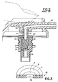
- the invention concerns substituting for the valve stem gasket of the prior art an improved gasket 50, an embodiment of which is shown in Fig. 3 .
- the gasket generally designated as 50, has a central aperture 52 and three zones of varying durometer, namely, zones A, B and C.
- the inner zone A (zone nearest to aperture 52) has the lowest durometer.
- Contiguous to inner zone A is zone B, which has a higher durometer.
- Zone C the outer portion of the gasket 50 has the highest durometer.
- a typical, conventional aerosol gasket has an:
- the gasket may be formed of any elastomeric materials, examples of which are shown in Table 1 below.
- the zones of varying durometer may all be composed of the same material or may each be composed of a different type of elastomeric material or any combination of the foregoing.
- a type of nitrile rubber commonly referred to as Buna N is widely used for aerosol gaskets.
- An improved gasket can be made by forming the gasket out of Buna N rubber with durometers of 50-60, 63-73 and 75-85, Shore A, in zones A, B and C, respectively.
- the preferred construction of an improved gasket utilizes a TPR from the TPV category.
- a TPV material having a finely divided EPDM rubber for the elastomer phase, dispersed in a continuous polypropylene matrix is used.
- the durometer of this material should be 50-60, 63-73 and 75-85, Shore A, in zones A, B & C respectively.
- Elastomers Conventional/Thermoset rubber categories: Common Name Chemical Name Natural Rubber polyisoprene Butyl Rubber polyisobutylene-isoprene Nitrile Rubber acrylonitrile-butadiene Copolymer EPDM Rubber terpolymer of ethylene, propylene and a diene monomer Neoprene Rubber polychloroprene TPR/Thermoplastic rubber categories: Common Name Thermoplastic copolyesters (COP) Thermoplastic elastomeric olefins (TEO) Thermoplastic vulcanizates (TPV) Thermoplastic styrene block copolymers
- Thermoset rubbers must all be cured by the addition of sulfur or hydrogen peroxide or cured by irradiation; these procedures being well known to those skilled in the art of preparing gasket material.
- variable durometer gasket of this invention may be manufactured by conventional coextrusion equipment.
- a tubular member having three materials of varying durometer are simultaneously co-extruded.
- the individual gaskets are formed by die cutting the tubular member into the desired thickness.
- the improvement of this invention will result if the durometer is varied between 45 - 85 Shore A. It should be understood that while a three zoned variable durometer gasket is the preferred form, a two zoned and four or more zones are also contemplated by the subject invention. Critical to the invention is that the zone nearest the central aperture of the gasket be of a lower durometer than the radially outward zone whereat crimping of the upper wall of the valve housing and the underside of the gasket takes place.
- the low durometer portion of the gasket may extend from the central opening of the gasket to the portion of the gasket whereat the valve housing wall crimps into and contacts the underside of the gasket, whereat the durometer hardness is increased for some or all of the zone of contact between the valve housing wall and the underside of the gasket.
- valve housing As noted earlier, in the instance where the outer valve housing wall is castellated, it is a preferred embodiment to use a gasket having a lower durometer such as at the inner zone of the gasket, or a still lower durometer.
- a gasket having a lower durometer such as at the inner zone of the gasket, or a still lower durometer.
- Such a valve housing is shown and described in United States Patent Nos. 4,015,752 ('752) at Figure 2 and the related text material of the '752 patent and 4,015,757 ('757) at Figure 3 and the related text material of the '757 patent, which portions of the noted United States patents are incorporated by reference.
- lower durometer gaskets provide better sealing at the orifices in the annular valve stem groove but that said lower durometer gasket has poorer mechanical properties, e.g., tensile strength, compression set, creep/cold flow, and greater swelling.
- Higher durometer gaskets of the same material in general, have poorer sealing qualities (relative to low durometer gaskets), but have better mechanical properties and less swelling.
- Higher durometer gaskets form a more stable assembly in the area of the crimp of the valve to the mounting cup.
- Low durometer gaskets may develop leak paths in the crimp area due to compression set and creep/cold flow.
Landscapes
- Engineering & Computer Science (AREA)
- General Engineering & Computer Science (AREA)
- Mechanical Engineering (AREA)
- Chemical & Material Sciences (AREA)
- Dispersion Chemistry (AREA)
- Containers And Packaging Bodies Having A Special Means To Remove Contents (AREA)
- Nozzles (AREA)
- Gasket Seals (AREA)
- Lift Valve (AREA)
Claims (9)
- Soupape de bombe aérosol (10) comprenant une tige de soupape creuse (16), un corps de tige de soupape (20), un logement de soupape (26) entourant le corps de tige de soupape (20), une partie intermédiaire (22) entre la tige de soupape (16) et le corps de tige de soupape (20) comprenant au moins un orifice (24) en communication avec l'intérieur de la tige de soupape creuse (16) et l'intérieur du logement de soupape (26) et un joint de tige de soupape (40, 50) comprenant une ouverture centrale (52) encerclant et fermant hermétiquement tous les orifices (24) dans la partie intermédiaire (22), ladite partie intermédiaire (22) étant capable de se déplacer pour exposer au moins un orifice (24) dans la partie intermédiaire (22) par contact avec le joint de tige de soupape (40, 50) et ouvrir ainsi le soupape,
caractérisée en ce que :le joint de tige de soupape (40, 50) comprend plusieurs zones de duromètre variable, la zone (A) la plus proche de l'ouverture centrale (52) et se fermant contre l'orifice (24) dans la partie intermédiaire (22) ayant un duromètre inférieur par rapport au duromètre de la zone (B, C) plus éloignée radialement vers l'extérieur de l'ouverture (52). - Soupape de bombe aérosol (10) selon la revendication 1, dans laquelle les plusieurs zones du joint de tige de soupape (40, 50) comprennent une première zone (A) la plus proche de l'ouverture centrale (52) ayant un duromètre relativement réduit, une zone intermédiaire (B) radialement vers l'extérieur de la première zone (A) ayant un duromètre relativement supérieur au duromètre de la première zone (A) et une zone extérieure (C) radialement vers l'extérieur de la zone intermédiaire (B) ayant un duromètre relativement supérieur à celui de la zone intermédiaire (B).
- Soupape de bombe aérosol (10) selon la revendication 2, dans laquelle la première zone (A) du joint à plusieurs zones (40, 50) a un duromètre compris entre 45 et 65 Shore A, la zone intermédiaire (B) a un duromètre compris entre 60 et 75 Shore A, et la zone extérieure (C) a un duromètre compris entre 70 et 85 Shore A, pourvu également que chaque zone successive s'étendant radialement vers l'extérieur ait un duromètre supérieur.
- Soupape de bombe aérosol (10) selon la revendication 1, dans laquelle le joint à plusieurs zones (40, 50) a un duromètre variable de quatre zones ou plus avec une première zone la plus proche de l'ouverture centrale (52) ayant un duromètre relativement faible et chaque zone successive s'étendant radialement vers l'extérieur ayant un duromètre relativement supérieur.
- Soupape de bombe aérosol (10) selon la revendication 4, dans laquelle le duromètre variable des zones est compris entre 45 et 85 Shore A.
- Soupape de bombe aérosol (10) selon la revendication 1, dans laquelle la zone la plus proche de l'ouverture centrale (52) du joint à plusieurs zones (40, 50) a un duromètre compris entre 45 et 65 Shore A, et une zone plus éloignée radialement vers l'extérieur de la zone la plus proche de l'ouverture centrale (52) a un duromètre compris entre 70 et 85 Shore A.
- Soupape de bombe aérosol (10) selon l'une quelconque des revendications 1 à 6, dans laquelle le logement du soupape (26) comprend une paroi supérieure (36) et un épaulement, le joint de tige de soupape (40, 50) comprend une partie sommitale et une partie inférieure et la bombe aérosol (10) comprend une coupe de montage (34) comprenant une partie de piédestal (32) dans laquelle le logement de soupape (26) est serti de façon à créer un joint entre le côté inférieur du joint et l'épaulement du logement du soupape (26).
- Soupape de bombe aérosol (10) selon la revendication 7, dans laquelle le logement de soupape (26) comprend une paroi extérieure crénelée annulaire et un élément vertical annulaire disposés radialement vers l'intérieur de la paroi extérieure sertie sur le côté inférieur du joint de la tige de soupape (40, 50), et la partie du joint s'étendant sur le périmètre du sertissage entre l'épaulement du logement et le côté inférieur du joint a une valeur de duromètre inférieure à la valeur de duromètre au niveau du sertissage.
- Soupape de bombe aérosol (10) selon la revendication 8, dans laquelle la valeur de duromètre du joint s'étendant sur le périmètre du sertissage a une valeur de duromètre identique ou inférieure à la valeur de duromètre au niveau de la partie du joint la plus proche de l'ouverture centrale du joint.
Applications Claiming Priority (3)
| Application Number | Priority Date | Filing Date | Title |
|---|---|---|---|
| US09/300,541 US6254104B1 (en) | 1999-04-27 | 1999-04-27 | Gasket for an aerosol valve stem |
| US300541 | 1999-04-27 | ||
| PCT/US2000/011312 WO2000065256A1 (fr) | 1999-04-27 | 2000-04-27 | Joint statique ameliore pour tige de clapet de bombe aerosol |
Publications (3)
| Publication Number | Publication Date |
|---|---|
| EP1188007A1 EP1188007A1 (fr) | 2002-03-20 |
| EP1188007A4 EP1188007A4 (fr) | 2006-11-08 |
| EP1188007B1 true EP1188007B1 (fr) | 2008-06-11 |
Family
ID=23159537
Family Applications (1)
| Application Number | Title | Priority Date | Filing Date |
|---|---|---|---|
| EP00926418A Expired - Lifetime EP1188007B1 (fr) | 1999-04-27 | 2000-04-27 | Tige de clapet de bombe aerosol avec un joint statique ameliore |
Country Status (16)
| Country | Link |
|---|---|
| US (1) | US6254104B1 (fr) |
| EP (1) | EP1188007B1 (fr) |
| JP (1) | JP2002543000A (fr) |
| KR (1) | KR100628398B1 (fr) |
| CN (1) | CN1186547C (fr) |
| AR (1) | AR023779A1 (fr) |
| AU (1) | AU758461B2 (fr) |
| BR (1) | BR0010109A (fr) |
| CA (1) | CA2371314A1 (fr) |
| DE (1) | DE60039169D1 (fr) |
| ES (1) | ES2306661T3 (fr) |
| MX (1) | MXPA01010833A (fr) |
| RU (1) | RU2215218C2 (fr) |
| UA (1) | UA72511C2 (fr) |
| WO (1) | WO2000065256A1 (fr) |
| ZA (1) | ZA200108754B (fr) |
Families Citing this family (9)
| Publication number | Priority date | Publication date | Assignee | Title |
|---|---|---|---|---|
| US6832704B2 (en) | 2002-06-17 | 2004-12-21 | Summit Packaging Systems, Inc. | Metering valve for aerosol container |
| WO2005014078A2 (fr) * | 2003-07-28 | 2005-02-17 | 3M Innovative Properties Company | Fermeture par membrane utilisee dans un aerosol medicamenteux |
| US7510167B2 (en) * | 2004-05-03 | 2009-03-31 | Daniel Environmental, Co. Llc | Isolation damper and method of forming airtight seal |
| JP4654747B2 (ja) | 2005-04-14 | 2011-03-23 | トヨタ自動車株式会社 | 流体用開閉弁装置 |
| US20090239180A1 (en) * | 2007-06-26 | 2009-09-24 | Lim Walter K | Aerosol candle snuffer using non-flammable gas |
| WO2009004097A1 (fr) * | 2007-07-05 | 2009-01-08 | Aster De Schrijver | Soupape pour aérosol |
| US8523503B2 (en) * | 2010-07-30 | 2013-09-03 | Nuovo Pignone, S.P.A. | Threaded joint and method of sealing a threaded joint |
| EP2665561B1 (fr) * | 2011-01-21 | 2022-01-19 | The Gillette Company LLC | Actionneur pour un appareil distributeur |
| CN110388461A (zh) * | 2018-04-16 | 2019-10-29 | 中国石油大学(北京) | 一种橡胶密封圈及其制备方法与应用 |
Family Cites Families (15)
| Publication number | Priority date | Publication date | Assignee | Title |
|---|---|---|---|---|
| US2750322A (en) * | 1951-03-20 | 1956-06-12 | Crown Cork & Seal Co | Gasket and method of making same |
| FR1283703A (fr) * | 1961-03-15 | 1962-02-02 | Precision Valve Corp | Bouton pour l'actionnement de la valve commandant la sortie d'un aérosol hors de son récipient |
| AU434054B2 (en) * | 1967-12-18 | 1973-03-22 | Aerosol valve assembly | |
| DE2162762B1 (de) * | 1971-12-17 | 1973-01-25 | Deutsche Praezisions-Ventil Gmbh, 6234 Hattersheim | Ventil für Druckgaspackungen |
| BE790846A (fr) * | 1972-01-12 | 1973-02-15 | Federal Mogul Supertex | Dispositif annulaire d'etancheite |
| US3795350A (en) * | 1972-10-16 | 1974-03-05 | Scovill Manufacturing Co | Aerosol valve having selectable flow rate |
| AU472208B2 (en) * | 1973-03-07 | 1976-05-20 | Precision Valve Australia Pty. Ltd | Pressurized dispenser valve |
| DE2556165A1 (de) * | 1975-01-29 | 1977-06-23 | Praezisions Ventil Gmbh | Ventil fuer druckgaspackungen |
| ES444669A1 (es) * | 1975-01-29 | 1977-05-16 | Precision Valve Corp | Perfeccionamientos en valvulas distribuidoras de productos gaseosos a presion. |
| US4135648A (en) * | 1977-10-26 | 1979-01-23 | Summit Packaging Systems, Inc. | Metering valve for pressurized dispensing containers |
| US4240467A (en) * | 1979-01-15 | 1980-12-23 | Blatt L Douglas | Valve assembly |
| US4243235A (en) * | 1979-07-02 | 1981-01-06 | The Mather Company | Composite polytetrafluoroethylene and elastomer lip seal |
| GB8319353D0 (en) * | 1983-07-18 | 1983-08-17 | Aerosol Inventions Dev | Valve assembly |
| US5609343A (en) * | 1994-10-14 | 1997-03-11 | Smc Corporation | Sealing rings for spool valves |
| US5842701A (en) * | 1996-10-08 | 1998-12-01 | Smith International, Inc. | Dual functioning seal for rock bits |
-
1999
- 1999-04-27 US US09/300,541 patent/US6254104B1/en not_active Expired - Fee Related
-
2000
- 2000-04-27 CN CNB008077576A patent/CN1186547C/zh not_active Expired - Fee Related
- 2000-04-27 AR ARP000102003A patent/AR023779A1/es active IP Right Grant
- 2000-04-27 MX MXPA01010833A patent/MXPA01010833A/es active IP Right Grant
- 2000-04-27 CA CA002371314A patent/CA2371314A1/fr not_active Abandoned
- 2000-04-27 WO PCT/US2000/011312 patent/WO2000065256A1/fr not_active Ceased
- 2000-04-27 UA UA2001107228A patent/UA72511C2/uk unknown
- 2000-04-27 AU AU44949/00A patent/AU758461B2/en not_active Ceased
- 2000-04-27 RU RU2001131897/06A patent/RU2215218C2/ru not_active IP Right Cessation
- 2000-04-27 JP JP2000613962A patent/JP2002543000A/ja active Pending
- 2000-04-27 EP EP00926418A patent/EP1188007B1/fr not_active Expired - Lifetime
- 2000-04-27 DE DE60039169T patent/DE60039169D1/de not_active Expired - Fee Related
- 2000-04-27 ES ES00926418T patent/ES2306661T3/es not_active Expired - Lifetime
- 2000-04-27 BR BR0010109-5A patent/BR0010109A/pt not_active IP Right Cessation
- 2000-04-27 KR KR1020017013778A patent/KR100628398B1/ko not_active Expired - Fee Related
-
2001
- 2001-10-24 ZA ZA200108754A patent/ZA200108754B/en unknown
Also Published As
| Publication number | Publication date |
|---|---|
| BR0010109A (pt) | 2002-04-23 |
| AR023779A1 (es) | 2002-09-04 |
| EP1188007A4 (fr) | 2006-11-08 |
| AU758461B2 (en) | 2003-03-20 |
| KR100628398B1 (ko) | 2006-09-26 |
| CN1351697A (zh) | 2002-05-29 |
| RU2215218C2 (ru) | 2003-10-27 |
| UA72511C2 (en) | 2005-03-15 |
| CA2371314A1 (fr) | 2000-11-02 |
| EP1188007A1 (fr) | 2002-03-20 |
| AU4494900A (en) | 2000-11-10 |
| US6254104B1 (en) | 2001-07-03 |
| DE60039169D1 (de) | 2008-07-24 |
| MXPA01010833A (es) | 2002-11-04 |
| JP2002543000A (ja) | 2002-12-17 |
| KR20020005726A (ko) | 2002-01-17 |
| ES2306661T3 (es) | 2008-11-16 |
| ZA200108754B (en) | 2002-06-13 |
| WO2000065256A1 (fr) | 2000-11-02 |
| CN1186547C (zh) | 2005-01-26 |
Similar Documents
| Publication | Publication Date | Title |
|---|---|---|
| US4015752A (en) | Rapid charging valve for a pressurized dispenser | |
| KR100676343B1 (ko) | 에어로졸 분말 밸브 | |
| US7523767B2 (en) | Means and method for filling bag-on-valve aerosol barrier packs | |
| US5785301A (en) | Tilt opening valve assembly | |
| US6394321B1 (en) | Aerosol powder valve | |
| US4078705A (en) | Valves for pressurized dispensers | |
| EP1188007B1 (fr) | Tige de clapet de bombe aerosol avec un joint statique ameliore | |
| US8070017B2 (en) | Unified mounting cup and valve stem assembly | |
| US6371338B1 (en) | Valve arrangement for discharging a fluid medium maintained under pressure in a container | |
| EP0538403A1 (fr) | Joint multicouche pour fermeture de recipient de type aerosol | |
| CA2415945C (fr) | Valve d'aerosol a ouverture rapide | |
| EP1753675A1 (fr) | Soupapes presentant un joint annulaire plat de hauteur reduite | |
| US4503999A (en) | Dispensing valve assembly for a pressurized container | |
| US3618832A (en) | Fast fill valve assembly for pressurized dispensing package | |
| JPS6135908B2 (fr) | ||
| US4405065A (en) | Tilt valve structure with bridged stop for viscous flow liquids | |
| MXPA00012209A (en) | Aerosol powder valve |
Legal Events
| Date | Code | Title | Description |
|---|---|---|---|
| PUAI | Public reference made under article 153(3) epc to a published international application that has entered the european phase |
Free format text: ORIGINAL CODE: 0009012 |
|
| 17P | Request for examination filed |
Effective date: 20011025 |
|
| AK | Designated contracting states |
Kind code of ref document: A1 Designated state(s): AT BE CH CY DE DK ES FI FR GB GR IE IT LI LU MC NL PT SE |
|
| REG | Reference to a national code |
Ref country code: ES Ref legal event code: GD2A Effective date: 20040203 |
|
| RBV | Designated contracting states (corrected) |
Designated state(s): DE ES FR GB IT NL |
|
| A4 | Supplementary search report drawn up and despatched |
Effective date: 20061010 |
|
| 17Q | First examination report despatched |
Effective date: 20070222 |
|
| RIC1 | Information provided on ipc code assigned before grant |
Ipc: F16J 15/14 20060101ALN20070827BHEP Ipc: B65D 83/44 20060101AFI20070827BHEP |
|
| RTI1 | Title (correction) |
Free format text: AEROSOL VALVE STEM WITH AN IMPROVED GASKET |
|
| GRAP | Despatch of communication of intention to grant a patent |
Free format text: ORIGINAL CODE: EPIDOSNIGR1 |
|
| GRAS | Grant fee paid |
Free format text: ORIGINAL CODE: EPIDOSNIGR3 |
|
| GRAA | (expected) grant |
Free format text: ORIGINAL CODE: 0009210 |
|
| AK | Designated contracting states |
Kind code of ref document: B1 Designated state(s): DE ES FR GB IT NL |
|
| REG | Reference to a national code |
Ref country code: GB Ref legal event code: FG4D |
|
| REF | Corresponds to: |
Ref document number: 60039169 Country of ref document: DE Date of ref document: 20080724 Kind code of ref document: P |
|
| REG | Reference to a national code |
Ref country code: ES Ref legal event code: FG2A Ref document number: 2306661 Country of ref document: ES Kind code of ref document: T3 |
|
| PLBE | No opposition filed within time limit |
Free format text: ORIGINAL CODE: 0009261 |
|
| STAA | Information on the status of an ep patent application or granted ep patent |
Free format text: STATUS: NO OPPOSITION FILED WITHIN TIME LIMIT |
|
| 26N | No opposition filed |
Effective date: 20090312 |
|
| GBPC | Gb: european patent ceased through non-payment of renewal fee |
Effective date: 20090427 |
|
| NLV4 | Nl: lapsed or anulled due to non-payment of the annual fee |
Effective date: 20091101 |
|
| REG | Reference to a national code |
Ref country code: FR Ref legal event code: ST Effective date: 20091231 |
|
| PG25 | Lapsed in a contracting state [announced via postgrant information from national office to epo] |
Ref country code: DE Free format text: LAPSE BECAUSE OF NON-PAYMENT OF DUE FEES Effective date: 20091103 |
|
| PG25 | Lapsed in a contracting state [announced via postgrant information from national office to epo] |
Ref country code: NL Free format text: LAPSE BECAUSE OF NON-PAYMENT OF DUE FEES Effective date: 20091101 |
|
| PG25 | Lapsed in a contracting state [announced via postgrant information from national office to epo] |
Ref country code: GB Free format text: LAPSE BECAUSE OF NON-PAYMENT OF DUE FEES Effective date: 20090427 Ref country code: FR Free format text: LAPSE BECAUSE OF NON-PAYMENT OF DUE FEES Effective date: 20091222 |
|
| REG | Reference to a national code |
Ref country code: ES Ref legal event code: FD2A Effective date: 20090428 |
|
| PG25 | Lapsed in a contracting state [announced via postgrant information from national office to epo] |
Ref country code: ES Free format text: LAPSE BECAUSE OF NON-PAYMENT OF DUE FEES Effective date: 20090428 |
|
| PG25 | Lapsed in a contracting state [announced via postgrant information from national office to epo] |
Ref country code: IT Free format text: LAPSE BECAUSE OF NON-PAYMENT OF DUE FEES Effective date: 20090427 |