EP1188470A2 - Procédé d'adsorption à pression alternée comprenant une couche d'adsorbant mixte - Google Patents
Procédé d'adsorption à pression alternée comprenant une couche d'adsorbant mixte Download PDFInfo
- Publication number
- EP1188470A2 EP1188470A2 EP01122113A EP01122113A EP1188470A2 EP 1188470 A2 EP1188470 A2 EP 1188470A2 EP 01122113 A EP01122113 A EP 01122113A EP 01122113 A EP01122113 A EP 01122113A EP 1188470 A2 EP1188470 A2 EP 1188470A2
- Authority
- EP
- European Patent Office
- Prior art keywords
- adsorbent
- region
- bed
- adsorbents
- recited
- Prior art date
- Legal status (The legal status is an assumption and is not a legal conclusion. Google has not performed a legal analysis and makes no representation as to the accuracy of the status listed.)
- Withdrawn
Links
- 239000003463 adsorbent Substances 0.000 title claims abstract description 230
- 238000001179 sorption measurement Methods 0.000 title description 47
- 230000007704 transition Effects 0.000 claims abstract description 60
- 239000000463 material Substances 0.000 claims abstract description 51
- 239000000203 mixture Substances 0.000 claims abstract description 51
- 239000002245 particle Substances 0.000 claims description 45
- 238000000926 separation method Methods 0.000 abstract description 39
- 238000000034 method Methods 0.000 description 52
- 230000008569 process Effects 0.000 description 46
- 238000012546 transfer Methods 0.000 description 37
- 230000008901 benefit Effects 0.000 description 10
- 239000007789 gas Substances 0.000 description 10
- 238000002156 mixing Methods 0.000 description 10
- 230000006872 improvement Effects 0.000 description 9
- 230000000694 effects Effects 0.000 description 8
- 230000004907 flux Effects 0.000 description 8
- 239000011324 bead Substances 0.000 description 7
- IJGRMHOSHXDMSA-UHFFFAOYSA-N Atomic nitrogen Chemical compound N#N IJGRMHOSHXDMSA-UHFFFAOYSA-N 0.000 description 6
- 238000012856 packing Methods 0.000 description 6
- 238000005382 thermal cycling Methods 0.000 description 6
- 238000003795 desorption Methods 0.000 description 5
- 239000012530 fluid Substances 0.000 description 4
- 238000009434 installation Methods 0.000 description 4
- 238000005192 partition Methods 0.000 description 4
- 238000011084 recovery Methods 0.000 description 4
- 229910021536 Zeolite Inorganic materials 0.000 description 3
- 230000002411 adverse Effects 0.000 description 3
- 239000006185 dispersion Substances 0.000 description 3
- 238000001033 granulometry Methods 0.000 description 3
- 229910052757 nitrogen Inorganic materials 0.000 description 3
- 230000009467 reduction Effects 0.000 description 3
- 239000010457 zeolite Substances 0.000 description 3
- VYPSYNLAJGMNEJ-UHFFFAOYSA-N Silicium dioxide Chemical compound O=[Si]=O VYPSYNLAJGMNEJ-UHFFFAOYSA-N 0.000 description 2
- PNEYBMLMFCGWSK-UHFFFAOYSA-N aluminium oxide Inorganic materials [O-2].[O-2].[O-2].[Al+3].[Al+3] PNEYBMLMFCGWSK-UHFFFAOYSA-N 0.000 description 2
- 150000001768 cations Chemical class 0.000 description 2
- 230000003247 decreasing effect Effects 0.000 description 2
- 230000001419 dependent effect Effects 0.000 description 2
- 238000013461 design Methods 0.000 description 2
- 238000012986 modification Methods 0.000 description 2
- 230000004048 modification Effects 0.000 description 2
- 230000000704 physical effect Effects 0.000 description 2
- 238000011027 product recovery Methods 0.000 description 2
- 238000010926 purge Methods 0.000 description 2
- 239000002250 absorbent Substances 0.000 description 1
- 230000002745 absorbent Effects 0.000 description 1
- 239000006096 absorbing agent Substances 0.000 description 1
- 239000002156 adsorbate Substances 0.000 description 1
- JYIBXUUINYLWLR-UHFFFAOYSA-N aluminum;calcium;potassium;silicon;sodium;trihydrate Chemical group O.O.O.[Na].[Al].[Si].[K].[Ca] JYIBXUUINYLWLR-UHFFFAOYSA-N 0.000 description 1
- QVGXLLKOCUKJST-UHFFFAOYSA-N atomic oxygen Chemical compound [O] QVGXLLKOCUKJST-UHFFFAOYSA-N 0.000 description 1
- UNYSKUBLZGJSLV-UHFFFAOYSA-L calcium;1,3,5,2,4,6$l^{2}-trioxadisilaluminane 2,4-dioxide;dihydroxide;hexahydrate Chemical compound O.O.O.O.O.O.[OH-].[OH-].[Ca+2].O=[Si]1O[Al]O[Si](=O)O1.O=[Si]1O[Al]O[Si](=O)O1 UNYSKUBLZGJSLV-UHFFFAOYSA-L 0.000 description 1
- 229910052676 chabazite Inorganic materials 0.000 description 1
- 230000008859 change Effects 0.000 description 1
- 229910001603 clinoptilolite Inorganic materials 0.000 description 1
- 230000007423 decrease Effects 0.000 description 1
- 238000010586 diagram Methods 0.000 description 1
- 238000009792 diffusion process Methods 0.000 description 1
- HNPSIPDUKPIQMN-UHFFFAOYSA-N dioxosilane;oxo(oxoalumanyloxy)alumane Chemical compound O=[Si]=O.O=[Al]O[Al]=O HNPSIPDUKPIQMN-UHFFFAOYSA-N 0.000 description 1
- 238000001035 drying Methods 0.000 description 1
- 239000003546 flue gas Substances 0.000 description 1
- 230000005484 gravity Effects 0.000 description 1
- 230000010354 integration Effects 0.000 description 1
- 150000002500 ions Chemical group 0.000 description 1
- 229910052680 mordenite Inorganic materials 0.000 description 1
- 230000010355 oscillation Effects 0.000 description 1
- 239000001301 oxygen Substances 0.000 description 1
- 229910052760 oxygen Inorganic materials 0.000 description 1
- 239000011148 porous material Substances 0.000 description 1
- 230000004044 response Effects 0.000 description 1
- 229920006395 saturated elastomer Polymers 0.000 description 1
- 239000000377 silicon dioxide Substances 0.000 description 1
- 238000004513 sizing Methods 0.000 description 1
- 229910052719 titanium Inorganic materials 0.000 description 1
- 239000010936 titanium Substances 0.000 description 1
- -1 titanium silicates Chemical class 0.000 description 1
- 239000011800 void material Substances 0.000 description 1
- XLYOFNOQVPJJNP-UHFFFAOYSA-N water Substances O XLYOFNOQVPJJNP-UHFFFAOYSA-N 0.000 description 1
Images



Classifications
-
- B—PERFORMING OPERATIONS; TRANSPORTING
- B01—PHYSICAL OR CHEMICAL PROCESSES OR APPARATUS IN GENERAL
- B01D—SEPARATION
- B01D53/00—Separation of gases or vapours; Recovering vapours of volatile solvents from gases; Chemical or biological purification of waste gases, e.g. engine exhaust gases, smoke, fumes, flue gases, aerosols
- B01D53/02—Separation of gases or vapours; Recovering vapours of volatile solvents from gases; Chemical or biological purification of waste gases, e.g. engine exhaust gases, smoke, fumes, flue gases, aerosols by adsorption, e.g. preparative gas chromatography
- B01D53/04—Separation of gases or vapours; Recovering vapours of volatile solvents from gases; Chemical or biological purification of waste gases, e.g. engine exhaust gases, smoke, fumes, flue gases, aerosols by adsorption, e.g. preparative gas chromatography with stationary adsorbents
- B01D53/047—Pressure swing adsorption
-
- B—PERFORMING OPERATIONS; TRANSPORTING
- B01—PHYSICAL OR CHEMICAL PROCESSES OR APPARATUS IN GENERAL
- B01D—SEPARATION
- B01D53/00—Separation of gases or vapours; Recovering vapours of volatile solvents from gases; Chemical or biological purification of waste gases, e.g. engine exhaust gases, smoke, fumes, flue gases, aerosols
- B01D53/02—Separation of gases or vapours; Recovering vapours of volatile solvents from gases; Chemical or biological purification of waste gases, e.g. engine exhaust gases, smoke, fumes, flue gases, aerosols by adsorption, e.g. preparative gas chromatography
- B01D53/04—Separation of gases or vapours; Recovering vapours of volatile solvents from gases; Chemical or biological purification of waste gases, e.g. engine exhaust gases, smoke, fumes, flue gases, aerosols by adsorption, e.g. preparative gas chromatography with stationary adsorbents
- B01D53/047—Pressure swing adsorption
- B01D53/0476—Vacuum pressure swing adsorption
-
- B—PERFORMING OPERATIONS; TRANSPORTING
- B01—PHYSICAL OR CHEMICAL PROCESSES OR APPARATUS IN GENERAL
- B01D—SEPARATION
- B01D2256/00—Main component in the product gas stream after treatment
- B01D2256/16—Hydrogen
-
- B—PERFORMING OPERATIONS; TRANSPORTING
- B01—PHYSICAL OR CHEMICAL PROCESSES OR APPARATUS IN GENERAL
- B01D—SEPARATION
- B01D2257/00—Components to be removed
- B01D2257/10—Single element gases other than halogens
- B01D2257/102—Nitrogen
-
- B—PERFORMING OPERATIONS; TRANSPORTING
- B01—PHYSICAL OR CHEMICAL PROCESSES OR APPARATUS IN GENERAL
- B01D—SEPARATION
- B01D2257/00—Components to be removed
- B01D2257/10—Single element gases other than halogens
- B01D2257/104—Oxygen
-
- B—PERFORMING OPERATIONS; TRANSPORTING
- B01—PHYSICAL OR CHEMICAL PROCESSES OR APPARATUS IN GENERAL
- B01D—SEPARATION
- B01D2259/00—Type of treatment
- B01D2259/40—Further details for adsorption processes and devices
- B01D2259/414—Further details for adsorption processes and devices using different types of adsorbents
- B01D2259/4141—Further details for adsorption processes and devices using different types of adsorbents within a single bed
- B01D2259/4143—Further details for adsorption processes and devices using different types of adsorbents within a single bed arranged as a mixture
-
- B—PERFORMING OPERATIONS; TRANSPORTING
- B01—PHYSICAL OR CHEMICAL PROCESSES OR APPARATUS IN GENERAL
- B01D—SEPARATION
- B01D2259/00—Type of treatment
- B01D2259/40—Further details for adsorption processes and devices
- B01D2259/414—Further details for adsorption processes and devices using different types of adsorbents
- B01D2259/4141—Further details for adsorption processes and devices using different types of adsorbents within a single bed
- B01D2259/4145—Further details for adsorption processes and devices using different types of adsorbents within a single bed arranged in series
- B01D2259/4146—Contiguous multilayered adsorbents
Definitions
- This invention relates to pressure swing adsorption (PSA) and vacuum pressure swing adsorption (VPSA) gas separation systems and, more particularly, to a method and apparatus for employing a mixed transition adsorbent layer in PSA and VPSA adsorbent bed systems having two or more layers of adsorbent materials.
- PSA pressure swing adsorption
- VPSA vacuum pressure swing adsorption
- Layers of different adsorbents have been introduced in the prior art to address the need for multiple separation zones to remove or separate more than a single component from a gas feed stream. For various reasons, the interface between layers has been distinct to coincide with a sharp boundary between the separation zones. Any layer may consist of either a single adsorbent or a uniform blend of materials. While multilayers with sharp interfaces offer improvements over a single adsorbent in certain applications, they limit the degree to which the adsorption material can be tailored to the process requirements.
- Prior art adsorbent loading apparatus have provided loading and dense packing of materials, but have been limited in design to loading only a single adsorbent or uniform blend of adsorbents within each region or layer of the adsorbent.
- Such loading systems are capable of simultaneously loading different adsorbents into separate regions or layers of a radial bed adsorbent.
- the prior art teaches a plurality of devices for loading of adsorbents into beds and various arrangements of adsorbents in the respective beds. Such prior art is considered below.
- U.S. Patent 5,837,021 entitled “Installation for the Treatment of at Least one fluid, by Passage through two adjacent Masses of Material” describes a dump cart type loader assembly that creates a layered adsorbent within a radial flow adsorbent vessel with a distinctly sharp vertical interface between the layers of materials.
- the patent also indicates that the layered bed configuration exhibits adsorbents in direct contact with each other.
- U.S. Patent 5,931,980 entitled “Installation for the Treatment of at Least One Fluid, by Passage Through Two Adjacent Masses of Material” discloses a layered adsorbent bed within a vessel such as a radial flow adsorbent vessel with a sharp interface between the layers of materials. It is indicated that the bed may exhibit a continuous interface that may be "wavy" in nature.
- U.S. Patent 5,176,721 entitled “Adsorbent and Process of the Separation by Adsorption” employs a sequence for loading a cylindrical bed in the horizontal position followed by rotating to the vertical position for operation. This sequence allows for the gravity-enhanced loading of one adsorbent at a time, ultimately achieving vertical layers of adsorbent with a sharp direct-contact interface. This vertically orientated, vertically layered cylindrical bed is then operated with horizontal flow through the layers.
- U.S. Patent 5,324,159 entitled “Particle Loader” describes the use of a rotating loader arm assembly for the installation of layers of individual adsorbents.
- the loader system is particularly suited to loading adsorbents in axial flow beds.
- U.S. Patent 5,836,362 entitled “Multiple Adsorbent Loader Method and Apparatus for a Radial Flow Vessel” describes a loader assembly that loads multiple adsorbents into a radial flow bed adsorbent vessel while creating a sharp interface between layers.
- the material in any layer may be a single adsorbent or a uniform mixture of adsorbents.
- This patent also describes loading criteria for achieving the desired sharp layer interface.
- U.S. Patent 4,964,888 entitled “Multiple Zone Adsorption Process” describes an adsorbent that includes plural layers of adsorbent, the respective layers having different bead sizes selected for mass transfer rate improvement.
- the patent also describes the presence of a third layer placed between the two layers comprised of a blend of the materials of the adjacent layers. No method is given for the loading such layers.
- UK Patent Application 2,300,577 entitled “Sorbing Apparatus” describes an adsorption apparatus with adsorbents of various bead sizes.
- the Application shows both a layered mesh size bed and a non-layered bed of varying particle size in a manner similar to that of 4,964,888.
- the invention incorporates a mixed adsorbent transition region comprised of a graduated composition of the adjacent layered materials between distinct layers of adsorbents contained within an adsorbent bed.
- This region of mixed adsorbents results in an improvement in process efficiency and an overall reduction in product cost compared to multilayered systems with sharp interfaces.
- a loader assembly incorporating the invention is designed to simultaneously load multiple layers comprising different adsorbents while controlling the mixed transition region between these layers. Further, the loader assembly continuously controls the disposition of materials within this mixed transition region.
- the depth and composition of adsorbents within the mixed transition region are established by process requirements and implemented by the adsorbent loader installation.
- the desired material composition gradient within the mixed transition region is graduated from ⁇ 100% material of the adjacent layer to a 50% blend somewhere within the region, to ⁇ 100% of the other material at the far end of the mixed transition region.
- the minimum depth of the mixed transition region is twenty particle diameters.
- Fig. 1A illustrates a typical VPSA cycle step diagram.
- Fig. 1B illustrates typical VPSA process conditions.
- Fig. 2 illustrates bed adsorption zones.
- Fig. 3 illustrates average bed temperature profiles at the end of adsorption and desorption steps.
- Fig. 4A illustrates a mixed transition bed configuration exploiting adsorber bed temperature profiles.
- Fig. 4B illustrates a mixed transition bed configuration exploiting bead size variation.
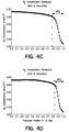
- Fig. 4C illustrates nitrogen concentration distribution at the end of adsorption for LiX at 1.6mm average particle diameter.
- Fig. 4D illustrates nitrogen concentration distribution at the end of adsorption for LiX at 1.13mm average particle diameter.
- Fig. 5A illustrates an axial bed loader arm assembly in accord with an embodiment of the invention.
- Fig. 5B illustrates an sectional view of an axial bed loader arm.
- Fig. 5C illustrates valve plates that are incorporated into axial bed loader arm to control adsorbent flow therefrom.
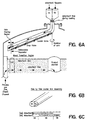
- Fig. 6A illustrates a radial bed loader arm assembly in accord with an embodiment of the invention.
- Fig. 6B illustrates an sectional view of a radial bed loader arm.
- Fig. 6C illustrates apertures that are incorporated into channels of the radial bed loader arm to enable creation of a mixed adsorbent region in the radial bed.
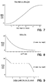
- Fig. 7 illustrates region thickness versus drop height.
- Fig. 8 illustrates region thickness verses loading flux.
- Fig. 9 illustrates region thickness versus partition length.
- this invention comprises an adsorbent bed configuration that includes at least two regions of adsorbents or adsorbent mixtures of uniform composition wherein such regions are separated by a transition zone comprised of a graduated mixture of the materials in the adjacent regions.
- the interfaces of these layered bed regions do not necessarily coincide with the main separation zones within the adsorbent.
- the invention further includes a means by which the adsorbent materials are loaded into the various regions.
- the mixed or transition region of the invention exhibits thermodynamic, kinetic and physical properties related to those of the materials in the adjacent adsorbent layers. Surprisingly, the proper selection and graduation of adsorbents in the mixed region can lead to enhanced process performance. Representative enhancements include increased working capacity, higher selectivity, reduced thermal cycling, lower pressure drop, etc. The type and degree of enhancement depends upon the process, the adsorbents and the depth of the graduated mixture region. Thus, the benefits from applying the inventive mixed transition region can be realized for many different types of separations and adsorbent configurations.
- the invention is applicable to pressure swing adsorption and/or temperature swing adsorption systems having one or more beds and is not dependent upon a particular gas separation or process cycle.
- Process performance is improved due to the selection and mixing of adsorbents to enhance adsorption thermodynamics at the specific temperatures within each region of the adsorbent.
- Zone A is responsible for feed prepurification, specifically the removal of water and CO 2 .
- zone B is the zone where the majority of the desired bulk gas separation occurs.
- zone B is in equilibrium with the feed gas and this is termed the "equilibrium zone".
- a mass transfer front develops at the beginning of the adsorption step in zone B and traverses zone B until it comes to rest in zone C.
- Zone C is termed the "mass transfer" zone.
- Fig. 3 shows a typical temperature gradient along the bed length for a VPSA air separation cycle.
- the bottom or feed end of the adsorbent operates at nearly the same or at a slightly lower temperature as the feed inlet temperature.
- a relatively rapid temperature depression then takes place, reaching a minimum temperature in the lower sections of the adsorbent just at the exit of prepurification zone A.
- the temperature then gradually increases along zones B and C as the product end is approached.
- the maximum temperature is typically reached near the top of the adsorbent at the product end.
- Adsorbents can be selected for this or other processes to operate in regions of the adsorber where adsorbent characteristics are tailored to this temperature profile.
- mixed transition regions can be used to reduce the adverse effects of thermal cycling by integrating the adsorbent mixture properties with the local temperature conditions in the bed. This is accomplished by introducing a material which acts as a heat sink, or by using a weaker adsorbent with a lower heat of adsorption. Mixed regions can be deployed to reduce this unwanted thermal cycling, increase the adsorption efficiency and improve process performance.
- Fig. 4A shows a bed configuration employing a mixed transition region that exploits the temperature conditions present in the bed.
- the process performance is improved by selecting and layering adsorbents on each side of a mixed transition region according to the adsorption properties of the individual adsorbents and their mixtures and tailored to the local temperature conditions in the bed.
- this improved performance is achieved with adsorbent configuration boundaries (aa/ab and ab/bb) that do not necessarily coincide with the separation boundaries (A/B and B/C).
- adsorbent configuration boundaries aa/ab and ab/bb
- the adiabatic separation factor is maximized at each temperature along the bed length.
- a discussion of the adiabatic separation factor is disclosed in commonly assigned US Patent 6,027,548.
- the bed is configured with NaX in region (aa).
- the adsorbent in region aa is operating in the prepurification zone (zone A) of the adsorbent with a rapidly falling temperature profile.
- This region comprises about 5-10% of the total adsorbent.
- Region bb contains LiX and occupies all of zone C and part of zone B of the adsorbent. This region contains about 70-80% of the total adsorbent
- a mixed transition region (ab) is inserted between the layers of the individual LiX and NaX adsorbents.
- the lower end of this region is 100% NaX at the boundary aa/ab, and the composition of this region gradually increases in LiX until 100% LiX is reached at the boundary ab/bb.
- the length of region ab also called the depth of ab
- the required size of the transition region (ab) depends upon the process conditions and the adsorbents. The size of the transition region is thus established upon the basis of the thermal state of the adsorbent in the bed and upon the separation characteristics of the adsorbent mixture.
- the ideal transition region comprises about 10% to about 25% of the overall bed length with that part of the LiX zone where the bed temperature is predominately below about 300-305K in all steps of the cycle being replaced with a graduated mixture of LiX and NaX.
- the transition region thickness not be smaller than about twenty particle diameters: where d p 1 and d p 2 are the average particle sizes of the adsorbents in the graduated mixture. This lower limit is established to insure a sufficient bed length for providing the graduated mixture. In application of the invention, a very steep temperature gradient would result in a shorter mixed region, while a shallow gradient would result in a longer mixed region.
- particle size and particle diameter is defined as the average diameter of all of the particles within an adsorbent region. It is understood by those skilled in the art that commercial adsorbents are typically provided in a range of mesh sizes characterized by an average particle diameter. . It is understood by those skilled in the art that commercial adsorbents are typically supplied as a distribution of particle sizes.
- mixed transition region (ab) allows for the use of additional quantities of NaX, and thereby reduced quantities of the more expensive LiX material. This is possible by capturing the increased separation efficiency of the adsorbent mixture in the lower local temperature regions of the bed.
- the overall adsorbent cost for the process can also be lowered.
- selecting the transition region mixture gradient and region depth to maximize adsorbent efficiency results in an overall process improvement and cost reduction of the product.
- the transition region of the invention may also be used to minimize pressure drop and to optimize rate effects.
- a second means of pressure gradient control is through the control of the adsorbent particle size distribution within a region.
- an adsorption front propagates through the bed in the direction of the feed flow. This mass transfer front is affected by the adsorbent characteristics, gas flow and the specific process steps and times.
- the adsorbent In the lower regions of the adsorbent bed, the adsorbent becomes saturated as the mass transfer front passes by and these regions have sufficient time to reach equilibrium with the feed. Thus the separation efficiency of this lower region is controlled by the equilibrium characteristics of the adsorbent and the conditions of the process.
- the mass transfer zone (MTZ) comes to rest in the upper region of the adsorbent at the end of the adsorption step. The separation efficiency is dominated by the mass transfer rate characteristics of the material in this zone.
- the length of the MTZ affects the overall performance of the process.
- the MTZ is almost entirely contained at the product end of the bed, at the end of the adsorption step, e.g. as illustrated in Figure 4C by the N 2 concentration distribution in a uniform bed of LiX, average particle diameter of 1.6mm.
- Figure 4D shows a similar distribution in a bed for the same type of adsorbent, but with an average particle diameter of 1.13mm.
- the adsorbent region bb of Fig. 4A is subdivided into three smaller regions, with the mixed transition region again sandwiched between two layers of adsorbent of uniform composition.
- This configuration is illustrated in Fig. 4B.
- Layers bb1 and bb3 represent the same adsorbent material but with each layer having a different average particle diameter.
- the lower section of region bb2 is 100% of the larger diameter material, and the size of the adsorbent in this region is graduated to a composition corresponding to 100% of the smaller diameter material at the opposite end of this region.
- This mixing of particles of different granulometry provides a means to manage the competing effects of pressure drop and adsorption rate as average particle size decreases. Thus, adsorbent efficiency may be maximized.
- the size of the mixed transition region (bb2) is determined in response to specific mass transfer zone effects controlled by cycle specific adsorbent and process characteristics.
- the discrete layers on each side of the transition region be composed of the same adsorbent material.
- Uniform high adsorbent packing density is important in the design of high efficiency adsorption processes. This high-density packing improves flow distribution within the adsorbent bed, critical to efficient operation. In addition high adsorbent bed density lowers the interparticle void fraction, yielding improved adsorption efficiency.
- the examples above demonstrate some of the advantages of a mixed transition region.
- This invention is not intended to be limited to only those cases where the advantages of the examples are realized.
- the mixed transition concept is broadly useful in creating a region of unique properties obtained as a combination of the materials in the adjacent layers which may be applied as a means of tailoring any desired property of the adsorption system to achieve the benefits of the mixed transition region mentioned above.
- the adsorbent materials in the layers to be separated by the mixed transition region may differ in composition, such as in physical properties (i.e. particle size, rate and/or equilibrium characteristics) or adsorbent type (e.g. NaX, LiX, NaA, etc.).
- the materials may differ based on the separations to be accomplished in each layer (e.g.
- the adjacent layers may themselves comprise mixtures of adsorbents as disclosed in commonly assigned US Patent 6,027,548.
- an object of the present invention is to make significant improvements in adsorbent utilization and product recovery through enhancement of the rate characteristics of the adsorbent - primarily by increasing the effective diffusivity in the macropores of the adsorbent particle.
- the improved recovery achieved under the conditions of the invention also leads to reduced power consumption per unit of product produced.
- the invention is preferably directed at equilibrium-based adsorption separation processes with mass transport dominated by intraparticle pore diffusion. While the examples have been directed at air separation using a single main adsorbent, the invention is not limited to binary mixtures, nor to air as a feed nor to a single main adsorbent.
- each adsorbent would be responsible for a different separation or a different level of the same separation.
- Multiple mass transfer zones may then be present in the process.
- An analysis similar to that described above would be performed for each of the adsorbent/adsorbate combinations where overcoming significant mass transfer resistance limitations would lead to overall improvements in process performance.
- the properties (particularly those related to the rate of adsorption) of the different adsorbent materials in the main adsorbent zone are selected to maximize all of the separations required of the process.
- Examples of such processes include the recovery of H 2 from H 2 /CO/CO 2 /CH 4 mixtures; prepurification, including the removal of H 2 O and CO 2 from air, separation of Ar from air or N 2 or O 2 , drying of process streams and the recovery of CO 2 from flue gases or from H 2 PSA tail gas.
- Type X zeolite adsorbents are suggested for air separation, most preferably highly-exchanged LiX as described by Chao (U.S. Pat. No. 4,859,217).
- Other type X materials with monovalent cations or mixed cations are also applicable to the present invention such as those suggested by Chao (U.S. Pat. No. 5,174,979).
- the invention is also applicable to any type of equilibrium-selective adsorbent material including, but not limited to, A-zeolite, Y-zeolite, chabazite, mordenite, clinoptilolite and various ion exchanged forms of these, as well as silica-alumina, alumina, silica, titanium silicates and mixtures thereof.
- adsorbents in the main adsorbent zone e.g. layers and mixtures of adsorbents of various types or of the same type but with varying adsorption and/or physical characteristics.
- the enhanced rate concepts of this invention could be applied to the layered beds suggested by Ackley in co-pending EP Publication 0 875,279, as well as Notaro et al (USP 5,674,311) and Watson et al (USP 5,529,610).
- the present invention teaches a method to improve process performance by reducing mass transfer limitations without incurring any increase in process pressure drop.
- Bed depth and cycle time are reduced to compensate for increased specific pressure drop (pressure drop per unit depth of adsorbent) when particle size is reduced.
- pressure drop pressure drop per unit depth of adsorbent
- a poorer sorption rate-quality adsorbent (low mass transfer coefficient) could be used in the equilibrium zone and a higher sorption rate-quality version of the same adsorbent (high mass transfer coefficient) in the mass transfer zone.
- the poorer rate-quality material in this latter condition could also be of smaller diameter. This would result in a configuration with regard to particle sizes in the adsorbent bed that is completely opposite to the prior art teachings. Thus when multiple adsorbents with different rate characteristics must be used, maintaining the adsorbent with the largest mass transfer rate coefficient in the mass transfer zone insures the best overall process performance.
- the rate of adsorption cannot be too low relative to that in a succeeding layer of adsorbent. This is because the leading edge of the mass transfer zone would erupt from the adsorber before the trailing edge crosses the boundary between the two materials. This would result in a reduced size of the equilibrium zone and increased size of the mass transfer zone and consequently, overall lower product recovery and/or purity.
- This condition may be minimized by selecting the adsorbents and the mass transfer coefficients (MTC) of the most selective component such that the size of the mass transfer zone in the adsorbent of the lowest MTC is no more than twice that of the size of the mass transfer zone in the adsorbent of the highest MTC.
- MTC mass transfer coefficients
- the problem may also be solved by distributing the adsorbents in such a way as to achieve a gradual increase in mass transfer coefficients (in contrast to discrete layers) from the inlet to the outlet of the adsorber.
- mass transfer coefficient gradients can be applied individually to each included separation zone.
- VSA subatmospheric
- VPSA transatmospheric
- PSA superatmospheric
- the enhanced-rate concepts described here are not limited to any particular adsorber configuration and can be effectively applied to axial flow, radial flow, lateral flow, etc. adsorbers.
- the adsorbent may be constrained or unconstrained within the absorber vessel.
- the benefits of the invention may also be obtained in cycles in which the primary product is the more selectively adsorbed component (e.g. N 2 ) or in cycles wherein both the more and less strongly held component are recovered as product.
- the primary product is the more selectively adsorbed component (e.g. N 2 ) or in cycles wherein both the more and less strongly held component are recovered as product.
- the invention is applicable to pressure swing adsorption and/or temperature swing adsorption systems having one or more beds and is not dependent upon a particular gas separation or process cycle.
- Apparatus for loading a bed with a mixed transition region Apparatus for loading a bed with a mixed transition region.
- the bed loader described in patent 5,324,159 is modified by this invention to add a separate loader arm channel for each material.
- a sliding valve plate varies the effective hole-size in each loader arm channel.
- Figs. 5A-5C show this loader system.
- the hole-size is variable during loading by adjusting the valve plate shown in Fig. 5C, thereby affecting the flow rate of each specific adsorbent material from its respective channel (see Fig. 5B).
- This control is employed during the loading process to achieve the desired bed composition at each region in the bed, as the loading arm is rotated over the bed.
- the composition at any region can be controlled from 0% - 100% as the bed is loaded from the bottom to the top in the vertical position.
- Figs. 6A-6C show this loader assembly, where control of adsorbent loading is accomplished by the following means:
- the composition is controlled by the following means: 1) adjusting the drop height of the material, 2) varying the adsorbent loading rate flux by adjusting the hole size, rotational speed of the loader arm and/or the bead size 3) adjusting the length of the partition plate suspended from the arm.
- Fig. 7 shows the relationship between the drop height and mixed transition region thickness.
- One major factor affecting the thickness of the mixed region is the bouncing of a fraction of the adsorbent particles as they impact upon the surface of the stationary particles at the top of the bed during loading. This bouncing is a result of the energy contained within the falling particles. Increasing the drop height increases both the energy of the particles and the thickness of the mixed layer.
- Fig. 7 shows that a mixed region as small as ⁇ 2cm can be obtained with a drop height of about 1m. As the drop height is extended to about 8m, the transition region extends to about 25cm.
- Fig. 8 shows the relationship between loading flux (described in units of grams adsorbent/m 2 bed surface area per revolution of the loading arm) and the mixed transition region thickness. As stated earlier, some of the falling adsorbent bounces off the stationary adsorbent and is dispersed in random directions a distance influenced by the energy of the particle and the specific contact surface between the particles.
- Fig. 9 shows the relationship between the partition length and the mixed transition region thickness for a nominal 4m drop height.
- the adsorbent material exiting the holes in the loading arm has some modest radial velocity associated with its trajectory, and thereby generates a wider mixed region.
- the particle deflector is used to reduce this component of velocity and thereby reduce the mixing zone width.
- the deflector plate can also be extended to a position just above the loaded adsorbent bed surface.
- This extended particle baffle can control or eliminate the bouncing effect responsible for dispersion at the top surface of the bed. Control of this length can reduce the transition region to a thickness of ⁇ 2cm for very high drop heights.
- the radial bed loader arm is designed with an overlap in the hole pattern for each material to be loaded.
- Fig. 8C shows a loader arm with the overlapped holes along with the suspended distribution plate. The sizing and spacing of these overlapped holes will determine the mixture composition at the center sections of these relative large mixed transition layers. It will be appreciated that materials being fed to the loader arm may be premixtures of individual adsorbents, thereby providing great flexibility in achieving a wide range of possible adsorbent compositions in the mixed transition region.
Landscapes
- Chemical & Material Sciences (AREA)
- Engineering & Computer Science (AREA)
- Analytical Chemistry (AREA)
- General Chemical & Material Sciences (AREA)
- Oil, Petroleum & Natural Gas (AREA)
- Chemical Kinetics & Catalysis (AREA)
- Separation Of Gases By Adsorption (AREA)
- Medicines Containing Material From Animals Or Micro-Organisms (AREA)
Applications Claiming Priority (2)
| Application Number | Priority Date | Filing Date | Title |
|---|---|---|---|
| US66275400A | 2000-09-15 | 2000-09-15 | |
| US662754 | 2000-09-15 |
Publications (2)
| Publication Number | Publication Date |
|---|---|
| EP1188470A2 true EP1188470A2 (fr) | 2002-03-20 |
| EP1188470A3 EP1188470A3 (fr) | 2003-04-02 |
Family
ID=24659069
Family Applications (1)
| Application Number | Title | Priority Date | Filing Date |
|---|---|---|---|
| EP01122113A Withdrawn EP1188470A3 (fr) | 2000-09-15 | 2001-09-14 | Procédé d'adsorption à pression alternée comprenant une couche d'adsorbant mixte |
Country Status (6)
| Country | Link |
|---|---|
| EP (1) | EP1188470A3 (fr) |
| JP (1) | JP2002153720A (fr) |
| KR (1) | KR20020021616A (fr) |
| CN (1) | CN1344581A (fr) |
| BR (1) | BR0104080A (fr) |
| CA (1) | CA2357276A1 (fr) |
Cited By (8)
| Publication number | Priority date | Publication date | Assignee | Title |
|---|---|---|---|---|
| EP1380336A1 (fr) * | 2002-07-10 | 2004-01-14 | Air Products And Chemicals, Inc. | Opération et optimisation d'un procédé d'adsorption à pression alternée |
| US6866075B2 (en) | 2002-08-09 | 2005-03-15 | Air Products And Chemicals, Inc. | Method and apparatus for uniform particle loading of vessels |
| WO2012136912A1 (fr) | 2011-04-08 | 2012-10-11 | L'air Liquide,Societe Anonyme Pour L'etude Et L'exploitation Des Procedes Georges Claude | Particule d'un matériau à changement de phase avec couche d'enrobage |
| WO2012136913A1 (fr) | 2011-04-08 | 2012-10-11 | L'air Liquide,Societe Anonyme Pour L'etude Et L'exploitation Des Procedes Georges Claude | Mélange d'un adsorbant et d'un matériau à changement de phase à densité adaptée |
| US8329078B2 (en) | 2008-09-25 | 2012-12-11 | L'air Liquide Societe Anonyme Pour L'etude Et L'exploitation Des Procedes Georges Claude | Manufacture of an agglomerate consisting of phase change material and having controlled properties |
| WO2014044968A1 (fr) | 2012-09-21 | 2014-03-27 | L'air Liquide,Societe Anonyme Pour L'etude Et L'exploitation Des Procedes Georges Claude | Mélange adsorbant comprenant des particules d'adsorbant et des particules de matériau à changement de phase |
| WO2016092176A1 (fr) | 2014-12-11 | 2016-06-16 | L'air Liquide, Societe Anonyme Pour L'etude Et L'exploitation Des Procedes Georges Claude | Mélange adsorbant à capacité thermique améliorée |
| WO2026019525A1 (fr) * | 2024-07-16 | 2026-01-22 | Enhanced Energy Group LLC | Récipient de capture pour système de captage de carbone |
Families Citing this family (11)
| Publication number | Priority date | Publication date | Assignee | Title |
|---|---|---|---|---|
| CN102443451B (zh) * | 2011-09-21 | 2014-06-11 | 北京时代桃源环境科技有限公司 | 一种瓦斯气的吸附除湿方法及其装置 |
| CN103055661A (zh) * | 2012-12-31 | 2013-04-24 | 东南大学 | 一种高温脱除烟气中酸性气体的装置及其方法 |
| CN111056586A (zh) * | 2019-11-19 | 2020-04-24 | 南京大学盐城环保技术与工程研究院 | 一种去除废水中有机杂质及硝态氮的多级吸附、脱附装置 |
| US11596895B2 (en) | 2020-07-17 | 2023-03-07 | Air Products And Chemicals, Inc. | Radial adsorber, adsorption system, and adsorption methods |
| US12196486B2 (en) | 2021-07-21 | 2025-01-14 | Air Products And Chemicals, Inc. | Air separation apparatus, adsorber, and method |
| CN113908661A (zh) * | 2021-09-09 | 2022-01-11 | 浙江大学杭州国际科创中心 | 一种立式径向流吸附器 |
| US12247782B2 (en) | 2021-09-23 | 2025-03-11 | Air Products And Chemicals, Inc. | Pre-purification arrangement for air separation and method of hybrid air purification |
| US12595960B2 (en) | 2023-06-26 | 2026-04-07 | Air Products And Chemicals, Inc. | Adsorber, purification system, and purification method |
| CN117018880B (zh) * | 2023-09-15 | 2026-03-27 | 青岛中润设备仪表有限公司 | 一种海水淡化用半透膜及其制备方法 |
| US20250145460A1 (en) | 2023-11-03 | 2025-05-08 | Air Products And Chemicals, Inc. | Adsorbent Material, Adsorption System, and Adsorption Process For Hydrogen Recovery |
| US20250144601A1 (en) | 2023-11-03 | 2025-05-08 | Air Products And Chemicals, Inc. | Adsorbent Material, Adsorption System, and Adsorption Process |
Family Cites Families (4)
| Publication number | Priority date | Publication date | Assignee | Title |
|---|---|---|---|---|
| US3780887A (en) * | 1972-10-10 | 1973-12-25 | Continental Oil Co | Rotary distributor means and method |
| US4964888A (en) * | 1989-12-27 | 1990-10-23 | Uop | Multiple zone adsorption process |
| US5324159A (en) * | 1992-10-02 | 1994-06-28 | Praxair Technology, Inc. | Particle loader |
| US5836362A (en) * | 1997-07-15 | 1998-11-17 | Praxair Technology, Inc. | Multiple adsorbent loading method and apparatus for a radial flow vessel |
-
2001
- 2001-09-14 BR BR0104080-4A patent/BR0104080A/pt not_active Application Discontinuation
- 2001-09-14 CA CA002357276A patent/CA2357276A1/fr not_active Abandoned
- 2001-09-14 KR KR1020010056763A patent/KR20020021616A/ko not_active Ceased
- 2001-09-14 EP EP01122113A patent/EP1188470A3/fr not_active Withdrawn
- 2001-09-14 CN CN01133109A patent/CN1344581A/zh active Pending
- 2001-09-17 JP JP2001281246A patent/JP2002153720A/ja not_active Abandoned
Cited By (9)
| Publication number | Priority date | Publication date | Assignee | Title |
|---|---|---|---|---|
| EP1380336A1 (fr) * | 2002-07-10 | 2004-01-14 | Air Products And Chemicals, Inc. | Opération et optimisation d'un procédé d'adsorption à pression alternée |
| US6866075B2 (en) | 2002-08-09 | 2005-03-15 | Air Products And Chemicals, Inc. | Method and apparatus for uniform particle loading of vessels |
| US8329078B2 (en) | 2008-09-25 | 2012-12-11 | L'air Liquide Societe Anonyme Pour L'etude Et L'exploitation Des Procedes Georges Claude | Manufacture of an agglomerate consisting of phase change material and having controlled properties |
| WO2012136912A1 (fr) | 2011-04-08 | 2012-10-11 | L'air Liquide,Societe Anonyme Pour L'etude Et L'exploitation Des Procedes Georges Claude | Particule d'un matériau à changement de phase avec couche d'enrobage |
| WO2012136913A1 (fr) | 2011-04-08 | 2012-10-11 | L'air Liquide,Societe Anonyme Pour L'etude Et L'exploitation Des Procedes Georges Claude | Mélange d'un adsorbant et d'un matériau à changement de phase à densité adaptée |
| US9314768B2 (en) | 2011-04-08 | 2016-04-19 | L'Air Liquide Société Anonyme pour l'Etude et l'Exploitation des Procédés Georges Claude | Mixture of an adsorbent and a phase change material with an adapted density |
| WO2014044968A1 (fr) | 2012-09-21 | 2014-03-27 | L'air Liquide,Societe Anonyme Pour L'etude Et L'exploitation Des Procedes Georges Claude | Mélange adsorbant comprenant des particules d'adsorbant et des particules de matériau à changement de phase |
| WO2016092176A1 (fr) | 2014-12-11 | 2016-06-16 | L'air Liquide, Societe Anonyme Pour L'etude Et L'exploitation Des Procedes Georges Claude | Mélange adsorbant à capacité thermique améliorée |
| WO2026019525A1 (fr) * | 2024-07-16 | 2026-01-22 | Enhanced Energy Group LLC | Récipient de capture pour système de captage de carbone |
Also Published As
| Publication number | Publication date |
|---|---|
| BR0104080A (pt) | 2002-04-23 |
| CA2357276A1 (fr) | 2002-03-15 |
| JP2002153720A (ja) | 2002-05-28 |
| CN1344581A (zh) | 2002-04-17 |
| EP1188470A3 (fr) | 2003-04-02 |
| KR20020021616A (ko) | 2002-03-21 |
Similar Documents
| Publication | Publication Date | Title |
|---|---|---|
| EP1188470A2 (fr) | Procédé d'adsorption à pression alternée comprenant une couche d'adsorbant mixte | |
| EP1080771B1 (fr) | Procédé pour la séparation de gaz utilisant des particules adsorbantes composites | |
| US8313561B2 (en) | Radial bed vessels having uniform flow distribution | |
| AU2006203931B2 (en) | Engineered adsorbent structures for kinetic separation | |
| EP0172003B1 (fr) | Appareil de sorption | |
| KR100227060B1 (ko) | 기체 정제 방법 및 장치 | |
| DE60030813T2 (de) | Lufttrennung mit einem monolithischen Adsorptionsbett | |
| US6500234B1 (en) | Rate-enhanced gas separation | |
| KR930001608B1 (ko) | 상이한 입도의 흡착제를 함유하는 연속 흡착대역을 이용한 증기상 혼합물의 분리방법 | |
| EP0769320B1 (fr) | Procédé pour la sélection d'adsorbants | |
| JP3167909B2 (ja) | 改良された吸着流れ分布 | |
| CA2432419C (fr) | Procede d'adsorption modulee en pression plus rapide | |
| WO1999043416A1 (fr) | Separation de gaz plus rapide | |
| EP1358924A2 (fr) | Purification des flux de gaz par adsorption | |
| GB2281229A (en) | An adsorber vessel | |
| US6562113B1 (en) | Apparatus and method for fluid purification | |
| US6165252A (en) | Adsorption process and apparatus | |
| JP2022002849A (ja) | 改善された炭素分子ふるい吸着剤 | |
| GB2300577A (en) | Sorbing apparatus | |
| JPH05111611A (ja) | 生成ガスを分離するための装置 | |
| US5433770A (en) | PSA process employing a rapid depressurization step to create a disequilibrium effect | |
| RU2712702C1 (ru) | Адсорбер | |
| JP2698043B2 (ja) | 混合ガスの分離方法およびそれに用いる装置 | |
| JPS63171616A (ja) | 切り換え吸着塔のバルブの制御方法 |
Legal Events
| Date | Code | Title | Description |
|---|---|---|---|
| PUAI | Public reference made under article 153(3) epc to a published international application that has entered the european phase |
Free format text: ORIGINAL CODE: 0009012 |
|
| AK | Designated contracting states |
Kind code of ref document: A2 Designated state(s): AT BE CH CY DE DK ES FI FR GB GR IE IT LI LU MC NL PT SE TR |
|
| AX | Request for extension of the european patent |
Free format text: AL;LT;LV;MK;RO;SI |
|
| PUAL | Search report despatched |
Free format text: ORIGINAL CODE: 0009013 |
|
| RIC1 | Information provided on ipc code assigned before grant |
Ipc: 7B 01J 8/00 B Ipc: 7B 01D 53/04 A |
|
| AK | Designated contracting states |
Kind code of ref document: A3 Designated state(s): AT BE CH CY DE DK ES FI FR GB GR IE IT LI LU MC NL PT SE TR Designated state(s): AT BE CH CY DE DK ES FI FR GB GR IE IT LI LU MC NL PT SE TR |
|
| AX | Request for extension of the european patent |
Extension state: AL LT LV MK RO SI |
|
| 17P | Request for examination filed |
Effective date: 20030414 |
|
| STAA | Information on the status of an ep patent application or granted ep patent |
Free format text: STATUS: THE APPLICATION HAS BEEN WITHDRAWN |
|
| 18W | Application withdrawn |
Effective date: 20030731 |