EP1188877A2 - Gelenkarm-Markise - Google Patents
Gelenkarm-Markise Download PDFInfo
- Publication number
- EP1188877A2 EP1188877A2 EP01114067A EP01114067A EP1188877A2 EP 1188877 A2 EP1188877 A2 EP 1188877A2 EP 01114067 A EP01114067 A EP 01114067A EP 01114067 A EP01114067 A EP 01114067A EP 1188877 A2 EP1188877 A2 EP 1188877A2
- Authority
- EP
- European Patent Office
- Prior art keywords
- flange section
- support plate
- holding bracket
- locking screw
- elongated holes
- Prior art date
- Legal status (The legal status is an assumption and is not a legal conclusion. Google has not performed a legal analysis and makes no representation as to the accuracy of the status listed.)
- Granted
Links
Images
Classifications
-
- E—FIXED CONSTRUCTIONS
- E04—BUILDING
- E04F—FINISHING WORK ON BUILDINGS, e.g. STAIRS, FLOORS
- E04F10/00—Sunshades, e.g. Florentine blinds or jalousies; Outside screens; Awnings or baldachins
- E04F10/02—Sunshades, e.g. Florentine blinds or jalousies; Outside screens; Awnings or baldachins of flexible canopy materials, e.g. canvas ; Baldachins
- E04F10/06—Sunshades, e.g. Florentine blinds or jalousies; Outside screens; Awnings or baldachins of flexible canopy materials, e.g. canvas ; Baldachins comprising a roller-blind with means for holding the end away from a building
- E04F10/0637—Sunshades, e.g. Florentine blinds or jalousies; Outside screens; Awnings or baldachins of flexible canopy materials, e.g. canvas ; Baldachins comprising a roller-blind with means for holding the end away from a building with mechanisms for adjusting the inclination of the blind
-
- E—FIXED CONSTRUCTIONS
- E04—BUILDING
- E04F—FINISHING WORK ON BUILDINGS, e.g. STAIRS, FLOORS
- E04F10/00—Sunshades, e.g. Florentine blinds or jalousies; Outside screens; Awnings or baldachins
- E04F10/02—Sunshades, e.g. Florentine blinds or jalousies; Outside screens; Awnings or baldachins of flexible canopy materials, e.g. canvas ; Baldachins
- E04F10/06—Sunshades, e.g. Florentine blinds or jalousies; Outside screens; Awnings or baldachins of flexible canopy materials, e.g. canvas ; Baldachins comprising a roller-blind with means for holding the end away from a building
- E04F10/0611—Sunshades, e.g. Florentine blinds or jalousies; Outside screens; Awnings or baldachins of flexible canopy materials, e.g. canvas ; Baldachins comprising a roller-blind with means for holding the end away from a building with articulated arms supporting the movable end of the blind for deployment of the blind
- E04F10/0618—Sunshades, e.g. Florentine blinds or jalousies; Outside screens; Awnings or baldachins of flexible canopy materials, e.g. canvas ; Baldachins comprising a roller-blind with means for holding the end away from a building with articulated arms supporting the movable end of the blind for deployment of the blind whereby the pivot axis of the articulation is perpendicular to the roller
-
- E—FIXED CONSTRUCTIONS
- E04—BUILDING
- E04F—FINISHING WORK ON BUILDINGS, e.g. STAIRS, FLOORS
- E04F10/00—Sunshades, e.g. Florentine blinds or jalousies; Outside screens; Awnings or baldachins
- E04F10/02—Sunshades, e.g. Florentine blinds or jalousies; Outside screens; Awnings or baldachins of flexible canopy materials, e.g. canvas ; Baldachins
- E04F10/06—Sunshades, e.g. Florentine blinds or jalousies; Outside screens; Awnings or baldachins of flexible canopy materials, e.g. canvas ; Baldachins comprising a roller-blind with means for holding the end away from a building
- E04F10/0662—Sunshades, e.g. Florentine blinds or jalousies; Outside screens; Awnings or baldachins of flexible canopy materials, e.g. canvas ; Baldachins comprising a roller-blind with means for holding the end away from a building with arrangements for fastening the blind to the building
-
- E—FIXED CONSTRUCTIONS
- E04—BUILDING
- E04F—FINISHING WORK ON BUILDINGS, e.g. STAIRS, FLOORS
- E04F10/00—Sunshades, e.g. Florentine blinds or jalousies; Outside screens; Awnings or baldachins
- E04F10/02—Sunshades, e.g. Florentine blinds or jalousies; Outside screens; Awnings or baldachins of flexible canopy materials, e.g. canvas ; Baldachins
- E04F10/06—Sunshades, e.g. Florentine blinds or jalousies; Outside screens; Awnings or baldachins of flexible canopy materials, e.g. canvas ; Baldachins comprising a roller-blind with means for holding the end away from a building
- E04F10/0685—Covers or housings for the rolled-up blind
Definitions
- the invention relates to an articulated arm awning comprising two holding brackets for the storage of the fabric shaft and the articulated arms, each Holding bracket at least one perpendicular to the level of the mounting wall extending flange portion. So it's about an awning without a support tube, in which the articulated arms are not attached to the support tube, but are attached to the brackets.
- the invention has for its object in an articulated arm awning the generic type a simple and safe angle adjustment of the To enable articulated arms.
- the cloth shaft or the articulated arms are mounted on support plates, the support plates each rest on the flange section of the bracket, flange section and Support plate are connected to each other via a swivel bearing, support plate and flange section at a distance from the pivot bearing slots Have width, which run obliquely to each other, and a locking screw with the width of the elongated holes corresponding diameter passes through both elongated holes and assigned one of the locking screw Locking nut the support plate relative to the flange portion of the Holding bracket can be fixed in an angle-adjustable manner.
- This configuration according to the invention makes it particularly simple Way allows adjustment, the angular arrangement of the two slots relative to each other an assembly is possible on the one hand contributes to a permanent tight fit and on the other hand when adjusting prevents the locking screw from falling.
- the pivot bearing through two aligned holes in the support plate or in the Flange section is formed, which is penetrated by a locking screw become.
- the locking screw can in turn engage in a threaded hole or be determined by a mother.
- Each holding bracket advantageously has a parallel to the wall mounting level running second flange section with holes for wall mounting screws on.
- At least one of the wall mounting holes formed as an elongated hole be in the second flange section perpendicular to this elongated hole running into this threaded bore an adjusting screw is provided.
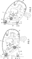
- An awning shown in the drawing comprises a fabric shaft 1 for Rolling up an awning cloth 2, which is supported on support plates 3 on both sides is and via a gear 4 and a pivot 5 with eyelet 6 to Winding and unwinding the awning cloth is driven.
- Support plates 3 On the side Support plates 3 are also the articulated arms 7, which the awning cloth wear, and the outer ends connected to a drop profile 8 are.
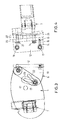
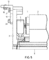
- the support plates 3 of the awning are mounted on holding brackets 9, which have a flange portion 10 which is perpendicular to the house wall mounting plane 11 extends, and have a second flange portion 12 on, which is parallel to the house wall mounting level 11 and perpendicular extends to the first flange section 10.
- This second flange section 12 is provided with two mounting holes 13 and 14, respectively the bore 14 is designed as an elongated hole.
- Perpendicular to this slot 14 extends in the flange portion 12 with a threaded bore 15 an adjusting screw 16, which with its inner end on a Wall mounting screw 17 supports which penetrates the slot 14 and is used for fastening on the building side.
- Another wall mounting screw 18 passes through the upper mounting hole in the drawing 19th
- the first flange section perpendicular to the house wall mounting level 11 10 of each bracket 9 is, in the drawing above, with a hole 20 provided for a screw 21 which a pivot bearing for Forms support plate 3 relative to the first flange portion 10, and which in a threaded bore 20 'engages.
- both slots 22, 23 have one Width that corresponds to the diameter of a locking screw 24 with nut 25 equivalent.
Landscapes
- Engineering & Computer Science (AREA)
- Architecture (AREA)
- Civil Engineering (AREA)
- Structural Engineering (AREA)
- Building Awnings And Sunshades (AREA)
- Tents Or Canopies (AREA)
- Blinds (AREA)
Abstract
Description
- Fig. 1
- eine Seitenansicht einer erfindungsgemäßen Markise von außen,
- Fig. 2
- eine Fig. 1 entsprechende Darstellung mit einer stärker nach unten geneigten Winkeleinstellung,
- Fig. 3
- eine Ansicht einer erfindungsgemäßen Gelenkarm-Markise von außen aus einem gegenüber Fig. 1 um 180° versetzten Blickwinkel,
- Fig. 4
- eine Ansicht des Haltekonsolen-Bereichs von innen und
- Fig. 5
- eine Aufsicht auf den Haltekonsolen-Bereich.
Claims (4)
- Gelenkarm-Markise umfassend zwei Haltekonsolen zur Lagerung der Tuchwelle und der Gelenkarme, wobei jede Haltekonsole wenigstens einen sich senkrecht zur Ebene der Befestigungswand erstreckenden Flanschabschnitt aufweist,
dadurch gekennzeichnet, daßdie Tuchwelle (1) bzw. die Gelenkarme (7) an Tragplatten (3) gelagert sind,die Tragplatten (3) jeweils am Flanschabschnitt (10) der Haltekonsole (9) anliegen,Flanschabschnitt (10) und Tragplatte (3) über ein Schwenklager miteinander verbunden sind,Tragplatte (3) und Flanschabschnitt (10) im Abstand von dem Schwenklager Langlöcher (22, 23) gleicher Breite aufweisen, welche schräg zueinander verlaufen, undeine Feststellschraube (24) mit der Breite der Langlöcher (22, 23) entsprechendem Durchmesser beide Langlöcher durchsetzt und mittels einer der Feststellschraube (24) zugeordneten Feststellmutter (25) die Tragplatte (3) relativ zu dem Flanschabschnitt (10) der Haltekonsole (9) winkeleinstellbar festlegbar ist. - Gelenkarm-Markise nach Anspruch 1,
dadurch gekennzeichnet, daß das Schwenklager durch zwei fluchtende Bohrungen (20, 20') in der Tragplatte (3) bzw. in dem Flanschabschnitt (10) gebildet wird, die von einer Feststellschraube (24) durchsetzt werden. - Gelenkarm-Markise nach Anspruch 1,
dadurch gekennzeichnet, daß jede Haltekonsole einen parallel zur Wandbefestigungsebene verlaufenden zweiten Flanschabschnitt mit Bohrungen für Wandbefestigungsschrauben aufweist. - Gelenkarm-Markise insbesondere nach Anspruch 3,
dadurch gekennzeichnet, daß wenigstens eine der Wandbefestigungs-Bohrungen als Langloch ausgebildet ist, und daß in dem zweiten Flanschabschnitt eine senkrecht zu diesem Langloch verlaufende, in dieses mündende Gewindebohrung mit einer Einstellschraube (16) vorgesehen ist.
Applications Claiming Priority (2)
| Application Number | Priority Date | Filing Date | Title |
|---|---|---|---|
| DE10045582 | 2000-09-15 | ||
| DE10045582A DE10045582C1 (de) | 2000-09-15 | 2000-09-15 | Gelenkarm-Markise |
Publications (3)
| Publication Number | Publication Date |
|---|---|
| EP1188877A2 true EP1188877A2 (de) | 2002-03-20 |
| EP1188877A3 EP1188877A3 (de) | 2003-04-02 |
| EP1188877B1 EP1188877B1 (de) | 2004-04-07 |
Family
ID=7656252
Family Applications (1)
| Application Number | Title | Priority Date | Filing Date |
|---|---|---|---|
| EP01114067A Expired - Lifetime EP1188877B1 (de) | 2000-09-15 | 2001-06-09 | Gelenkarm-Markise |
Country Status (5)
| Country | Link |
|---|---|
| EP (1) | EP1188877B1 (de) |
| CN (1) | CN1174152C (de) |
| AT (1) | ATE263880T1 (de) |
| DE (2) | DE10045582C1 (de) |
| ES (1) | ES2217059T3 (de) |
Families Citing this family (1)
| Publication number | Priority date | Publication date | Assignee | Title |
|---|---|---|---|---|
| DE102008011294B3 (de) * | 2008-02-27 | 2009-06-25 | Schmitz-Werke Gmbh + Co. Kg | Markise mit Sensoranordnung zur Erfassung von Wind- und Wasserlasten |
Family Cites Families (6)
| Publication number | Priority date | Publication date | Assignee | Title |
|---|---|---|---|---|
| DE2359132A1 (de) * | 1973-11-28 | 1975-06-12 | Adolf Merkel Ohg | Aufrollbare markise |
| IT1157789B (it) * | 1982-11-30 | 1987-02-18 | Riri Italia Spa | Armatura con bracci articolati registrabili in pendenza per tende da sole avvolgibili |
| DE8907928U1 (de) * | 1989-06-29 | 1990-10-31 | Robert Schöne KG, 4300 Essen | Konsole für einen Gelenkarm einer Markise |
| DE9102023U1 (de) * | 1991-02-21 | 1992-03-19 | Stobag Ag, Merenschwand | Markise |
| ES2029203A6 (es) * | 1991-03-06 | 1992-07-16 | Magrane Pujol Juan | Perfeccionamientos en la construccion de estructuras en voladizo replegables. |
| DE19644895C2 (de) * | 1996-10-29 | 1999-08-05 | Roedelbronn Gmbh | Kastenmarkise |
-
2000
- 2000-09-15 DE DE10045582A patent/DE10045582C1/de not_active Expired - Fee Related
-
2001
- 2001-06-09 EP EP01114067A patent/EP1188877B1/de not_active Expired - Lifetime
- 2001-06-09 DE DE50101890T patent/DE50101890D1/de not_active Expired - Lifetime
- 2001-06-09 ES ES01114067T patent/ES2217059T3/es not_active Expired - Lifetime
- 2001-06-09 AT AT01114067T patent/ATE263880T1/de active
- 2001-09-14 CN CNB011330309A patent/CN1174152C/zh not_active Expired - Fee Related
Also Published As
| Publication number | Publication date |
|---|---|
| DE10045582C1 (de) | 2002-02-21 |
| ATE263880T1 (de) | 2004-04-15 |
| DE50101890D1 (de) | 2004-05-13 |
| EP1188877A3 (de) | 2003-04-02 |
| ES2217059T3 (es) | 2004-11-01 |
| CN1174152C (zh) | 2004-11-03 |
| EP1188877B1 (de) | 2004-04-07 |
| CN1344853A (zh) | 2002-04-17 |
Similar Documents
| Publication | Publication Date | Title |
|---|---|---|
| EP2873792B1 (de) | Türband | |
| EP0537157B1 (de) | Gelenkarmmarkise | |
| DE69200931T2 (de) | Lenksäulen-Anordnung für ein Kraftfahrzeug. | |
| DE102011015563B4 (de) | Selbsttragende Winkelmutter | |
| EP3681347B1 (de) | Blendenträger und schubkasten | |
| EP4180599A1 (de) | Türband | |
| EP0791715A1 (de) | Scharnier-und Feststellereinheit für aushängbare Kraftwagentüren | |
| EP2345787B1 (de) | Türband für Aluminiumtüren | |
| EP0821118B1 (de) | Gelenkarm-Markise | |
| EP0386342A1 (de) | Flügeltür, insbesondere in einer Duschabtrennung | |
| DE102006050662B3 (de) | Kraftfahrzeugtürscharnier | |
| DE19715496C1 (de) | Justierelement | |
| EP2345786B1 (de) | Türband für Aluminiumtüren | |
| DE20020900U1 (de) | Gardinenstange | |
| CH690591A5 (de) | Halterung für einen Rolladen oder für ein Rolltor. | |
| DE19940010A1 (de) | Antennenträgeranorndung | |
| EP1188877B1 (de) | Gelenkarm-Markise | |
| EP0839971B1 (de) | Kastenmarkise | |
| EP3806695B1 (de) | Schubkasten und verfahren zur montage einer rückwand an einer seitenzarge eines schubkastens | |
| DE10030167A1 (de) | Über mindestens ein Scharnier an einer Fahrzeugkarosserie angelenktes Schwenkteil wie Tür, Klappe oder dergleichen | |
| DE9404976U1 (de) | Drehbeschlag | |
| EP0617191B1 (de) | Führungsschienenanordnung für eine Wintergartenmarkise o. dgl. | |
| DE102020119470B4 (de) | Haltevorrichtung zur lösbaren Festlegung eines Funktionselements an einer Oberfläche | |
| EP1653030B1 (de) | Scharnier mit wenigstens zwei Scharnierteilen zur Anordnung in Zusammenwirken mit einem Trag- und Aufnahmeelement | |
| AT526690B1 (de) | Scharnieranordnung für eine Tür eines Überkopfgepäckfachs |
Legal Events
| Date | Code | Title | Description |
|---|---|---|---|
| PUAI | Public reference made under article 153(3) epc to a published international application that has entered the european phase |
Free format text: ORIGINAL CODE: 0009012 |
|
| AK | Designated contracting states |
Kind code of ref document: A2 Designated state(s): AT BE CH CY DE DK ES FI FR GB GR IE IT LI LU MC NL PT SE TR |
|
| AX | Request for extension of the european patent |
Free format text: AL;LT;LV;MK;RO;SI |
|
| PUAL | Search report despatched |
Free format text: ORIGINAL CODE: 0009013 |
|
| AK | Designated contracting states |
Kind code of ref document: A3 Designated state(s): AT BE CH CY DE DK ES FI FR GB GR IE IT LI LU MC NL PT SE TR |
|
| AX | Request for extension of the european patent |
Extension state: AL LT LV MK RO SI |
|
| 17P | Request for examination filed |
Effective date: 20030308 |
|
| 17Q | First examination report despatched |
Effective date: 20030703 |
|
| GRAP | Despatch of communication of intention to grant a patent |
Free format text: ORIGINAL CODE: EPIDOSNIGR1 |
|
| AKX | Designation fees paid |
Designated state(s): AT BE CH CY DE DK ES FI FR GB GR IE IT LI LU MC NL PT SE TR |
|
| GRAS | Grant fee paid |
Free format text: ORIGINAL CODE: EPIDOSNIGR3 |
|
| GRAA | (expected) grant |
Free format text: ORIGINAL CODE: 0009210 |
|
| AK | Designated contracting states |
Kind code of ref document: B1 Designated state(s): AT BE CH CY DE DK ES FI FR GB GR IE IT LI LU MC NL PT SE TR |
|
| PG25 | Lapsed in a contracting state [announced via postgrant information from national office to epo] |
Ref country code: TR Free format text: LAPSE BECAUSE OF FAILURE TO SUBMIT A TRANSLATION OF THE DESCRIPTION OR TO PAY THE FEE WITHIN THE PRESCRIBED TIME-LIMIT Effective date: 20040407 Ref country code: IE Free format text: LAPSE BECAUSE OF FAILURE TO SUBMIT A TRANSLATION OF THE DESCRIPTION OR TO PAY THE FEE WITHIN THE PRESCRIBED TIME-LIMIT Effective date: 20040407 Ref country code: CY Free format text: LAPSE BECAUSE OF FAILURE TO SUBMIT A TRANSLATION OF THE DESCRIPTION OR TO PAY THE FEE WITHIN THE PRESCRIBED TIME-LIMIT Effective date: 20040407 Ref country code: FI Free format text: LAPSE BECAUSE OF FAILURE TO SUBMIT A TRANSLATION OF THE DESCRIPTION OR TO PAY THE FEE WITHIN THE PRESCRIBED TIME-LIMIT Effective date: 20040407 Ref country code: GB Free format text: LAPSE BECAUSE OF FAILURE TO SUBMIT A TRANSLATION OF THE DESCRIPTION OR TO PAY THE FEE WITHIN THE PRESCRIBED TIME-LIMIT Effective date: 20040407 |
|
| REG | Reference to a national code |
Ref country code: GB Ref legal event code: FG4D Free format text: NOT ENGLISH |
|
| REG | Reference to a national code |
Ref country code: CH Ref legal event code: EP |
|
| REF | Corresponds to: |
Ref document number: 50101890 Country of ref document: DE Date of ref document: 20040513 Kind code of ref document: P |
|
| REG | Reference to a national code |
Ref country code: IE Ref legal event code: FG4D Free format text: GERMAN |
|
| PG25 | Lapsed in a contracting state [announced via postgrant information from national office to epo] |
Ref country code: LU Free format text: LAPSE BECAUSE OF NON-PAYMENT OF DUE FEES Effective date: 20040609 |
|
| PG25 | Lapsed in a contracting state [announced via postgrant information from national office to epo] |
Ref country code: MC Free format text: LAPSE BECAUSE OF NON-PAYMENT OF DUE FEES Effective date: 20040630 |
|
| REG | Reference to a national code |
Ref country code: SE Ref legal event code: TRGR |
|
| PG25 | Lapsed in a contracting state [announced via postgrant information from national office to epo] |
Ref country code: GR Free format text: LAPSE BECAUSE OF FAILURE TO SUBMIT A TRANSLATION OF THE DESCRIPTION OR TO PAY THE FEE WITHIN THE PRESCRIBED TIME-LIMIT Effective date: 20040707 Ref country code: DK Free format text: LAPSE BECAUSE OF FAILURE TO SUBMIT A TRANSLATION OF THE DESCRIPTION OR TO PAY THE FEE WITHIN THE PRESCRIBED TIME-LIMIT Effective date: 20040707 |
|
| GBV | Gb: ep patent (uk) treated as always having been void in accordance with gb section 77(7)/1977 [no translation filed] |
Effective date: 20040407 |
|
| ET | Fr: translation filed | ||
| REG | Reference to a national code |
Ref country code: ES Ref legal event code: FG2A Ref document number: 2217059 Country of ref document: ES Kind code of ref document: T3 |
|
| REG | Reference to a national code |
Ref country code: IE Ref legal event code: FD4D |
|
| PLBE | No opposition filed within time limit |
Free format text: ORIGINAL CODE: 0009261 |
|
| STAA | Information on the status of an ep patent application or granted ep patent |
Free format text: STATUS: NO OPPOSITION FILED WITHIN TIME LIMIT |
|
| 26N | No opposition filed |
Effective date: 20050110 |
|
| PG25 | Lapsed in a contracting state [announced via postgrant information from national office to epo] |
Ref country code: PT Free format text: LAPSE BECAUSE OF NON-PAYMENT OF DUE FEES Effective date: 20040907 |
|
| REG | Reference to a national code |
Ref country code: FR Ref legal event code: PLFP Year of fee payment: 16 |
|
| REG | Reference to a national code |
Ref country code: FR Ref legal event code: PLFP Year of fee payment: 17 |
|
| PGFP | Annual fee paid to national office [announced via postgrant information from national office to epo] |
Ref country code: FR Payment date: 20170621 Year of fee payment: 17 Ref country code: CH Payment date: 20170510 Year of fee payment: 17 |
|
| PGFP | Annual fee paid to national office [announced via postgrant information from national office to epo] |
Ref country code: AT Payment date: 20170516 Year of fee payment: 17 Ref country code: IT Payment date: 20170622 Year of fee payment: 17 Ref country code: SE Payment date: 20170626 Year of fee payment: 17 Ref country code: BE Payment date: 20170621 Year of fee payment: 17 Ref country code: NL Payment date: 20170621 Year of fee payment: 17 |
|
| PGFP | Annual fee paid to national office [announced via postgrant information from national office to epo] |
Ref country code: ES Payment date: 20170703 Year of fee payment: 17 |
|
| PGFP | Annual fee paid to national office [announced via postgrant information from national office to epo] |
Ref country code: DE Payment date: 20180821 Year of fee payment: 18 |
|
| REG | Reference to a national code |
Ref country code: SE Ref legal event code: EUG |
|
| PG25 | Lapsed in a contracting state [announced via postgrant information from national office to epo] |
Ref country code: SE Free format text: LAPSE BECAUSE OF NON-PAYMENT OF DUE FEES Effective date: 20180610 |
|
| REG | Reference to a national code |
Ref country code: CH Ref legal event code: PL |
|
| REG | Reference to a national code |
Ref country code: NL Ref legal event code: MM Effective date: 20180701 |
|
| REG | Reference to a national code |
Ref country code: AT Ref legal event code: MM01 Ref document number: 263880 Country of ref document: AT Kind code of ref document: T Effective date: 20180609 |
|
| REG | Reference to a national code |
Ref country code: BE Ref legal event code: MM Effective date: 20180630 |
|
| PG25 | Lapsed in a contracting state [announced via postgrant information from national office to epo] |
Ref country code: NL Free format text: LAPSE BECAUSE OF NON-PAYMENT OF DUE FEES Effective date: 20180701 |
|
| PG25 | Lapsed in a contracting state [announced via postgrant information from national office to epo] |
Ref country code: LI Free format text: LAPSE BECAUSE OF NON-PAYMENT OF DUE FEES Effective date: 20180630 Ref country code: IT Free format text: LAPSE BECAUSE OF NON-PAYMENT OF DUE FEES Effective date: 20180609 Ref country code: CH Free format text: LAPSE BECAUSE OF NON-PAYMENT OF DUE FEES Effective date: 20180630 Ref country code: AT Free format text: LAPSE BECAUSE OF NON-PAYMENT OF DUE FEES Effective date: 20180609 Ref country code: FR Free format text: LAPSE BECAUSE OF NON-PAYMENT OF DUE FEES Effective date: 20180630 |
|
| PG25 | Lapsed in a contracting state [announced via postgrant information from national office to epo] |
Ref country code: BE Free format text: LAPSE BECAUSE OF NON-PAYMENT OF DUE FEES Effective date: 20180630 |
|
| REG | Reference to a national code |
Ref country code: ES Ref legal event code: FD2A Effective date: 20190916 |
|
| PG25 | Lapsed in a contracting state [announced via postgrant information from national office to epo] |
Ref country code: ES Free format text: LAPSE BECAUSE OF NON-PAYMENT OF DUE FEES Effective date: 20180610 |
|
| REG | Reference to a national code |
Ref country code: DE Ref legal event code: R119 Ref document number: 50101890 Country of ref document: DE |
|
| PG25 | Lapsed in a contracting state [announced via postgrant information from national office to epo] |
Ref country code: DE Free format text: LAPSE BECAUSE OF NON-PAYMENT OF DUE FEES Effective date: 20200101 |