EP1188933B1 - Steuervorrichtung für verstellbare Leitschaufeln - Google Patents
Steuervorrichtung für verstellbare Leitschaufeln Download PDFInfo
- Publication number
- EP1188933B1 EP1188933B1 EP01402379A EP01402379A EP1188933B1 EP 1188933 B1 EP1188933 B1 EP 1188933B1 EP 01402379 A EP01402379 A EP 01402379A EP 01402379 A EP01402379 A EP 01402379A EP 1188933 B1 EP1188933 B1 EP 1188933B1
- Authority
- EP
- European Patent Office
- Prior art keywords
- rod
- pivot
- blade
- ring
- control ring
- Prior art date
- Legal status (The legal status is an assumption and is not a legal conclusion. Google has not performed a legal analysis and makes no representation as to the accuracy of the status listed.)
- Expired - Lifetime
Links
- 239000002184 metal Substances 0.000 claims description 8
- 229920001971 elastomer Polymers 0.000 claims description 6
- 239000000806 elastomer Substances 0.000 claims description 6
- 238000004519 manufacturing process Methods 0.000 description 4
- KAKZBPTYRLMSJV-UHFFFAOYSA-N Butadiene Chemical compound C=CC=C KAKZBPTYRLMSJV-UHFFFAOYSA-N 0.000 description 2
- 239000002131 composite material Substances 0.000 description 2
- 238000005520 cutting process Methods 0.000 description 2
- 230000005489 elastic deformation Effects 0.000 description 2
- BRLQWZUYTZBJKN-UHFFFAOYSA-N Epichlorohydrin Chemical compound ClCC1CO1 BRLQWZUYTZBJKN-UHFFFAOYSA-N 0.000 description 1
- 244000043261 Hevea brasiliensis Species 0.000 description 1
- 229910000831 Steel Inorganic materials 0.000 description 1
- 238000005452 bending Methods 0.000 description 1
- 230000005540 biological transmission Effects 0.000 description 1
- YACLQRRMGMJLJV-UHFFFAOYSA-N chloroprene Chemical compound ClC(=C)C=C YACLQRRMGMJLJV-UHFFFAOYSA-N 0.000 description 1
- 230000008094 contradictory effect Effects 0.000 description 1
- 238000002788 crimping Methods 0.000 description 1
- 230000032798 delamination Effects 0.000 description 1
- 238000006073 displacement reaction Methods 0.000 description 1
- 230000000694 effects Effects 0.000 description 1
- 230000007613 environmental effect Effects 0.000 description 1
- 239000011888 foil Substances 0.000 description 1
- 238000009434 installation Methods 0.000 description 1
- 238000000034 method Methods 0.000 description 1
- 230000004048 modification Effects 0.000 description 1
- 238000012986 modification Methods 0.000 description 1
- 229920003052 natural elastomer Polymers 0.000 description 1
- 229920001194 natural rubber Polymers 0.000 description 1
- 150000002825 nitriles Chemical class 0.000 description 1
- 229920001296 polysiloxane Polymers 0.000 description 1
- 239000007787 solid Substances 0.000 description 1
- 229910001220 stainless steel Inorganic materials 0.000 description 1
- 239000010935 stainless steel Substances 0.000 description 1
- 239000010959 steel Substances 0.000 description 1
- 230000001360 synchronised effect Effects 0.000 description 1
Images


Classifications
-
- F—MECHANICAL ENGINEERING; LIGHTING; HEATING; WEAPONS; BLASTING
- F01—MACHINES OR ENGINES IN GENERAL; ENGINE PLANTS IN GENERAL; STEAM ENGINES
- F01D—NON-POSITIVE DISPLACEMENT MACHINES OR ENGINES, e.g. STEAM TURBINES
- F01D17/00—Regulating or controlling by varying flow
- F01D17/10—Final actuators
- F01D17/12—Final actuators arranged in stator parts
- F01D17/14—Final actuators arranged in stator parts varying effective cross-sectional area of nozzles or guide conduits
- F01D17/16—Final actuators arranged in stator parts varying effective cross-sectional area of nozzles or guide conduits by means of nozzle vanes
-
- F—MECHANICAL ENGINEERING; LIGHTING; HEATING; WEAPONS; BLASTING
- F01—MACHINES OR ENGINES IN GENERAL; ENGINE PLANTS IN GENERAL; STEAM ENGINES
- F01D—NON-POSITIVE DISPLACEMENT MACHINES OR ENGINES, e.g. STEAM TURBINES
- F01D17/00—Regulating or controlling by varying flow
- F01D17/10—Final actuators
- F01D17/12—Final actuators arranged in stator parts
- F01D17/14—Final actuators arranged in stator parts varying effective cross-sectional area of nozzles or guide conduits
- F01D17/16—Final actuators arranged in stator parts varying effective cross-sectional area of nozzles or guide conduits by means of nozzle vanes
- F01D17/162—Final actuators arranged in stator parts varying effective cross-sectional area of nozzles or guide conduits by means of nozzle vanes for axial flow, i.e. the vanes turning around axes which are essentially perpendicular to the rotor centre line
-
- F—MECHANICAL ENGINEERING; LIGHTING; HEATING; WEAPONS; BLASTING
- F04—POSITIVE - DISPLACEMENT MACHINES FOR LIQUIDS; PUMPS FOR LIQUIDS OR ELASTIC FLUIDS
- F04D—NON-POSITIVE-DISPLACEMENT PUMPS
- F04D29/00—Details, component parts, or accessories
- F04D29/40—Casings; Connections of working fluid
- F04D29/52—Casings; Connections of working fluid for axial pumps
- F04D29/54—Fluid-guiding means, e.g. diffusers
- F04D29/56—Fluid-guiding means, e.g. diffusers adjustable
- F04D29/563—Fluid-guiding means, e.g. diffusers adjustable specially adapted for elastic fluid pumps
-
- Y—GENERAL TAGGING OF NEW TECHNOLOGICAL DEVELOPMENTS; GENERAL TAGGING OF CROSS-SECTIONAL TECHNOLOGIES SPANNING OVER SEVERAL SECTIONS OF THE IPC; TECHNICAL SUBJECTS COVERED BY FORMER USPC CROSS-REFERENCE ART COLLECTIONS [XRACs] AND DIGESTS
- Y02—TECHNOLOGIES OR APPLICATIONS FOR MITIGATION OR ADAPTATION AGAINST CLIMATE CHANGE
- Y02T—CLIMATE CHANGE MITIGATION TECHNOLOGIES RELATED TO TRANSPORTATION
- Y02T50/00—Aeronautics or air transport
- Y02T50/60—Efficient propulsion technologies, e.g. for aircraft
-
- Y—GENERAL TAGGING OF NEW TECHNOLOGICAL DEVELOPMENTS; GENERAL TAGGING OF CROSS-SECTIONAL TECHNOLOGIES SPANNING OVER SEVERAL SECTIONS OF THE IPC; TECHNICAL SUBJECTS COVERED BY FORMER USPC CROSS-REFERENCE ART COLLECTIONS [XRACs] AND DIGESTS
- Y10—TECHNICAL SUBJECTS COVERED BY FORMER USPC
- Y10T—TECHNICAL SUBJECTS COVERED BY FORMER US CLASSIFICATION
- Y10T403/00—Joints and connections
- Y10T403/32—Articulated members
- Y10T403/32008—Plural distinct articulation axes
- Y10T403/32057—Angular and linear
- Y10T403/32073—Pivot stud slidable in elongated opening
-
- Y—GENERAL TAGGING OF NEW TECHNOLOGICAL DEVELOPMENTS; GENERAL TAGGING OF CROSS-SECTIONAL TECHNOLOGIES SPANNING OVER SEVERAL SECTIONS OF THE IPC; TECHNICAL SUBJECTS COVERED BY FORMER USPC CROSS-REFERENCE ART COLLECTIONS [XRACs] AND DIGESTS
- Y10—TECHNICAL SUBJECTS COVERED BY FORMER USPC
- Y10T—TECHNICAL SUBJECTS COVERED BY FORMER US CLASSIFICATION
- Y10T403/00—Joints and connections
- Y10T403/32—Articulated members
- Y10T403/32114—Articulated members including static joint
- Y10T403/32163—Articulate joint intermediate end joints
- Y10T403/32172—Variable angle
-
- Y—GENERAL TAGGING OF NEW TECHNOLOGICAL DEVELOPMENTS; GENERAL TAGGING OF CROSS-SECTIONAL TECHNOLOGIES SPANNING OVER SEVERAL SECTIONS OF THE IPC; TECHNICAL SUBJECTS COVERED BY FORMER USPC CROSS-REFERENCE ART COLLECTIONS [XRACs] AND DIGESTS
- Y10—TECHNICAL SUBJECTS COVERED BY FORMER USPC
- Y10T—TECHNICAL SUBJECTS COVERED BY FORMER US CLASSIFICATION
- Y10T403/00—Joints and connections
- Y10T403/50—Bridged by diverse connector
-
- Y—GENERAL TAGGING OF NEW TECHNOLOGICAL DEVELOPMENTS; GENERAL TAGGING OF CROSS-SECTIONAL TECHNOLOGIES SPANNING OVER SEVERAL SECTIONS OF THE IPC; TECHNICAL SUBJECTS COVERED BY FORMER USPC CROSS-REFERENCE ART COLLECTIONS [XRACs] AND DIGESTS
- Y10—TECHNICAL SUBJECTS COVERED BY FORMER USPC
- Y10T—TECHNICAL SUBJECTS COVERED BY FORMER US CLASSIFICATION
- Y10T403/00—Joints and connections
- Y10T403/54—Flexible member is joint component
-
- Y—GENERAL TAGGING OF NEW TECHNOLOGICAL DEVELOPMENTS; GENERAL TAGGING OF CROSS-SECTIONAL TECHNOLOGIES SPANNING OVER SEVERAL SECTIONS OF THE IPC; TECHNICAL SUBJECTS COVERED BY FORMER USPC CROSS-REFERENCE ART COLLECTIONS [XRACs] AND DIGESTS
- Y10—TECHNICAL SUBJECTS COVERED BY FORMER USPC
- Y10T—TECHNICAL SUBJECTS COVERED BY FORMER US CLASSIFICATION
- Y10T403/00—Joints and connections
- Y10T403/55—Member ends joined by inserted section
- Y10T403/551—Externally bridged
Definitions
- the present invention relates to the control of blades variable pitch angle. It finds a particular application in the field of aeronautics, in particular for the control of the angular positions of air inlet guide vanes in turbomachine compressors, such as turbojet engines or turboprop aircraft engines.
- Known devices for controlling variable pitch vanes in a turbomachine usually comprise a control member in the form of a ring surrounding a casing of the turbomachine and a plurality of levers, or rods, each rod having a first end connected to the control ring by a hinge and a second end mounted on a pivot of a respective blade.
- the synchronized modification of the angular position of the blades is made by rotation of the ring around the axis of the turbomachine.
- the connection between each link and the ring comprises at least one degree of freedom in rotation about an axis directed substantially radially relative to the ring.
- the link being rigidly mounted on the pivot of the corresponding blade, the rotation of the ring induces other relative movements between the ring and the portion of the rod mounted on the pivot of the blade.
- connection in the form of a ball or a similar part which, in addition to the rotation around a substantially radial axis relative to the ring, allows rotation about an axis having a substantially circumferential direction relative to the ring. It has also been proposed to provide a link providing an additional degree of freedom in translation in a substantially radial direction relative to the ring. It will be possible, among other things, to refer to the documents FR-A-2,608,678 or FR-A-2,746,141 , US-A-2 999630 .
- the elastic deformation capacity is given by a thinning of the rod in its central part, between the ends connected to the control ring and a pivot of a blade.
- it is necessary to provide sufficient flexibility not to impede the transmission of movement between the control ring and the blades and, on the other hand, it must maintain a link thickness sufficient to withstand fatigue and avoid the risk of buckling. The best compromise between these contradictory requirements is difficult to find.
- the object of the invention is to avoid the disadvantages of the devices of the prior art by proposing a control device using a flexible link which has a very high resistance to mechanical fatigue caused by repeated actuations and a high resistance to buckling. while having a flexibility allowing it to easily deform in torsion, throughout the range of rotation of the control ring.
- Another object of the invention is to provide a device that allows to simplify its assembly and also allow quick and easy individual disassembly of these rods.
- Yet another object of the invention is to propose a device having a particularly reduced hysteresis at the level of the blade / link connection.
- a device of the type comprising a connecting rod, connecting means forming an articulation between a first end of the connecting rod and a control ring, and means for fixing a second end of the link on a pivot.
- a blade to be controlled a device in which, according to the invention, said connecting means comprise a pivot passing through a first orifice pierced in said first end of the rod and engaged in a radial housing of said control ring, said pivot being held in position by a locking ring provided with windows (36) for the passage of this pivot and sliding on said control ring, said fixing means comprise a fixing screw passing through a second orifice pierced in said second end of the link and introduced into a hole of said pivot of the blade to be controlled, and said device further comprises means for maintaining in rotation without play said link on said blade pivot.
- the assembly / disassembly of the device is greatly facilitated due to the one-piece nature (obtained by the presence of the locking ring) of the control ring and rods assembly, and on the other hand, the individual replacement of the links, without disassembly of the control ring, is made particularly easy.
- the automatic play catch-up in the link-aub link makes it possible to avoid, or at least to reduce considerably, any hysteresis.
- said play-free holding means comprise a radial groove formed in said blade pivot and whose width is smaller than that of said second end of the link that it is intended to receive.
- said link is advantageously arched around its longitudinal axis.
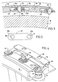
- said play-free holding means comprise at least one tenon formed in said blade pivot and intended to cooperate with tabs cut in said second end of the link. This cutting of the tabs preferably has a configuration in accordance with the figure 9 .
- said rod has, at its second end, a portion having a width greater than that of its first end and to which it is gradually connected.
- said radial housing is delimited by a fur fixed in said first port of the link.
- an abutment interposed between said second end of the rod and said fixing screw.
- said link is constituted by a laminated structure comprising thin rigid layers formed by metal sheets, alternating with elastomer layers, the layers adhering to each other.
- the presence of a laminated structure gives the rod a remarkable behavior. Due to the thinness of the metal layers, linked together by elastomer layers, the rod is easily deformable in bending and twisting. In addition, there is no significant variation in deformation resistance over the entire operating range of the control ring. The control of the padding of the blades is thus precise and easy. In addition, despite their thinness, the metal layers form with the elastomer layers an assembly having a very high resistance to fatigue and buckling.
- said control and locking rings are each made in two parts each extending over 180 ° of the circumference of the turbomachine.
- FIGS. 1 to 3 illustrate in section and the figure 4 in perspective a portion of a turbomachine, turbojet or turboprop aircraft or any other terrestrial or marine power generator, for example one of the guide vanes distributed around the axis of the turbomachine and placed at the compressor inlet.
- This blade 10 is of the blade type variable pitch angle.
- Each blade 10 is provided with a blade pivot 12 with axis 14 which can rotate inside a smooth bearing defined by a ring 16a, 16b passing through a body portion 18 of the turbomachine (in this case an outer shell or the rectifier housing).
- each blade 10 is caused by a flexible link 20 (illustrated in FIG. figure 5 ) preferably comprising a flexible composite structure such as a laminated structure consisting of thin metal layers alternating with elastomer layers, the layers adhering to each other.
- the metal layers are formed by metal sheets of thickness preferably less than 0.5 mm, cut into strips or foils for example steel, stainless steel, or any other metal suitable for the intended application.
- the elastomer layers are formed for example of natural rubber, chloroprene, butadiene, nitrile, epichlorohydrin, silicone, etc., the choice being made according to the desired mechanical characteristics and environmental conditions.
- the rod 20 includes a first port 22 for receiving connecting means formed by a pivot 24 of axis 26 engaged in a radial housing 28 of a control ring 30.
- This housing is advantageously delimited by a fur 32 (set of two crimped parts, a sleeve 32 and a ring 32 b) mounted in the first orifice 22 formed through the link 20 and intended firstly to compensate for the clearance between the rod and the control ring and secondly to provide a sufficient centering length to resume the efforts of the pivot 24.
- the pivot is maintained in position by a locking ring 34 sliding on the control ring and provided with windows 36 of shape corresponding to that of this pivot (or more precisely of its head).
- the rod 20 comprises a second orifice 38 for receiving fastening means formed by a fastening screw 40 engaged in a threaded blind hole 42 of the pivot of the blade 12.
- This rod is made integral in rotation of the pivot 12 and held without play in the blade pivot being engaged in a radial groove 44, of smaller width than that of the rod, formed in this pivot and releasing a seat 44 has for the rod and two radial edges of positioning plates 44 b, 44 c ( figures 2 and 4 ).
- a stop washer 46 is interposed between the end 20b of the rod and the fixing screw 40.
- the control ring 30, whose axis coincides with the longitudinal axis of the turbomachine, is rotatable about its axis. It comprises a plurality of lumens 48, in number equal to that of the vanes, radially drilled and of a width substantially greater than that of a connecting rod. Preferably, it is made in two parts (2 half-ring) each covering 180 ° of the circumference of the turbomachine. These parts are connected (locked) to each other by a linking ferrule (not shown). The rotational drive is typically provided by one or more cylinders (not shown). The rotation of the control ring makes it possible to vary the angular position of the vanes 10 via the rods 20. Similarly, the locking ring 34 is formed in two parts each also covering 180 °. A unique set of 360 ° is of course possible according to the architecture of the turbomachine.
- the assembly / disassembly of the blades will now be illustrated next to the figure 6 .
- the assembly is essentially done in two stages.
- a first step which can be carried out separately in the workshop (this is one of the important advantages of the invention), consists in individually mounting all the links 20 on the control ring 30 and locking them by the ring. lock 34.
- the coat 32 is mounted by crimping (other techniques could be used for fixing the ring 32 b on the sleeve 32 a) in the first port 22 of the link then the assembly is introduced through the lumen 48 of the control ring 30.
- the pin 24 is then introduced through window 36 of the locking ring 34 and fixed to the end 20a of the rod by a simple introduction of this pivot in the fur 32.
- the second step then consists, this time directly on site, to mount the entire assembly thus formed directly on the various pivots 12 of the blades 10.
- the ends 20 b of the rods are placed one by one on the seat 44 a of this pivot and each fixed thereto by the fixing screw 40 via the thrust washer 46.
- the clamping of the thrust washer 46 by the fixing screw 40 keeps the layers of the laminated structure gripped and avoids a untimely takeoff (delamination) at the inner wall of the second orifice 38.
- the establishment of the pivot 24 at the other end of the rod produces the same effect at the inner wall of the first orifice 22.
- the connecting rod 20 has a flat width slightly greater than that of the groove 44 between its flat edges 44 c, 44 d.
- the rod will be advantageously arched (around its longitudinal axis) during its manufacture to obtain an arrow "f" as illustrated above on the figure 2 .
- Disassembly is done in exactly the opposite way. However, and this is another essential advantage of the invention, with the structure described, it is possible to proceed to an individual disassembly of each link. It is sufficient, first of all to disassemble its fixing 40, 46, and then to match the windows 36 of the locking ring 34 with the pivots 24 (of course after unlocking this ring) and to extract the pivot 24 corresponding to the link 20 to be changed, and finally to release the link by the light 48 of the control ring 30. A new rod can therefore be replaced simply by proceeding in the opposite way.
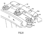
- FIGS 7 to 9 illustrate a second embodiment of the invention according to which the link also has a laminated structure but with a different geometry.
- the second end portion 20b intended to be connected with the blade pivot 12 has a width greater than that of the opposite end 20a to which it is gradually connected and, on the other hand on the other hand, the second orifice 38 has a specific, non-circular cutout, visible particularly on the figure 9 and intended to perform a centering, on the one hand, and a guide, on the other hand, the rod with the blade pivot.
- the central zone is intended to ensure the centering of the fixing screw 40 whose axis fits perfectly in this rectangular area and the legs a folded against the pins under the action of the fixing screw and the thrust washer 46 provide guidance with an automatic adjustment of the clearance between the rod and the blade pivot.
- FIG 7 is a sectional view showing the attachment of the rod at its second end 20b , before and after the establishment of the fixing screw 40.
- the elements according to the first embodiment have the same references. Deformation action can be noted exerted by the pin 54 b on the tabs 52 c, 52 d of the rod 20 which allows a perfect fit without play of said link.
- figure 8 illustrates in perspective at three different stages the connection of the blade with the control ring. Note here again the presence of the tenons directed radially to the upper part of the pivot of the blade.
- the assembly / disassembly of the rods globally or individually is carried out as in the previous embodiment and should be referred to.
- a flexible composite structure such as a laminated structure is particularly advantageous because it combines flexibility and mechanical strength throughout the operating range.
- An interesting feature lies in the fact that the resistance to torsional deformation does not vary significantly in this range, so that the control of the wedging of the blades can be achieved precisely.
Landscapes
- Engineering & Computer Science (AREA)
- Mechanical Engineering (AREA)
- General Engineering & Computer Science (AREA)
- Structures Of Non-Positive Displacement Pumps (AREA)
- Control Of Turbines (AREA)
Claims (12)
- Vorrichtung zur Steuerung einer Schaufel mit variable Einstellwinkel in einer Turbomaschine, mit:einem Schwingarm (20),einem Verstellring (30),einem Schaufeldrehzapfen (12) einer zu steuernden Schaufel,Verbindungsmitteln (24, 32), die ein Gelenk zwischen einem ersten Ende (20a) des Schwingarms und dem Verstellring bilden und die einen Drehzapfen (24) umfassen, der eine in dem ersten Ende des Schwingarms ausgebildete erste Öffnung (22) durchgreift und in eine radiale Aufnahme (28) des Verstellrings eingesteckt ist,und Mitteln (40, 44, 46; 52, 54), um ein zweites Ende (20b) des Schwingarms zu befestigen und spielfrei drehfest zu halten,dadurch gekennzeichnet, daß der Drehzapfen (24) durch einen Verriegelungsring (34), der mit Aussparungen (36) für den Durchgang dieses Drehzapfens ausgestattet ist und auf dem Verstellring gleitet, in Position gehalten wird, unddaß die Befestigungsmittel eine Befestigungsschraube (40) umfassen, die eine in dem zweiten Ende des Schwingarms ausgebildete zweite Öffnung (38) durchgreift, um in ein Loch des Schaufeldrehzapfens eingeführt zu werden.
- Vorrichtung nach Anspruch 1, dadurch gekennzeichnet, daß der Schwingarm um seine Längsachse gebogen ist.
- Vorrichtung nach Anspruch 2, dadurch gekennzeichnet, daß der Schaufeldrehzapfen eine Radialnut (44) aufweist, deren Breite geringer ist als die des zweiten Endes des Schwingarms, das sie aufnehmen soll.
- Vorrichtung nach Anspruch 1, dadurch gekennzeichnet, daß der Schwingarm Laschen (52a, 52b; 52c, 52d) aufweist, die aus dem zweiten Ende des Schwingarms ausgeschnitten sind.
- Vorrichtung nach Anspruch 4, dadurch gekennzeichnet, daß der Schaufeldrehzapfen wenigstens eine Nase (54a und 54b) aufweist, die dazu bestimmt ist, mit den aus dem zweiten Ende des Schwingarms ausgeschnittenen Laschen zusammenzuwirken.
- Vorrichtung nach Anspruch 3, dadurch gekennzeichnet, daß der die Laschen umgebende Ausschnitt auf beiden Seiten einer Mittellängsachse des Schwingarms sowie auf beiden Seiten eines im wesentlichen rechteckigen mittleren Bereichs (50), welcher dazu bestimmt ist, ein Zentrieren der Befestigungsschraube zu gewährleisten, gebildet ist.
- Vorrichtung nach Anspruch 6, dadurch gekennzeichnet, daß der Schwingarm im Bereich seines zweiten Endes (20b) einen Teil aufweist, der breiter ist als sein erstes Ende (20a) und an den es sich nach und nach anschließt.
- Vorrichtung nach Anspruch 1, dadurch gekennzeichnet, daß die radiale Aufnahme durch ein in der ersten Öffnung des Schwingarms befestigtes Futter (32a, 32b) begrenzt ist.
- Vorrichtung nach Anspruch 1, dadurch gekennzeichnet, daß die Befestigungsmittel ferner einen Anschlag (46) umfassen, der zwischen dem zweiten Ende des Schwingarms und der Befestigungsschraube eingefügt ist.
- Vorrichtung nach Anspruch 1, dadurch gekennzeichnet, daß der Schwingarm aus einer Schichtstruktur besteht, die dünne, starre, von Metallfolien gebildete Schichten aufweist, die sich mit Elastomerschichten abwechseln, wobei die Schichten aneinander haften.
- Vorrichtung nach irgendeinem der Ansprüche 1 bis 10, dadurch gekennzeichnet, daß der Verstellring und der Verriegelungsring jeweils aus zwei Teilen gefertigt sind, die sich jeweils über 180° des Umfangs der Turbomaschine erstrecken.
- Turbomaschine mit einer Vorrichtung zur Steuerung einer Schaufel mit variablem Einstellwinkel nach irgendeinem der Ansprüche 1 bis 11.
Applications Claiming Priority (2)
| Application Number | Priority Date | Filing Date | Title |
|---|---|---|---|
| FR0011857 | 2000-09-18 | ||
| FR0011857A FR2814206B1 (fr) | 2000-09-18 | 2000-09-18 | Dispositif de commande d'aubes a calage variable |
Publications (2)
| Publication Number | Publication Date |
|---|---|
| EP1188933A1 EP1188933A1 (de) | 2002-03-20 |
| EP1188933B1 true EP1188933B1 (de) | 2008-09-10 |
Family
ID=8854395
Family Applications (1)
| Application Number | Title | Priority Date | Filing Date |
|---|---|---|---|
| EP01402379A Expired - Lifetime EP1188933B1 (de) | 2000-09-18 | 2001-09-17 | Steuervorrichtung für verstellbare Leitschaufeln |
Country Status (9)
| Country | Link |
|---|---|
| US (1) | US6688846B2 (de) |
| EP (1) | EP1188933B1 (de) |
| JP (1) | JP4643077B2 (de) |
| CA (1) | CA2357174C (de) |
| DE (1) | DE60135717D1 (de) |
| ES (1) | ES2312409T3 (de) |
| FR (1) | FR2814206B1 (de) |
| RU (1) | RU2272913C2 (de) |
| UA (1) | UA72753C2 (de) |
Families Citing this family (30)
| Publication number | Priority date | Publication date | Assignee | Title |
|---|---|---|---|---|
| FR2835294B1 (fr) * | 2002-01-29 | 2004-04-16 | Snecma Moteurs | Dispositif de commande d'aube a angle de calage variable a liaison sans jeu |
| FR2835295B1 (fr) * | 2002-01-29 | 2004-04-16 | Snecma Moteurs | Dispositif de commande d'aube a angle de calage variable a liaison par pincement pour redresseur de compresseur de turbomachine |
| FR2854648B1 (fr) * | 2003-05-07 | 2005-07-15 | Snecma Moteurs | Fixation avec rattrapage de jeu d'un levier de commande sur des aubes a angle de calage variable |
| FR2866058B1 (fr) * | 2004-02-05 | 2006-06-02 | Snecma Moteurs | Levier de commande du calage angulaire d'une aube dans une turbomachine |
| FR2879687B1 (fr) * | 2004-12-16 | 2007-04-20 | Snecma Moteurs Sa | Turbomachine a stator comportant un etage d'aubes de redresseur actionnees par une couronne rotative deplacee par des moyens moteurs electriques |
| US7628579B2 (en) * | 2005-07-20 | 2009-12-08 | United Technologies Corporation | Gear train variable vane synchronizing mechanism for inner diameter vane shroud |
| US7753647B2 (en) * | 2005-07-20 | 2010-07-13 | United Technologies Corporation | Lightweight cast inner diameter vane shroud for variable stator vanes |
| US7588415B2 (en) * | 2005-07-20 | 2009-09-15 | United Technologies Corporation | Synch ring variable vane synchronizing mechanism for inner diameter vane shroud |
| US7690889B2 (en) * | 2005-07-20 | 2010-04-06 | United Technologies Corporation | Inner diameter variable vane actuation mechanism |
| US7722318B2 (en) * | 2007-02-13 | 2010-05-25 | United Technologies Corporation | Hole liners for repair of vane counterbore holes |
| CN101743379A (zh) * | 2007-04-10 | 2010-06-16 | 艾利奥特公司 | 具有可调进口导向叶片的离心式压缩机 |
| US8033782B2 (en) * | 2008-01-16 | 2011-10-11 | Elliott Company | Method to prevent brinelling wear of slot and pin assembly |
| US8215902B2 (en) * | 2008-10-15 | 2012-07-10 | United Technologies Corporation | Scalable high pressure compressor variable vane actuation arm |
| FR2947310B1 (fr) * | 2009-06-26 | 2014-08-29 | Snecma | Dispositif et methode de positionnement d'un equipement a geometrie variable pour une turbomachine, utilisant un verin a mesure relative. |
| FR2947311B1 (fr) * | 2009-06-26 | 2014-08-29 | Snecma | Procede et dispositif de recalage de la commande d'un equipement a geometrie variable pour turbomachine |
| FR2963384B1 (fr) | 2010-07-30 | 2012-08-31 | Turbomeca | Dispositif de commande d'aubes pivotantes de turbomachine |
| US10161407B2 (en) | 2013-06-14 | 2018-12-25 | United Technologies Corporation | Radial fastening of tubular synchronizing rings |
| FR3014152B1 (fr) * | 2013-11-29 | 2015-12-25 | Snecma | Dispositif de guidage d'aubes de redresseur a angle de calage variable de turbomachine et procede d'assemblage d'un tel dispositif |
| WO2015088936A1 (en) | 2013-12-11 | 2015-06-18 | United Technologies Corporation | Variable vane positioning apparatus for a gas turbine engine |
| US9970315B2 (en) * | 2015-02-12 | 2018-05-15 | Hamilton Sundstrand Corporation | Movable vane control system |
| CN105135994B (zh) * | 2015-05-15 | 2017-11-21 | 中国航空工业集团公司沈阳发动机设计研究所 | 一种用于压气机可调静子叶片角度标定的测具 |
| US10352186B2 (en) * | 2016-01-22 | 2019-07-16 | United Technologies Corporation | Variable vane stabilizer |
| US10393145B2 (en) | 2016-03-02 | 2019-08-27 | General Electric Company | Asymmetric alignment system for a variable stator vane |
| DE102016207212A1 (de) * | 2016-04-28 | 2017-11-02 | MTU Aero Engines AG | Leitschaufelkranz für eine Strömungsmaschine |
| FR3053383B1 (fr) | 2016-07-04 | 2019-08-02 | Safran Aircraft Engines | Clinquant de retention de douilles d'anneaux de commande d'aubes a calage variable et turboreacteur l'incorporant |
| US10563670B2 (en) | 2016-07-29 | 2020-02-18 | Rolls-Royce Corporation | Vane actuation system for a gas turbine engine |
| WO2019245549A1 (en) * | 2018-06-20 | 2019-12-26 | Siemens Energy, Inc. | Anti-rotation locking system |
| FR3100272B1 (fr) * | 2019-08-27 | 2025-04-25 | Safran Aircraft Engines | Guignol pour un dispositif de calage variable d’une turbomachine |
| CN112324713B (zh) * | 2020-11-26 | 2022-03-22 | 沈阳航空航天大学 | 一种轴流式压气机气流转角自适应导向叶片及其设计方法 |
| CN113898419A (zh) * | 2021-10-10 | 2022-01-07 | 中国航发沈阳发动机研究所 | 一种进气机匣结构及其组装方法 |
Family Cites Families (17)
| Publication number | Priority date | Publication date | Assignee | Title |
|---|---|---|---|---|
| BE496713A (de) * | 1949-07-01 | |||
| US2842305A (en) * | 1955-11-01 | 1958-07-08 | Gen Electric | Compressor stator assembly |
| US2999630A (en) * | 1957-08-08 | 1961-09-12 | Gen Electric | Compressor |
| US3788763A (en) * | 1972-11-01 | 1974-01-29 | Gen Motors Corp | Variable vanes |
| DE2810240C2 (de) * | 1978-03-09 | 1985-09-26 | MTU Motoren- und Turbinen-Union München GmbH, 8000 München | Verstelleitgitter für axial durchströmte Turbinen, insbesondere Hochdruckturbinen von Gasturbinentriebwerken |
| JPS5746325A (en) | 1980-08-30 | 1982-03-16 | Tdk Corp | Magnetic recording medium |
| US4498790A (en) * | 1983-11-21 | 1985-02-12 | United Technologies Corporation | Bushing securing apparatus |
| FR2583817B1 (fr) * | 1985-06-20 | 1988-07-29 | Snecma | Biellette de commande d'aube a calage variable de stator de compresseur de turbomachine |
| US4808069A (en) * | 1986-07-03 | 1989-02-28 | The United States Of America As Represented By The Secretary Of The Air Force | Anti-rotation guide vane bushing |
| FR2608678B1 (fr) | 1986-12-17 | 1991-02-08 | Snecma | Dispositif de commande d'aubes a calage variable de redresseur de turbomachine |
| US4792277A (en) * | 1987-07-08 | 1988-12-20 | United Technologies Corporation | Split shroud compressor |
| GB8913988D0 (en) * | 1989-06-17 | 1989-08-09 | Rolls Royce Plc | Improvements in or relating to control of variable stator vanes |
| US4979874A (en) | 1989-06-19 | 1990-12-25 | United Technologies Corporation | Variable van drive mechanism |
| RU2117826C1 (ru) * | 1995-03-27 | 1998-08-20 | Акционерное общество открытого типа "А.Люлька-Сатурн" | Статор компрессора газотурбинного двигателя |
| US5601401A (en) * | 1995-12-21 | 1997-02-11 | United Technologies Corporation | Variable stage vane actuating apparatus |
| FR2746141B1 (fr) | 1996-03-14 | 1998-04-17 | Dispositif de commande pour pivot integre dans un collecteur | |
| US6019574A (en) * | 1998-08-13 | 2000-02-01 | General Electric Company | Mismatch proof variable stator vane |
-
2000
- 2000-09-18 FR FR0011857A patent/FR2814206B1/fr not_active Expired - Fee Related
-
2001
- 2001-09-10 JP JP2001272957A patent/JP4643077B2/ja not_active Expired - Fee Related
- 2001-09-12 CA CA002357174A patent/CA2357174C/fr not_active Expired - Fee Related
- 2001-09-12 RU RU2001124884/06A patent/RU2272913C2/ru not_active IP Right Cessation
- 2001-09-14 UA UA2001096327A patent/UA72753C2/uk unknown
- 2001-09-17 EP EP01402379A patent/EP1188933B1/de not_active Expired - Lifetime
- 2001-09-17 DE DE60135717T patent/DE60135717D1/de not_active Expired - Lifetime
- 2001-09-17 US US09/953,130 patent/US6688846B2/en not_active Expired - Lifetime
- 2001-09-17 ES ES01402379T patent/ES2312409T3/es not_active Expired - Lifetime
Also Published As
| Publication number | Publication date |
|---|---|
| DE60135717D1 (de) | 2008-10-23 |
| JP2002106499A (ja) | 2002-04-10 |
| ES2312409T3 (es) | 2009-03-01 |
| UA72753C2 (uk) | 2005-04-15 |
| US20020034439A1 (en) | 2002-03-21 |
| JP4643077B2 (ja) | 2011-03-02 |
| US6688846B2 (en) | 2004-02-10 |
| EP1188933A1 (de) | 2002-03-20 |
| FR2814206A1 (fr) | 2002-03-22 |
| FR2814206B1 (fr) | 2002-12-20 |
| RU2272913C2 (ru) | 2006-03-27 |
| CA2357174A1 (fr) | 2002-03-18 |
| CA2357174C (fr) | 2006-11-14 |
Similar Documents
| Publication | Publication Date | Title |
|---|---|---|
| EP1188933B1 (de) | Steuervorrichtung für verstellbare Leitschaufeln | |
| EP1867841B1 (de) | Stator einer Strömungsmaschine, der eine Stufe mit Leitschaufeln umfasst, die von einem Drehzahnkranz mit automatischer Zentrierung angetrieben werden | |
| CA2621730C (fr) | Commande des aubes a angle de calage variable | |
| EP2598722B1 (de) | Vorrichtung zur steuerung der schwenkbaren schaufeln eines turbinenmotors | |
| EP1887188B1 (de) | Steuervorrichtung einer Schaufel mit verstellbaren Winkel für eine Turbomachine mit zylindrischer Pleuelstange | |
| EP2053203B1 (de) | Verbesserung eines Stellrings für die Anstellung von Leitradschaufeln eines Turbotriebwerks | |
| EP1439308A1 (de) | Verschliessschutzvorrichtung für verstellbare Schaufeln einer Turbomaschine | |
| EP3444444B1 (de) | System von leitschaufeln mit variablem einstellwinkel eines kompressors für ein turbotriebwerk | |
| FR2941018A1 (fr) | Aube a calage variable pour etage de redresseur, comprenant une plateforme interne non circulaire | |
| FR2982904A1 (fr) | Moyeu de carter pour turboreacteur d'aeronef comprenant des moyens de commande de vannes de decharge ameliores | |
| FR3036093A1 (fr) | Dispositif a bras de levier pour la commande de l'orientation des pales de soufflante d'une turbomachine a soufflante non carenee | |
| EP4543751B1 (de) | Blattverstellmechanismus mit stellverriegelung umfassend eine satellitenrollerspindel | |
| FR2793521A1 (fr) | Biellette de commande d'aube a calage variable | |
| EP1679445B1 (de) | Führungselement für ein bewegbares Teil | |
| EP4380858B1 (de) | Turbine mit verstellbarem anstellwinkel | |
| EP1331402B1 (de) | Steuereinrichtung für Statorschaufel | |
| EP0549455B1 (de) | Zylindrische Elastomer-Lager-Anlage mit grossem WInkelausschlag | |
| FR2874977A1 (fr) | Douille de support pivotant pour pivot d'aube a calage variable de turbomachine | |
| WO2017144807A1 (fr) | Moyeu d'hélice à pales à calage variable avec variation radiale et axiale de dimensionnement | |
| FR3059364A1 (fr) | Systeme de suspension d'un premier element annulaire dans un deuxieme element annulaire de turbomachine et turbomachine correspondante | |
| FR3041714A1 (fr) | Compresseur de turbomachine, en particulier de turbopropulseur ou de turboreacteur d'avion | |
| BE1030541B1 (fr) | Accouplement deformable pour aube a calage variable | |
| FR2664018A1 (fr) | Systeme de vanne de derivation. | |
| FR3053383A1 (fr) | Clinquant de retention de douilles d'anneaux de commande d'aubes a calage variable et turboreacteur l'incorporant | |
| FR2784711A1 (fr) | Dispositif de commande d'aubes a angle de calage variable |
Legal Events
| Date | Code | Title | Description |
|---|---|---|---|
| PUAI | Public reference made under article 153(3) epc to a published international application that has entered the european phase |
Free format text: ORIGINAL CODE: 0009012 |
|
| AK | Designated contracting states |
Kind code of ref document: A1 Designated state(s): AT BE CH CY DE DK ES FI FR GB GR IE IT LI LU MC NL PT SE TR Kind code of ref document: A1 Designated state(s): DE ES FR GB IT SE |
|
| AX | Request for extension of the european patent |
Free format text: AL;LT;LV;MK;RO;SI |
|
| 17P | Request for examination filed |
Effective date: 20020910 |
|
| AKX | Designation fees paid |
Free format text: DE ES FR GB IT SE |
|
| RAP1 | Party data changed (applicant data changed or rights of an application transferred) |
Owner name: SNECMA |
|
| 17Q | First examination report despatched |
Effective date: 20060407 |
|
| GRAP | Despatch of communication of intention to grant a patent |
Free format text: ORIGINAL CODE: EPIDOSNIGR1 |
|
| GRAS | Grant fee paid |
Free format text: ORIGINAL CODE: EPIDOSNIGR3 |
|
| GRAA | (expected) grant |
Free format text: ORIGINAL CODE: 0009210 |
|
| AK | Designated contracting states |
Kind code of ref document: B1 Designated state(s): DE ES FR GB IT SE |
|
| REG | Reference to a national code |
Ref country code: GB Ref legal event code: FG4D Free format text: NOT ENGLISH |
|
| REF | Corresponds to: |
Ref document number: 60135717 Country of ref document: DE Date of ref document: 20081023 Kind code of ref document: P |
|
| REG | Reference to a national code |
Ref country code: SE Ref legal event code: TRGR |
|
| REG | Reference to a national code |
Ref country code: ES Ref legal event code: FG2A Ref document number: 2312409 Country of ref document: ES Kind code of ref document: T3 |
|
| PLBE | No opposition filed within time limit |
Free format text: ORIGINAL CODE: 0009261 |
|
| STAA | Information on the status of an ep patent application or granted ep patent |
Free format text: STATUS: NO OPPOSITION FILED WITHIN TIME LIMIT |
|
| 26N | No opposition filed |
Effective date: 20090611 |
|
| PGFP | Annual fee paid to national office [announced via postgrant information from national office to epo] |
Ref country code: ES Payment date: 20120910 Year of fee payment: 12 |
|
| REG | Reference to a national code |
Ref country code: ES Ref legal event code: FD2A Effective date: 20141007 |
|
| PGFP | Annual fee paid to national office [announced via postgrant information from national office to epo] |
Ref country code: SE Payment date: 20140826 Year of fee payment: 14 |
|
| PGFP | Annual fee paid to national office [announced via postgrant information from national office to epo] |
Ref country code: IT Payment date: 20140826 Year of fee payment: 14 |
|
| PG25 | Lapsed in a contracting state [announced via postgrant information from national office to epo] |
Ref country code: ES Free format text: LAPSE BECAUSE OF NON-PAYMENT OF DUE FEES Effective date: 20130918 |
|
| PG25 | Lapsed in a contracting state [announced via postgrant information from national office to epo] |
Ref country code: IT Free format text: LAPSE BECAUSE OF NON-PAYMENT OF DUE FEES Effective date: 20150917 |
|
| REG | Reference to a national code |
Ref country code: SE Ref legal event code: EUG |
|
| PG25 | Lapsed in a contracting state [announced via postgrant information from national office to epo] |
Ref country code: SE Free format text: LAPSE BECAUSE OF NON-PAYMENT OF DUE FEES Effective date: 20150918 |
|
| REG | Reference to a national code |
Ref country code: FR Ref legal event code: PLFP Year of fee payment: 16 |
|
| REG | Reference to a national code |
Ref country code: FR Ref legal event code: PLFP Year of fee payment: 17 |
|
| REG | Reference to a national code |
Ref country code: FR Ref legal event code: CD Owner name: SAFRAN AIRCRAFT ENGINES Effective date: 20170717 |
|
| REG | Reference to a national code |
Ref country code: FR Ref legal event code: PLFP Year of fee payment: 18 |
|
| PGFP | Annual fee paid to national office [announced via postgrant information from national office to epo] |
Ref country code: FR Payment date: 20200819 Year of fee payment: 20 Ref country code: GB Payment date: 20200819 Year of fee payment: 20 Ref country code: DE Payment date: 20200819 Year of fee payment: 20 |
|
| REG | Reference to a national code |
Ref country code: DE Ref legal event code: R071 Ref document number: 60135717 Country of ref document: DE |
|
| REG | Reference to a national code |
Ref country code: GB Ref legal event code: PE20 Expiry date: 20210916 |
|
| PG25 | Lapsed in a contracting state [announced via postgrant information from national office to epo] |
Ref country code: GB Free format text: LAPSE BECAUSE OF EXPIRATION OF PROTECTION Effective date: 20210916 |