EP1188971A2 - Abstreifkombination - Google Patents
Abstreifkombination Download PDFInfo
- Publication number
- EP1188971A2 EP1188971A2 EP01121126A EP01121126A EP1188971A2 EP 1188971 A2 EP1188971 A2 EP 1188971A2 EP 01121126 A EP01121126 A EP 01121126A EP 01121126 A EP01121126 A EP 01121126A EP 1188971 A2 EP1188971 A2 EP 1188971A2
- Authority
- EP
- European Patent Office
- Prior art keywords
- recess
- wiper
- elastomer
- metal
- ring
- Prior art date
- Legal status (The legal status is an assumption and is not a legal conclusion. Google has not performed a legal analysis and makes no representation as to the accuracy of the status listed.)
- Granted
Links
Images

Classifications
-
- F—MECHANICAL ENGINEERING; LIGHTING; HEATING; WEAPONS; BLASTING
- F16—ENGINEERING ELEMENTS AND UNITS; GENERAL MEASURES FOR PRODUCING AND MAINTAINING EFFECTIVE FUNCTIONING OF MACHINES OR INSTALLATIONS; THERMAL INSULATION IN GENERAL
- F16J—PISTONS; CYLINDERS; SEALINGS
- F16J15/00—Sealings
- F16J15/56—Other sealings for reciprocating rods
-
- F—MECHANICAL ENGINEERING; LIGHTING; HEATING; WEAPONS; BLASTING
- F16—ENGINEERING ELEMENTS AND UNITS; GENERAL MEASURES FOR PRODUCING AND MAINTAINING EFFECTIVE FUNCTIONING OF MACHINES OR INSTALLATIONS; THERMAL INSULATION IN GENERAL
- F16J—PISTONS; CYLINDERS; SEALINGS
- F16J15/00—Sealings
- F16J15/16—Sealings between relatively-moving surfaces
- F16J15/32—Sealings between relatively-moving surfaces with elastic sealings, e.g. O-rings
- F16J15/3204—Sealings between relatively-moving surfaces with elastic sealings, e.g. O-rings with at least one lip
- F16J15/3208—Sealings between relatively-moving surfaces with elastic sealings, e.g. O-rings with at least one lip provided with tension elements, e.g. elastic rings
-
- F—MECHANICAL ENGINEERING; LIGHTING; HEATING; WEAPONS; BLASTING
- F16—ENGINEERING ELEMENTS AND UNITS; GENERAL MEASURES FOR PRODUCING AND MAINTAINING EFFECTIVE FUNCTIONING OF MACHINES OR INSTALLATIONS; THERMAL INSULATION IN GENERAL
- F16J—PISTONS; CYLINDERS; SEALINGS
- F16J15/00—Sealings
- F16J15/16—Sealings between relatively-moving surfaces
- F16J15/32—Sealings between relatively-moving surfaces with elastic sealings, e.g. O-rings
- F16J15/3204—Sealings between relatively-moving surfaces with elastic sealings, e.g. O-rings with at least one lip
- F16J15/3232—Sealings between relatively-moving surfaces with elastic sealings, e.g. O-rings with at least one lip having two or more lips
- F16J15/3236—Sealings between relatively-moving surfaces with elastic sealings, e.g. O-rings with at least one lip having two or more lips with at least one lip for each surface, e.g. U-cup packings
-
- F—MECHANICAL ENGINEERING; LIGHTING; HEATING; WEAPONS; BLASTING
- F16—ENGINEERING ELEMENTS AND UNITS; GENERAL MEASURES FOR PRODUCING AND MAINTAINING EFFECTIVE FUNCTIONING OF MACHINES OR INSTALLATIONS; THERMAL INSULATION IN GENERAL
- F16J—PISTONS; CYLINDERS; SEALINGS
- F16J15/00—Sealings
- F16J15/16—Sealings between relatively-moving surfaces
- F16J15/32—Sealings between relatively-moving surfaces with elastic sealings, e.g. O-rings
- F16J15/3248—Sealings between relatively-moving surfaces with elastic sealings, e.g. O-rings provided with casings or supports
- F16J15/3252—Sealings between relatively-moving surfaces with elastic sealings, e.g. O-rings provided with casings or supports with rigid casings or supports
Definitions
- the invention relates to a wiper on piston rods or slow rotating shafts to prevent the ingress of Contamination of any kind in the drive housing.
- the piston rods are from Clamps the source of the leak. This requires measures with the help of which the contaminated liquids are prevented from entering the Penetrate tools. Scraper and Seals primarily made of elastic material.
- the swing clamp consists of a housing 1 in which a piston rod 3 is performed.
- the piston rod 3 is at the point where it emerges from the housing 1 emerges sealed by a wiper combination 2 so that Contamination can be prevented from entering the housing.
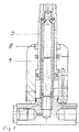
- This stripping combination is shown in FIG.
- the housing 1 is one Recessed 4, through which the housing is open upwards.
- the wiper combination 2 is used.
- This Scraper combination 2 consists of an insert 15, which with a Recess 5 is provided.
- This recess 5 is introduced so that the Insert 15 is open at the bottom.
- a U-shaped ring 6 pressed in metal.
- the U-shaped ring 6 has two legs of different lengths.
- the supporting leg 7 is so long that it with the Insert 15 is flush with the inside.
- the support leg 8 is used only for Support the U-shaped ring 6 down and can be short accordingly be kept.
- the U-shaped ring 6 is dimensioned so that its leg 7 the Split recess 5 approximately in the middle.
- a metal wiper is in this space of the recess 5 above the leg 7 9 introduced, which abuts the piston rod 3 and this Only approximately half the space in the recess.
- This metal wiper 9 is assigned an elastomer ring 10 through which the space in this part of the recess 5 is filled.
- the elastomer ring 10 is with provided two lips 11 which are chamfered at a predetermined angle.
- the same bevel is the inner wall of the insert 15 and the U-shaped Ring 6 assigned. So that the lips 11 are smooth and This prevents contaminated coolants from entering the interior of the Housing 1, as far as they migrate behind the metal wiper.
- this elastomer ring 10 still fulfills the task as an elastic member to center it between the metal wipers 9 and the wall and laterally absorb forces acting on the piston rod 3.
- Another elastomer ring 12 is embedded in the U-shaped ring 6.
- This elastomer ring 12 is provided with a lip 13 which is firmly attached to the Piston rod 3 hugs.
- This elastomer ring 12 takes over the task all liquids on the metal wiper 9 still on the piston rod to slide along. This creates a combination based on confined space and is also combined in one unit, which is easy to replace. This allows repairs to the wiper combination always carry out outside the housing.
- the insert 2 is in provide its outer upper part with a bevel 14. This slant causes some of the contaminated to act on the piston rod Coolant is derived.
- Such an insert 2 can be used wherever contaminated Liquids act directly on the work equipment. This is below this also applies to tools with slowly rotating shafts.
Landscapes
- Engineering & Computer Science (AREA)
- General Engineering & Computer Science (AREA)
- Mechanical Engineering (AREA)
- Processing And Handling Of Plastics And Other Materials For Molding In General (AREA)
- Hand Tools For Fitting Together And Separating, Or Other Hand Tools (AREA)
- Sealing Devices (AREA)
- Actuator (AREA)
- Food-Manufacturing Devices (AREA)
- Medicines Containing Material From Animals Or Micro-Organisms (AREA)
- Acyclic And Carbocyclic Compounds In Medicinal Compositions (AREA)
Abstract
Description
Die Lösung der Erfindung ist den kennzeichnenden Merkmalen der Ansprüche zu entnehmen.
- Fig. 1
- zeigt einen Querschnitt durch einen Schwenkspanner
- Fig. 2
- zeigt die Abstreifkombination
Claims (5)
- Abstreifvorrichtung für Arbeitsgeräte, die mit Kolbenstangen und oder langsam drehenden Wellen bestückt sind und die mit Metall- und Elastomer-Abstreifern versehen das Eindringen von verunreinigten Flüssigkeiten in das Innere der Arbeitsgeräte vermindern, dadurch gekennzeichnet, dass in dem Gehäuse (1) eines Arbeitsgerätes eine Ausnehmung (4) eingelassen ist, in die als Abstreif-Kombination (2) ein Einsatz (15) eingefügt ist, der eine Aussparung (5) besitzt, in die ein U-förmiger Ring (6) eingepresst ist, dessen einer Schenkel (7) bündig mit dem Innendurchmesser des Einsatzes (15) abschließt und den Raum innerhalb der Aussparung (5) in zwei Hälften teilt, dass oberhalb des Schenkel (7) ein Metall-Abstreifer (9) und unterhalb in den U-förmigen Ring (6) ein Elastomer-Ring (12) eingefügt sind.
- Abstreifvorrichtung nach Anspruch 1, dadurch gekennzeichnet, dass der Metall-Abstreifer (9) in seinem Außendurchmesser kleiner gehalten ist als der Innendurchmesser der Aussparung (5) und dass der Metall-Abstreifer (9) von einem Elastomer-Ring (10) umgeben ist, der zwei Lippen (11) besitzt, die der Innenwand der Aussparung zugeordneten Schrägen angepasst sind und dass der Elastomer-Ring (10) als elastisches Glied und Abstreifer zwischen Metall-Abstreifer (9) und Innenwand der Aussparung (5) wirkt.
- Abstreifvorrichtung nach Anspruch 1 u. 2, dadurch gekennzeichnet, dass in den U-förmigen Ring (6) ein Elastomer-Ring (12) eingefügt ist, der mit einer Lippe (13) versehen als Abstreifer wirkt.
- Abstreifvorrichtung nach Anspruch 1-3, dadurch gekennzeichnet, dass der Einsatz (15) im oberen Teil mit einer Schräge (14) versehen ist, die von Innen nach Außen abfällt.
- Abstreifvorrichtung nach Anspruch 1-4, dadurch gekennzeichnet, dass der Einsatz (15) mit seinem U-förmigen Ring (6), dem Metall-Abstreifer (9) und den Elastomer-Ringen (11;12) eine Einheit bildet, die auswechselbar ist.
Applications Claiming Priority (2)
| Application Number | Priority Date | Filing Date | Title |
|---|---|---|---|
| DE10045393A DE10045393A1 (de) | 2000-09-14 | 2000-09-14 | Abstreifkombination |
| DE10045393 | 2000-09-14 |
Publications (3)
| Publication Number | Publication Date |
|---|---|
| EP1188971A2 true EP1188971A2 (de) | 2002-03-20 |
| EP1188971A3 EP1188971A3 (de) | 2003-08-20 |
| EP1188971B1 EP1188971B1 (de) | 2005-03-23 |
Family
ID=7656133
Family Applications (1)
| Application Number | Title | Priority Date | Filing Date |
|---|---|---|---|
| EP01121126A Expired - Lifetime EP1188971B1 (de) | 2000-09-14 | 2001-09-04 | Abstreifkombination |
Country Status (3)
| Country | Link |
|---|---|
| EP (1) | EP1188971B1 (de) |
| AT (1) | ATE291707T1 (de) |
| DE (2) | DE10045393A1 (de) |
Cited By (3)
| Publication number | Priority date | Publication date | Assignee | Title |
|---|---|---|---|---|
| FR2853385A1 (fr) * | 2003-04-02 | 2004-10-08 | Bosch Gmbh Robert | Agencement d'etancheite et de guidage |
| WO2008071491A1 (de) * | 2006-12-15 | 2008-06-19 | Robert Bosch Gmbh | Abdichtvorrichtung für eine antriebswelle eines wischerantriebs, system zum aufbau entsprechender abdichtvorrichtungen und entsprechender wischerantrieb |
| EP3457006A4 (de) * | 2016-05-10 | 2019-05-15 | Nok Corporation | Staubdichtung |
Families Citing this family (1)
| Publication number | Priority date | Publication date | Assignee | Title |
|---|---|---|---|---|
| DE102009054721B4 (de) * | 2009-12-16 | 2017-07-06 | Robert Bosch Gmbh | Welle in einem Wellenlager, insbesondere Antriebswelle für eine Scheibenwischvorrichtung |
Family Cites Families (5)
| Publication number | Priority date | Publication date | Assignee | Title |
|---|---|---|---|---|
| US2264148A (en) * | 1940-06-06 | 1941-11-25 | Garlock Packing Co | Machinery packing |
| US3608911A (en) * | 1970-03-04 | 1971-09-28 | Ramsey Corp | Resilient plastic piston ring |
| DE3100627C2 (de) * | 1981-01-12 | 1983-07-07 | Festo-Maschinenfabrik Gottlieb Stoll, 7300 Esslingen | Einrichtung zum Lagern und Abdichten einer Kolbenstange in einem Zylinderdeckelbei pneumatsichen oder hydraulischen Arbeitszylindern |
| DE4441474A1 (de) * | 1994-11-22 | 1996-05-23 | Kaco Gmbh Co | Dichtungsvorrichtung |
| US5697710A (en) * | 1995-10-20 | 1997-12-16 | Nok Corporation | Bearing seals and bearing and seal assemblies |
-
2000
- 2000-09-14 DE DE10045393A patent/DE10045393A1/de not_active Withdrawn
-
2001
- 2001-09-04 DE DE50105673T patent/DE50105673D1/de not_active Expired - Fee Related
- 2001-09-04 AT AT01121126T patent/ATE291707T1/de not_active IP Right Cessation
- 2001-09-04 EP EP01121126A patent/EP1188971B1/de not_active Expired - Lifetime
Cited By (3)
| Publication number | Priority date | Publication date | Assignee | Title |
|---|---|---|---|---|
| FR2853385A1 (fr) * | 2003-04-02 | 2004-10-08 | Bosch Gmbh Robert | Agencement d'etancheite et de guidage |
| WO2008071491A1 (de) * | 2006-12-15 | 2008-06-19 | Robert Bosch Gmbh | Abdichtvorrichtung für eine antriebswelle eines wischerantriebs, system zum aufbau entsprechender abdichtvorrichtungen und entsprechender wischerantrieb |
| EP3457006A4 (de) * | 2016-05-10 | 2019-05-15 | Nok Corporation | Staubdichtung |
Also Published As
| Publication number | Publication date |
|---|---|
| EP1188971B1 (de) | 2005-03-23 |
| EP1188971A3 (de) | 2003-08-20 |
| DE50105673D1 (de) | 2005-04-28 |
| ATE291707T1 (de) | 2005-04-15 |
| DE10045393A1 (de) | 2002-03-28 |
Similar Documents
| Publication | Publication Date | Title |
|---|---|---|
| EP2835197A1 (de) | Spannfutter | |
| EP0790106A1 (de) | Greifvorrichtung bzw. Spannvorrichtung | |
| DE7902063U1 (de) | Vorrichtung zum aufspannen von werkzeugen, werkstuecken u.dgl. auf eine drehbare spindel | |
| DE2317779A1 (de) | Handbohrmaschine | |
| EP1188971A2 (de) | Abstreifkombination | |
| EP1190815B1 (de) | Verfahren und Vorrichtung zur dynamischen Schmierung eines Kraftspannfutters | |
| DE102004053083A1 (de) | Abstreif- und/oder Dichtungselement sowie Verfahren zum Abdichten eines Kolbens und Spann-und/oder Stützelement | |
| DE102014102071A1 (de) | Werkzeugmaschine mit Spanabstreifer | |
| DE102022127727A1 (de) | Mischwelle | |
| DE3148377A1 (de) | Kolbenstange mit kolben | |
| DE3340102C1 (de) | Vorrichtung zur Befestigung einer Werkzeugaufnahmehuelse auf einem Muldenschlitten einer Werkzeugmaschine | |
| DE2629365C3 (de) | Stichlochstopfmaschine für Schachtöfen, insbesondere Hochöfen | |
| DE102004043167B4 (de) | Laserschneidanlage | |
| DE102007034630B4 (de) | Spindelschutzvorrichtung für eine Spannvorrichtung sowie Spannvorrichtung | |
| DE972541C (de) | Verbindung geteilter Gehaeuse fuer elektrische Geraete, insbesondere Kabelgarnituren | |
| DE10225641A1 (de) | Druckstück sowie Spannelement mit einem solchen Druckstück | |
| EP0943395A2 (de) | Bohrgerät mit Absaugvorrichtung | |
| DE2245627A1 (de) | Arbeitszylinder, insbesondere fuer elektrochemische bearbeitungsmaschinen | |
| EP1655525B1 (de) | Abstreif- und/oder Dichtungselement sowie Verfahren zum Abdichten eines Kolbens und Spann- und/oder Stützelement | |
| DE3018204C2 (de) | ||
| DE2359316A1 (de) | Hydraulischer antrieb | |
| DE69926228T2 (de) | Dichtungsvorrichtung | |
| DE10242757A1 (de) | Pneumatisches Spannzeug | |
| DE706411C (de) | Stampfgeraet fuer den Strassenbau, fuer Giessereien o. dgl. | |
| DE2357825A1 (de) | Nutenverschluss fuer werkzeugmaschinentische |
Legal Events
| Date | Code | Title | Description |
|---|---|---|---|
| PUAI | Public reference made under article 153(3) epc to a published international application that has entered the european phase |
Free format text: ORIGINAL CODE: 0009012 |
|
| AK | Designated contracting states |
Kind code of ref document: A2 Designated state(s): AT BE CH CY DE DK ES FI FR GB GR IE IT LI LU MC NL PT SE TR |
|
| AX | Request for extension of the european patent |
Free format text: AL;LT;LV;MK;RO;SI |
|
| PUAL | Search report despatched |
Free format text: ORIGINAL CODE: 0009013 |
|
| AK | Designated contracting states |
Designated state(s): AT BE CH CY DE DK ES FI FR GB GR IE IT LI LU MC NL PT SE TR |
|
| AX | Request for extension of the european patent |
Extension state: AL LT LV MK RO SI |
|
| RAP1 | Party data changed (applicant data changed or rights of an application transferred) |
Owner name: LUDWIG EHRHARDT GMBH |
|
| 17P | Request for examination filed |
Effective date: 20040220 |
|
| 17Q | First examination report despatched |
Effective date: 20040330 |
|
| AKX | Designation fees paid |
Designated state(s): AT BE CH CY DE DK ES FI FR GB GR IE IT LI LU MC NL PT SE TR |
|
| GRAP | Despatch of communication of intention to grant a patent |
Free format text: ORIGINAL CODE: EPIDOSNIGR1 |
|
| GRAS | Grant fee paid |
Free format text: ORIGINAL CODE: EPIDOSNIGR3 |
|
| GRAA | (expected) grant |
Free format text: ORIGINAL CODE: 0009210 |
|
| AK | Designated contracting states |
Kind code of ref document: B1 Designated state(s): AT BE CH CY DE DK ES FI FR GB GR IE IT LI LU MC NL PT SE TR |
|
| PG25 | Lapsed in a contracting state [announced via postgrant information from national office to epo] |
Ref country code: TR Free format text: LAPSE BECAUSE OF FAILURE TO SUBMIT A TRANSLATION OF THE DESCRIPTION OR TO PAY THE FEE WITHIN THE PRESCRIBED TIME-LIMIT Effective date: 20050323 Ref country code: NL Free format text: LAPSE BECAUSE OF FAILURE TO SUBMIT A TRANSLATION OF THE DESCRIPTION OR TO PAY THE FEE WITHIN THE PRESCRIBED TIME-LIMIT Effective date: 20050323 Ref country code: IE Free format text: LAPSE BECAUSE OF FAILURE TO SUBMIT A TRANSLATION OF THE DESCRIPTION OR TO PAY THE FEE WITHIN THE PRESCRIBED TIME-LIMIT Effective date: 20050323 Ref country code: FI Free format text: LAPSE BECAUSE OF FAILURE TO SUBMIT A TRANSLATION OF THE DESCRIPTION OR TO PAY THE FEE WITHIN THE PRESCRIBED TIME-LIMIT Effective date: 20050323 |
|
| REG | Reference to a national code |
Ref country code: GB Ref legal event code: FG4D Free format text: NOT ENGLISH |
|
| REG | Reference to a national code |
Ref country code: CH Ref legal event code: EP |
|
| REG | Reference to a national code |
Ref country code: IE Ref legal event code: FG4D Free format text: GERMAN |
|
| REF | Corresponds to: |
Ref document number: 50105673 Country of ref document: DE Date of ref document: 20050428 Kind code of ref document: P |
|
| PG25 | Lapsed in a contracting state [announced via postgrant information from national office to epo] |
Ref country code: GR Free format text: LAPSE BECAUSE OF FAILURE TO SUBMIT A TRANSLATION OF THE DESCRIPTION OR TO PAY THE FEE WITHIN THE PRESCRIBED TIME-LIMIT Effective date: 20050623 Ref country code: DK Free format text: LAPSE BECAUSE OF FAILURE TO SUBMIT A TRANSLATION OF THE DESCRIPTION OR TO PAY THE FEE WITHIN THE PRESCRIBED TIME-LIMIT Effective date: 20050623 |
|
| PG25 | Lapsed in a contracting state [announced via postgrant information from national office to epo] |
Ref country code: ES Free format text: LAPSE BECAUSE OF FAILURE TO SUBMIT A TRANSLATION OF THE DESCRIPTION OR TO PAY THE FEE WITHIN THE PRESCRIBED TIME-LIMIT Effective date: 20050704 |
|
| GBT | Gb: translation of ep patent filed (gb section 77(6)(a)/1977) |
Effective date: 20050719 |
|
| NLV1 | Nl: lapsed or annulled due to failure to fulfill the requirements of art. 29p and 29m of the patents act | ||
| PG25 | Lapsed in a contracting state [announced via postgrant information from national office to epo] |
Ref country code: CY Free format text: LAPSE BECAUSE OF FAILURE TO SUBMIT A TRANSLATION OF THE DESCRIPTION OR TO PAY THE FEE WITHIN THE PRESCRIBED TIME-LIMIT Effective date: 20050904 |
|
| PG25 | Lapsed in a contracting state [announced via postgrant information from national office to epo] |
Ref country code: PT Free format text: LAPSE BECAUSE OF FAILURE TO SUBMIT A TRANSLATION OF THE DESCRIPTION OR TO PAY THE FEE WITHIN THE PRESCRIBED TIME-LIMIT Effective date: 20050907 |
|
| PG25 | Lapsed in a contracting state [announced via postgrant information from national office to epo] |
Ref country code: MC Free format text: LAPSE BECAUSE OF NON-PAYMENT OF DUE FEES Effective date: 20050930 Ref country code: BE Free format text: LAPSE BECAUSE OF NON-PAYMENT OF DUE FEES Effective date: 20050930 Ref country code: LU Free format text: LAPSE BECAUSE OF NON-PAYMENT OF DUE FEES Effective date: 20050930 |
|
| REG | Reference to a national code |
Ref country code: IE Ref legal event code: FD4D |
|
| PLBE | No opposition filed within time limit |
Free format text: ORIGINAL CODE: 0009261 |
|
| STAA | Information on the status of an ep patent application or granted ep patent |
Free format text: STATUS: NO OPPOSITION FILED WITHIN TIME LIMIT |
|
| ET | Fr: translation filed | ||
| 26N | No opposition filed |
Effective date: 20051227 |
|
| BERE | Be: lapsed |
Owner name: LUDWIG EHRHARDT G.M.B.H. Effective date: 20050930 |
|
| PG25 | Lapsed in a contracting state [announced via postgrant information from national office to epo] |
Ref country code: SE Free format text: LAPSE BECAUSE OF FAILURE TO SUBMIT A TRANSLATION OF THE DESCRIPTION OR TO PAY THE FEE WITHIN THE PRESCRIBED TIME-LIMIT Effective date: 20050623 |
|
| PGFP | Annual fee paid to national office [announced via postgrant information from national office to epo] |
Ref country code: CH Payment date: 20080923 Year of fee payment: 8 |
|
| PGFP | Annual fee paid to national office [announced via postgrant information from national office to epo] |
Ref country code: AT Payment date: 20080919 Year of fee payment: 8 Ref country code: FR Payment date: 20080917 Year of fee payment: 8 Ref country code: IT Payment date: 20080925 Year of fee payment: 8 |
|
| PGFP | Annual fee paid to national office [announced via postgrant information from national office to epo] |
Ref country code: GB Payment date: 20080922 Year of fee payment: 8 |
|
| PGFP | Annual fee paid to national office [announced via postgrant information from national office to epo] |
Ref country code: DE Payment date: 20080930 Year of fee payment: 8 |
|
| REG | Reference to a national code |
Ref country code: CH Ref legal event code: PL |
|
| GBPC | Gb: european patent ceased through non-payment of renewal fee |
Effective date: 20090904 |
|
| REG | Reference to a national code |
Ref country code: FR Ref legal event code: ST Effective date: 20100531 |
|
| PG25 | Lapsed in a contracting state [announced via postgrant information from national office to epo] |
Ref country code: AT Free format text: LAPSE BECAUSE OF NON-PAYMENT OF DUE FEES Effective date: 20090904 |
|
| PG25 | Lapsed in a contracting state [announced via postgrant information from national office to epo] |
Ref country code: FR Free format text: LAPSE BECAUSE OF NON-PAYMENT OF DUE FEES Effective date: 20090930 Ref country code: DE Free format text: LAPSE BECAUSE OF NON-PAYMENT OF DUE FEES Effective date: 20100401 |
|
| PG25 | Lapsed in a contracting state [announced via postgrant information from national office to epo] |
Ref country code: LI Free format text: LAPSE BECAUSE OF NON-PAYMENT OF DUE FEES Effective date: 20090930 Ref country code: CH Free format text: LAPSE BECAUSE OF NON-PAYMENT OF DUE FEES Effective date: 20090930 |
|
| PG25 | Lapsed in a contracting state [announced via postgrant information from national office to epo] |
Ref country code: GB Free format text: LAPSE BECAUSE OF NON-PAYMENT OF DUE FEES Effective date: 20090904 |
|
| PG25 | Lapsed in a contracting state [announced via postgrant information from national office to epo] |
Ref country code: IT Free format text: LAPSE BECAUSE OF NON-PAYMENT OF DUE FEES Effective date: 20090904 |