EP1188977A1 - Embout de tuyau souple - Google Patents
Embout de tuyau souple Download PDFInfo
- Publication number
- EP1188977A1 EP1188977A1 EP00120453A EP00120453A EP1188977A1 EP 1188977 A1 EP1188977 A1 EP 1188977A1 EP 00120453 A EP00120453 A EP 00120453A EP 00120453 A EP00120453 A EP 00120453A EP 1188977 A1 EP1188977 A1 EP 1188977A1
- Authority
- EP
- European Patent Office
- Prior art keywords
- hose
- connecting pipe
- pipe
- connection
- oval
- Prior art date
- Legal status (The legal status is an assumption and is not a legal conclusion. Google has not performed a legal analysis and makes no representation as to the accuracy of the status listed.)
- Withdrawn
Links
- 239000012530 fluid Substances 0.000 claims abstract description 13
- 238000005516 engineering process Methods 0.000 claims abstract description 7
- 239000000463 material Substances 0.000 description 2
- 238000007789 sealing Methods 0.000 description 2
- 230000008878 coupling Effects 0.000 description 1
- 238000010168 coupling process Methods 0.000 description 1
- 238000005859 coupling reaction Methods 0.000 description 1
- 230000001419 dependent effect Effects 0.000 description 1
- 238000011161 development Methods 0.000 description 1
- 230000018109 developmental process Effects 0.000 description 1
- 239000008187 granular material Substances 0.000 description 1
- 239000011343 solid material Substances 0.000 description 1
Images

Classifications
-
- F—MECHANICAL ENGINEERING; LIGHTING; HEATING; WEAPONS; BLASTING
- F16—ENGINEERING ELEMENTS AND UNITS; GENERAL MEASURES FOR PRODUCING AND MAINTAINING EFFECTIVE FUNCTIONING OF MACHINES OR INSTALLATIONS; THERMAL INSULATION IN GENERAL
- F16L—PIPES; JOINTS OR FITTINGS FOR PIPES; SUPPORTS FOR PIPES, CABLES OR PROTECTIVE TUBING; MEANS FOR THERMAL INSULATION IN GENERAL
- F16L33/00—Arrangements for connecting hoses to rigid members; Rigid hose-connectors, i.e. single members engaging both hoses
- F16L33/30—Arrangements for connecting hoses to rigid members; Rigid hose-connectors, i.e. single members engaging both hoses comprising parts inside the hoses only
Definitions
- the invention relates to a connecting pipe for a hose according to the Preamble of claim 1.
- Such connecting pipes are suitable in fluid technology for connecting a Hose to a device, for example to a fluidic drive or to a Pressure sensor or also for connecting hoses.
- a connecting pipe of this type is known (US 4,603,890), which has frustoconical steps through which an elastic hose is held.
- the connection between the hose and the connecting pipe can be sealed with a sealing ring and secured with a clamp or clamp become.
- the known connecting pipes have the disadvantage that the connection between a hose and the connecting pipe is difficult to solve when the hose should not be damaged when loosening, since the frustoconical steps prevent easy disconnection of the hose, which is actually their job equivalent. Furthermore, the geometry is within relatively narrow limits To match the inside diameter and the elasticity of the hoses to be connected, which is often difficult in practice when different products are connected to a certain device.
- the invention has for its object a connecting pipe for To propose hose connections that can be detached multiple times without much effort, without causing an inadmissible material wear.
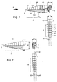
- Fig. 1, 1 means a connection pipe for a flexible, not shown Hose, which is used to create an easily detachable connection between the Hose and the connecting pipe 1 in the direction of an arrow R on the Connection pipe 1 is slidable.
- the connecting pipe 1 has one in a pipe axis 2 extending passage 3 for a fluid.
- the connecting pipe 1 are perpendicular to the tube axis
- Cross-sectional areas of the connecting pipe 1 are oval on the outside.
- the oval Cross-sectional areas therefore have a large outer diameter d2 and one small outer diameter d1.
- a certain area 4 of the connecting pipe 1, which is used to slip the Hose is provided, is advantageously at least one acting as a barb Level 5.1, 5.2, 5.3, 5.4, 5.5, 5.6 trained, which each advantageously take the form of a Have a truncated cone or a truncated paraboloid.
- the outer shape of the connecting pipe 1 in the region 4 is basically conical executed.
- An outer diameter d2 and / or d1 of the connecting pipe 1 takes So over the certain area 4, which is provided for slipping on the hose is, in the direction R, in which the hose when connecting via the Connection pipe 4 is slidable, essentially, provided that the possibly executed Levels 5.1, 5.2, 5.3, 5.4, 5.5, 5.6 are disregarded in this consideration.
- the connecting pipe 1 serves as a line section with a closed cross section, which is particularly suitable for conveying fluids. It goes without saying that with suitable dimensions of the passage 3 also solid materials, for example a granulate through which the connecting pipe 1 can be conveyed.
- the connecting pipe 1 is particularly versatile in fluid technology. Depending on intended use, one end 10 of the connecting pipe 1 is functional designed by, for example, a thread or a flange for attaching the Connection tube 1 is formed on a device. It goes without saying that that Connection tube 1 but also advantageously in one piece in a housing part or on a facility can be trained.
- a device 15 has two copies of the oval connecting pipe 1.
- the Device 15 is, for example, a sensor for measuring a pressure difference between two fluids, which can be supplied to the device 15 in flexible hoses 16 and 17.
- the two tubes 16 and 17 are preferably round and are on the oval Connection pipes 1 pushed on.
- two or more oval connecting pipes 1 are as Hose connecting elements can be joined, two versions of the Connection pipe 1 - as shown in Fig. 4 - as a quick coupling for two Hoses 18 and 19, three versions of the connecting pipe 1 as a T-shaped or Y-shaped Hose connection element or four versions of the connecting pipe 1 as a cross connector for four hoses can be joined to some To name examples.
- the oval cross-sectional areas of the Connecting pipe 1 initially cause a connection in area 4 round hose a deformation, which when rotating the hose around the Pipe axis 2 is at least partially plastic, so that the hose after a slight rotation around the tube axis 2 without problems against the drawn Have the direction of arrow R removed from the connecting pipe 1.
- the outer shape of said oval cross-sectional areas of the connecting pipe 1 can vary within relatively wide limits, the limits essentially differing from the Deformability and the inner diameter of the hose, the expected pressure of the Fluids and the required security depend. Good functionality for hoses with an inner diameter of about 4 mm and a pressure of up to 6 bar, if the oval cross-sectional areas are elliptical and the ratio of the small outer diameter d1 to the large outer diameter d2 is approximately 3: 4.
- connection between the hose and the connecting pipe 1 additionally sealed with a sealing ring and with a clamp or clamp secured.
- An embodiment of the oval connecting pipe 1 according to the invention is not necessarily constructed symmetrically to the passage channel 3.
- the passage channel 3 lies on an axis 12, which probably according to a first side view in Fig. 2 symmetrically between Straight lines e1 and e2 shown in dashed lines, which the area 4 over the envelop larger outer diameter d2.
- the axis 12 is not dashed symmetrically between others straight lines shown e3 and e4, which the area 4 over the smaller outer Wrap in diameter d1.
Landscapes
- Engineering & Computer Science (AREA)
- General Engineering & Computer Science (AREA)
- Mechanical Engineering (AREA)
- Joints That Cut Off Fluids, And Hose Joints (AREA)
- Quick-Acting Or Multi-Walled Pipe Joints (AREA)
Priority Applications (2)
| Application Number | Priority Date | Filing Date | Title |
|---|---|---|---|
| EP00120453A EP1188977A1 (fr) | 2000-09-19 | 2000-09-19 | Embout de tuyau souple |
| DE20017756U DE20017756U1 (de) | 2000-09-19 | 2000-10-17 | Anschlußrohr für einen Schlauch |
Applications Claiming Priority (1)
| Application Number | Priority Date | Filing Date | Title |
|---|---|---|---|
| EP00120453A EP1188977A1 (fr) | 2000-09-19 | 2000-09-19 | Embout de tuyau souple |
Publications (1)
| Publication Number | Publication Date |
|---|---|
| EP1188977A1 true EP1188977A1 (fr) | 2002-03-20 |
Family
ID=8169873
Family Applications (1)
| Application Number | Title | Priority Date | Filing Date |
|---|---|---|---|
| EP00120453A Withdrawn EP1188977A1 (fr) | 2000-09-19 | 2000-09-19 | Embout de tuyau souple |
Country Status (2)
| Country | Link |
|---|---|
| EP (1) | EP1188977A1 (fr) |
| DE (1) | DE20017756U1 (fr) |
Cited By (2)
| Publication number | Priority date | Publication date | Assignee | Title |
|---|---|---|---|---|
| CN103083799A (zh) * | 2011-11-03 | 2013-05-08 | 江苏康诺医疗器械有限公司 | 多径段双向接头 |
| DE102013021992A1 (de) | 2013-04-18 | 2014-10-23 | Eagle Actuator Components Gmbh & Co. Kg | Anordnung mit einem Anschlussstutzen und einer Leitung |
Citations (6)
| Publication number | Priority date | Publication date | Assignee | Title |
|---|---|---|---|---|
| US4597594A (en) * | 1983-09-09 | 1986-07-01 | Chris Kaye Plastics Corp. | Hose connector |
| US4603890A (en) | 1984-12-06 | 1986-08-05 | Robert Huppee | Barbed tubing connector |
| US4875719A (en) * | 1989-01-26 | 1989-10-24 | Mylett Christopher J | Universal hose connector |
| US5165733A (en) * | 1988-02-19 | 1992-11-24 | Sampson Richard K | Apparatus for connecting an elastic hose to a system |
| EP0886096A1 (fr) * | 1997-06-19 | 1998-12-23 | FESTO AG & Co | Dispositif de connexion et distributeur de fluide comportant un ou plusieurs de ces dispositifs de connexion |
| EP0959289A1 (fr) | 1998-04-22 | 1999-11-24 | M.G.I. Coutier S.A. | Dispositif de connexion pour le raccordement d'un tube sur un interface |
-
2000
- 2000-09-19 EP EP00120453A patent/EP1188977A1/fr not_active Withdrawn
- 2000-10-17 DE DE20017756U patent/DE20017756U1/de not_active Expired - Lifetime
Patent Citations (6)
| Publication number | Priority date | Publication date | Assignee | Title |
|---|---|---|---|---|
| US4597594A (en) * | 1983-09-09 | 1986-07-01 | Chris Kaye Plastics Corp. | Hose connector |
| US4603890A (en) | 1984-12-06 | 1986-08-05 | Robert Huppee | Barbed tubing connector |
| US5165733A (en) * | 1988-02-19 | 1992-11-24 | Sampson Richard K | Apparatus for connecting an elastic hose to a system |
| US4875719A (en) * | 1989-01-26 | 1989-10-24 | Mylett Christopher J | Universal hose connector |
| EP0886096A1 (fr) * | 1997-06-19 | 1998-12-23 | FESTO AG & Co | Dispositif de connexion et distributeur de fluide comportant un ou plusieurs de ces dispositifs de connexion |
| EP0959289A1 (fr) | 1998-04-22 | 1999-11-24 | M.G.I. Coutier S.A. | Dispositif de connexion pour le raccordement d'un tube sur un interface |
Cited By (2)
| Publication number | Priority date | Publication date | Assignee | Title |
|---|---|---|---|---|
| CN103083799A (zh) * | 2011-11-03 | 2013-05-08 | 江苏康诺医疗器械有限公司 | 多径段双向接头 |
| DE102013021992A1 (de) | 2013-04-18 | 2014-10-23 | Eagle Actuator Components Gmbh & Co. Kg | Anordnung mit einem Anschlussstutzen und einer Leitung |
Also Published As
| Publication number | Publication date |
|---|---|
| DE20017756U1 (de) | 2002-02-14 |
Similar Documents
| Publication | Publication Date | Title |
|---|---|---|
| EP3173675B1 (fr) | Raccord de tuyau | |
| DE19650601A1 (de) | Anschlußkörper für druckmittelleitende Steckverbindungen | |
| DE102005027816A1 (de) | Rohrverbindung | |
| EP0170845A1 (fr) | Foret de perforation pour jonction d'un branchement sur un tuyau | |
| DE3237929A1 (de) | Rohr- oder schlauchverbindung | |
| EP0003746B1 (fr) | Raccordement à fiche | |
| DE10126429B4 (de) | Schlaucheinrichtung zum Transportieren von Fluiden | |
| DE10357892A1 (de) | Vorrichtung zum Verbinden mit einem Ende eines Wellrohres | |
| EP0577803B1 (fr) | Tubulure de raccordement | |
| WO2017190822A1 (fr) | Dispositif de liaison, en particulier sous la forme d'un raccord de tuyaux | |
| CH665465A5 (de) | Rohrverbindung fuer kunststoffrohre. | |
| DE69901563T2 (de) | Anordnungsverfahren zum verbinden einer armatur mit einem rohrelement und ein neuer typ kupplung zur duerchführung des verfahrens | |
| EP1188977A1 (fr) | Embout de tuyau souple | |
| EP2199652B1 (fr) | Dispositif de connexion étanche et de fixation d'une conduite de fluide dotée d'un autre composant conduisant du liquide | |
| EP3322923B1 (fr) | Raccord de conduite sanitaire | |
| DE19504698C1 (de) | Anbohrarmatur | |
| EP2843283B1 (fr) | Système de convoyeur par succion | |
| EP1118811A2 (fr) | Conduite flexible avec un dispositif de raccordement sur au moins une extrémité | |
| EP3963245A1 (fr) | Couplage de raccordement | |
| DE4318831C2 (de) | Kupplungsvorrichtung für Rohre | |
| DE4211959A1 (de) | Rohrverbindung | |
| DE102006027438B4 (de) | Saugschlauch für Staubsauger | |
| DE1536900C3 (de) | Lösbare Befestigungseinrichtung für Filterkörper | |
| DE19816231C1 (de) | Anschlußnippel | |
| DE29509132U1 (de) | Lösbare Hochdruck-Schlauch-Verbindung |
Legal Events
| Date | Code | Title | Description |
|---|---|---|---|
| PUAI | Public reference made under article 153(3) epc to a published international application that has entered the european phase |
Free format text: ORIGINAL CODE: 0009012 |
|
| AK | Designated contracting states |
Kind code of ref document: A1 Designated state(s): AT BE CH CY DE DK ES FI FR GB GR IE IT LI LU MC NL PT SE |
|
| AX | Request for extension of the european patent |
Free format text: AL;LT;LV;MK;RO;SI |
|
| AKX | Designation fees paid | ||
| REG | Reference to a national code |
Ref country code: DE Ref legal event code: 8566 |
|
| STAA | Information on the status of an ep patent application or granted ep patent |
Free format text: STATUS: THE APPLICATION IS DEEMED TO BE WITHDRAWN |
|
| 18D | Application deemed to be withdrawn |
Effective date: 20020921 |