EP1188978A2 - Steckmuffe zum Verbinden von Rohren aus Kunststoff - Google Patents
Steckmuffe zum Verbinden von Rohren aus Kunststoff Download PDFInfo
- Publication number
- EP1188978A2 EP1188978A2 EP01810900A EP01810900A EP1188978A2 EP 1188978 A2 EP1188978 A2 EP 1188978A2 EP 01810900 A EP01810900 A EP 01810900A EP 01810900 A EP01810900 A EP 01810900A EP 1188978 A2 EP1188978 A2 EP 1188978A2
- Authority
- EP
- European Patent Office
- Prior art keywords
- tabs
- push
- sleeve
- sleeve according
- pipe end
- Prior art date
- Legal status (The legal status is an assumption and is not a legal conclusion. Google has not performed a legal analysis and makes no representation as to the accuracy of the status listed.)
- Granted
Links
Images
Classifications
-
- F—MECHANICAL ENGINEERING; LIGHTING; HEATING; WEAPONS; BLASTING
- F16—ENGINEERING ELEMENTS AND UNITS; GENERAL MEASURES FOR PRODUCING AND MAINTAINING EFFECTIVE FUNCTIONING OF MACHINES OR INSTALLATIONS; THERMAL INSULATION IN GENERAL
- F16L—PIPES; JOINTS OR FITTINGS FOR PIPES; SUPPORTS FOR PIPES, CABLES OR PROTECTIVE TUBING; MEANS FOR THERMAL INSULATION IN GENERAL
- F16L37/00—Couplings of the quick-acting type
- F16L37/08—Couplings of the quick-acting type in which the connection between abutting or axially overlapping ends is maintained by locking members
- F16L37/084—Couplings of the quick-acting type in which the connection between abutting or axially overlapping ends is maintained by locking members combined with automatic locking
- F16L37/091—Couplings of the quick-acting type in which the connection between abutting or axially overlapping ends is maintained by locking members combined with automatic locking by means of a ring provided with teeth or fingers
Definitions
- the invention relates to a push-in sleeve for connecting pipes made of plastic with at least one ring groove on the inside has, in which a sealant made of rubber-elastic Material is arranged and with a likewise on this inside arranged claw ring around the inserted into the sleeve To prevent pipe end from escaping, the claw ring a plurality has inwardly directed, elastically deformable tabs, which are determined when pulling the pipe end out claw the sleeve into the surface of the pipe.
- a plug-in sleeve of this type is in the prior art from CH 590 423 A5 of the applicant.
- This has one Claw ring with rags bent inwards at an angle.
- the tabs When inserting At one end of the tube, the tabs are bent slightly outwards.
- the front edges of the rags cut when pulled back of the pipe end into the surface of the pipe end and prevent it thereby pulling out the pipe end.
- By inserting one the sheet metal coupling can be separated again become.
- this push-in sleeve has itself proven many times. With comparatively large pipe diameters of 10 cm, for example, there is the difficulty that the pipe end is pushed into the push-in socket with great force must become. Since the pipe ends are usually pushed in by hand the required joining forces are disadvantageous and complicate assembly. There is also a risk that the pipe is tilted during insertion.
- the invention has for its object a plug-in sleeve mentioned type to create that with much lower forces is available and yet the required high pull-out force has.
- the task is with a generic push-in sleeve solved that the lobes are incisor-shaped and flexible are formed and that they are essentially in a transverse to Axial direction of the push-in sleeve extending plane are arranged.
- the tabs are incisor-shaped and much more flexible than before.
- the incisor-shaped formation has the consequence that the rags are mainly bent at the bottom.
- the flaps can be comparatively flat on the pipe end be created, which is an effective anchorage when retracting of the pipe results.
- each one Have tooth base with a tooth neck that is essential is narrower than a tooth cutting edge.
- the lobes are preferred trained so that they continuously from the tooth cutting edge taper to the tooth base. This results in the assembled state a very advantageous bending curve, which is an effective anchor guaranteed.
- the anchorage is then particularly effective if the lobes have a tooth cutting edge that is concave is such that they are assembled with the above Surface of the tube two spaced apart Forms contact surfaces. When pulling back the pipe end dig the two contact surfaces into the pipe.
- the two Contact areas can be made narrow in some areas and thus it is guaranteed that the rags even at comparative little tension dig into the surface.
- the claw ring is particularly effective when it is essential has more lobes than before, preferably it has more than thirty in particular more than fifty comparatively narrow Rag on. Center them when inserting a pipe end numerous rags effectively end the pipe and prevent tilting.
- a particularly simple construction of the push-in sleeve is then obtained if according to a development of the invention the claw ring with the sealing ring is inserted in the same groove.
- the claw ring is then preferably between a groove wall and the sealing ring clamped.
- the claw ring is flat and flat, it can be particularly inexpensive as Stamped part or manufactured as a laser / water jet cutting part become.
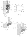
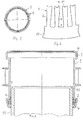
- the 7 has a substantially cylindrical and hollow sleeve body 3 with two spaced apart arranged annular grooves 4 and 16, at least in one of these grooves is a rubber-elastic sealing ring 2 or another suitable sealant is used.
- a rubber-elastic sealing ring 2 or another suitable sealant is used in the groove 4 in the groove 4 .
- a claw ring 5 used, as can be seen is clamped by the sealing ring 2 against a groove wall.
- the other groove 16 can also be a sealing ring and one Have a claw ring, but this is not mandatory.
- the claw ring 5 consists of resilient material, in particular resilient steel and is preferably a flat one Stamping. According to FIGS. 5 and 6, it has a plurality of Flaps that are directed radially inwards and are incisor-shaped are trained. The number of these lobes is 6 comparatively large and the distances between the tabs 6 correspond approximately to the width of these tabs 6. The tabs 6 are thus comparatively close and preferably more than thirty and in particular more than fifty rags 6 intended.
- the tabs 6 each have a tooth cutting edge at the free front end 7 and a tooth neck 8, which continuously opposes a tooth base 9 tapers, as in particular FIG. 2 clearly shows.
- the tooth cutting edge 7 forms a concave front edge 11, such that corners 10 are particularly exposed on the front are.
- the tabs are in the unloaded state and thus before coupling 6 aligned radially inwards according to FIG. 3 and lie in a plane transverse to the direction of insertion. Preferably all tabs 6 are in this plane, but this is not mandatory.
- the insertion direction is in FIG. 4 with the arrow 16 indicated.
- FIG. 4 If a pipe end 12 is installed, this is shown in FIG. 4 in In the direction of arrow 16 inserted into the sleeve 1.
- the pipe end according to FIG. 3, 12 first comes in with the sealing ring 2 Intervention.
- the sealing ring 2 detects several internally directed ribs 2a on which the pipe end 12 centers becomes.
- the pipe end 12 is based on the position according to Fig. 3 pushed further inwards, the front side arrives 13 of the tube end engages with the tab 6 and bends this finally in the position shown in Fig. 4.
- tabs 6 are bent above all at the tooth base 9.
- the tabs 6 each have one Bending edge 17, which is close to the body 3 of the sleeve 1.
- the flaps 6 are comparatively at an angle ⁇ flat on the outside 18 of the pipe end 12. That angle 18 is preferably in the range of 15 ° to 25 °. Rag 6 are, as can be seen, comparatively narrow and flexible educated. You can therefore use comparatively little force be bent. Because of the narrow and soft elastic Training is the resistance of the tab 6 when inserting the Pipe end 12 comparatively even with very numerous tabs 6 small. Since the flap 6 by a comparatively large angle ⁇ are bent, the contact pressure on the surface 18 is nevertheless comparatively high.
- the rags 6 each dig with their Cutting edge 7 into the surface 18.
- the cutting edges set 7 each with their corners 10 and these dig themselves thus first into the surface 18.
- the tabs 6 thus have two comparatively short and spaced apart Contact surfaces.
Landscapes
- Engineering & Computer Science (AREA)
- General Engineering & Computer Science (AREA)
- Mechanical Engineering (AREA)
- Quick-Acting Or Multi-Walled Pipe Joints (AREA)
- Branch Pipes, Bends, And The Like (AREA)
Abstract
Description
- Fig. 1
- ein Achsialschnitt durch einen Abschnitt der erfindungsgemässen Steckmuffe sowie ein Abschnitt eines eingesetzten Rohrendes,
- Fig. 2
- eine Ansicht eines Lappens eines Krallringes,
- Fig. 3 und 4
- schematisch das Umbiegen der Lappen beim Einschieben eines Rohrendes,
- Fig. 5
- eine Ansicht eines Krallringes im unbelasteten Zustand,
- Fig. 6
- ein stark vergrösserter Abschnitt des Krallringes gemäss Fig. 5 und
- Fig. 7
- ein Achsialschnitt durch die erfindungsgemässe Muffe mit einem Abschnitt eines eingeführten Rohrendes.
Claims (14)
- Steckmuffe zum Verbinden von Rohren aus Kunststoff, die an ihrer Innenseite mindestens eine Ringnut (4) aufweist, in welcher ein Dichtungsmittel (2) aus gummielastischem Material angeordnet ist und mit einem ebenfalls an dieser Innenseite angeordneten Krallring (5), um das in die Muffe (1) eingeführte Rohrende (12) am Austreten zu hindern, wobei der Krallring (5) eine Mehrzahl nach einwärts gerichtete, elastisch verformbare Lappen (6) aufweist, die bestimmt sind, beim Herausziehen des Rohrendes (12) aus der Muffe (1) in die Oberfläche (18) des Rohrendes (12) einzukrallen, dadurch gekennzeichnet, dass die Lappen (6) schneidezahnförmig und biegeelastisch ausgebildet sind und dass sie im wesentlichen in einer quer zur Achsrichtung verlaufenden Ebene angeordnet sind.
- Steckmuffe nach Anspruch 1, dadurch gekennzeichnet, dass die Lappen (6) jeweils einen Zahngrund (9) mit einem Zahnhals (8) aufweisen, der wesentlich schmaler ist als eine Zahnschneide (7).
- Steckmuffe nach Anspruch 1 oder 2, dadurch gekennzeichnet, dass die Lappen (6) jeweils eine Zahnschneide (7) aufweisen, die konkav ausgebildet ist, derart, dass sie im montierten Zustand mit der genannten Oberfläche (18) des Rohrendes (12) zwei im Abstand zueinander angeordnete Kontaktflächen (10) bildet.
- Steckmuffe nach einem der Ansprüche 1 bis 3, dadurch gekennzeichnet, dass die Lappen (6) im montierten Zustand vorwiegend jeweils an ihrer Ansatzstelle (17)gebogen sind.
- Steckmuffe nach einem der Ansprüche 1 bis 4, dadurch gekennzeichnet, dass die Lappen (6) jeweils einen V-förmigen Zahnhals (8) aufweisen, der im montierten Zustand eine Biegekante (17) bildet.
- Steckmuffe nach einem der Ansprüche 1 bis 5, dadurch gekennzeichnet, dass die Länge der Lappen (6) so gewählt ist, dass sie im montierten Zustand mit einem Winkel (α) im Bereich von 15° bis 25° an der genannten Oberfläche (18) des Rohrendes (12) anliegen.
- Steckmuffe nach einem der Ansprüche 1 bis 6, dadurch gekennzeichnet, dass beim unbelasteten Krallring (5) die Lappen (6) mit einem ringförmigen äusseren Körper (14) in einer Ebene angeordnet sind.
- Steckmuffe nach einem der Ansprüche 1 bis 7, dadurch gekennzeichnet, dass beim Einschieben eines Rohrendes (12) die Lappen (6) um einen Winkel (β) grösser als 45° umgebogen werden.
- Steckmuffe nach einem der Ansprüche 1 bis 8, dadurch gekennzeichnet, dass der Krallring (5) ein Stanz-, Laser- oder Wasserstrahlschneidteil ist.
- Steckmuffe nach einem der Ansprüche 1 bis 9, dadurch gekennzeichnet, dass der Krallring (5) mit einem Dichtungsring (2) in dieselbe Nut eingesetzt ist.
- Steckmuffe nach Anspruch 10, dadurch gekennzeichnet, dass der Krallring (5) zwischen dem Dichtungsring (2) und einer Nutenwand (4) angeordnet ist.
- Krallring für eine Steckmuffe nach einem der Ansprüche 1 bis 11, dadurch gekennzeichnet, dass er ein ebenes Stanzteil ist.
- Krallring nach Anspruch 12, dadurch gekennzeichnet, dass die Lappen (6) nicht wesentlich breiter sind als die Abstände zwischen zwei benachbarten Lappen(6).
- Krallring gemäss Anspruch 12 oder 13, dadurch gekennzeichnet, dass er mehr als 30 vorzugsweise mehr als 50 Lappen (6) aufweist.
Applications Claiming Priority (2)
| Application Number | Priority Date | Filing Date | Title |
|---|---|---|---|
| CH18042000 | 2000-09-18 | ||
| CH18042000 | 2000-09-18 |
Publications (3)
| Publication Number | Publication Date |
|---|---|
| EP1188978A2 true EP1188978A2 (de) | 2002-03-20 |
| EP1188978A3 EP1188978A3 (de) | 2003-11-26 |
| EP1188978B1 EP1188978B1 (de) | 2005-10-05 |
Family
ID=4566345
Family Applications (1)
| Application Number | Title | Priority Date | Filing Date |
|---|---|---|---|
| EP01810900A Expired - Lifetime EP1188978B1 (de) | 2000-09-18 | 2001-09-18 | Steckmuffe zum Verbinden von Rohren aus Kunststoff |
Country Status (3)
| Country | Link |
|---|---|
| EP (1) | EP1188978B1 (de) |
| AT (1) | ATE306041T1 (de) |
| DE (1) | DE50107602D1 (de) |
Cited By (1)
| Publication number | Priority date | Publication date | Assignee | Title |
|---|---|---|---|---|
| EP1882875A1 (de) | 2006-07-27 | 2008-01-30 | Geberit Technik Ag | Steckmuffe zum Verbinden von Rohren |
Families Citing this family (1)
| Publication number | Priority date | Publication date | Assignee | Title |
|---|---|---|---|---|
| DE102013018439A1 (de) | 2013-11-05 | 2015-05-07 | Cta Anlagenbau Gmbh | Vorrichtung zum Montieren einer Stütz- und Dehnmuffe für Rohrleitungen |
Citations (1)
| Publication number | Priority date | Publication date | Assignee | Title |
|---|---|---|---|---|
| CH590423A5 (de) | 1975-04-24 | 1977-08-15 | Geberit Ag |
Family Cites Families (4)
| Publication number | Priority date | Publication date | Assignee | Title |
|---|---|---|---|---|
| US4123090A (en) * | 1976-07-19 | 1978-10-31 | Imperial-Eastman Corporation | Push-pull fitting |
| JPS60231093A (ja) * | 1984-04-30 | 1985-11-16 | 株式会社 日本ピスコ | 管継手 |
| DE9212014U1 (de) * | 1992-09-05 | 1992-11-12 | Bender Pneumatic GmbH, 7114 Pfedelbach | Steckverbindungsvorrichtung zum Anschließen und selbstabsperrenden Lösen von Leitungen wie Schläuchen, Rohren od. dgl. |
| DE4424258A1 (de) * | 1994-07-09 | 1996-01-11 | Friatec Keramik Kunststoff | Verbindungsanordnung für Rohre |
-
2001
- 2001-09-18 DE DE50107602T patent/DE50107602D1/de not_active Expired - Lifetime
- 2001-09-18 AT AT01810900T patent/ATE306041T1/de active
- 2001-09-18 EP EP01810900A patent/EP1188978B1/de not_active Expired - Lifetime
Patent Citations (1)
| Publication number | Priority date | Publication date | Assignee | Title |
|---|---|---|---|---|
| CH590423A5 (de) | 1975-04-24 | 1977-08-15 | Geberit Ag |
Cited By (1)
| Publication number | Priority date | Publication date | Assignee | Title |
|---|---|---|---|---|
| EP1882875A1 (de) | 2006-07-27 | 2008-01-30 | Geberit Technik Ag | Steckmuffe zum Verbinden von Rohren |
Also Published As
| Publication number | Publication date |
|---|---|
| DE50107602D1 (de) | 2006-02-16 |
| EP1188978B1 (de) | 2005-10-05 |
| ATE306041T1 (de) | 2005-10-15 |
| EP1188978A3 (de) | 2003-11-26 |
Similar Documents
| Publication | Publication Date | Title |
|---|---|---|
| DE69006273T2 (de) | Abdichtungselemente mit ringförmigem Ankerabsatz. | |
| EP0087557A1 (de) | Rohrverbindung für Metallrohre | |
| WO2006100628A1 (de) | Verankerungselement für rohrkupplungen | |
| CH633872A5 (de) | Schneckengewindeschelle. | |
| DE60010696T2 (de) | Schnellrohrkupplung | |
| DE3520874C1 (de) | Rohrverschraubung für Kunststoffrohre | |
| DE2030859C3 (de) | Vorrichtung zum Verbinden von zwei Rohren | |
| CH649145A5 (de) | Steckmuffen-rohrverbindung. | |
| EP1953441A2 (de) | Rohrleitung mit einem Anschlussstück | |
| DE3210437A1 (de) | Schlauchschelle | |
| WO2022057982A1 (de) | Anschlussvorrichtungen zum anschliessen eines rohres mit aussenumfangsseitiger erhebung, verwendungen und montageverfahren | |
| EP1188978B1 (de) | Steckmuffe zum Verbinden von Rohren aus Kunststoff | |
| EP0797037A2 (de) | Schnell zu montierende Rohrverbindung | |
| DE7918697U1 (de) | Verbindung von zwei koaxial hintereinander angeordneten Rohrabschnitten o.dgl | |
| DE2918530A1 (de) | Halterung, insbesondere zur verlegung und befestigung von rohren von fussbodenheizungen auf fussboeden | |
| DE1956950A1 (de) | Rohrverbindung | |
| DE8520830U1 (de) | Drahtspannklemme | |
| DE1450382B2 (de) | Rohrschraubverbindung | |
| DE2923812A1 (de) | Anschlusstutzen zum befestigen einer elektrischen leitung in einer verteilerdose o.dgl. | |
| DE19811179C2 (de) | Ring- oder scheibenförmige Haltevorrichtung eines Verbindungselementes zum lösbaren Verbinden von profilierten Rohren, Ringwellenschläuchen oder -bälgen | |
| DE10335511A1 (de) | Rohrverbindung | |
| DE20121607U1 (de) | Anschlussvorrichtung für einen ringgewellten Metallschlauch | |
| DE9318112U1 (de) | Vorrichtung zur Befestgigung eines Rohres in einem Hülsenteil | |
| AT359783B (de) | Kupplung zur mechanischen verbindung zweier bauteile, insbesondere eines rohres mit einem maschinenteil | |
| EP0769646B1 (de) | Rohrschelle |
Legal Events
| Date | Code | Title | Description |
|---|---|---|---|
| PUAI | Public reference made under article 153(3) epc to a published international application that has entered the european phase |
Free format text: ORIGINAL CODE: 0009012 |
|
| AK | Designated contracting states |
Kind code of ref document: A2 Designated state(s): AT BE CH CY DE DK ES FI FR GB GR IE IT LI LU MC NL PT SE TR |
|
| AX | Request for extension of the european patent |
Free format text: AL;LT;LV;MK;RO;SI |
|
| PUAL | Search report despatched |
Free format text: ORIGINAL CODE: 0009013 |
|
| AK | Designated contracting states |
Kind code of ref document: A3 Designated state(s): AT BE CH CY DE DK ES FI FR GB GR IE IT LI LU MC NL PT SE TR |
|
| AX | Request for extension of the european patent |
Extension state: AL LT LV MK RO SI |
|
| RIC1 | Information provided on ipc code assigned before grant |
Ipc: 7F 16L 47/06 B Ipc: 7F 16L 37/084 A Ipc: 7F 16L 37/091 B |
|
| 17P | Request for examination filed |
Effective date: 20040107 |
|
| AKX | Designation fees paid |
Designated state(s): AT BE CH CY DE DK ES FI FR GB GR IE IT LI LU MC NL PT SE TR |
|
| 17Q | First examination report despatched |
Effective date: 20041206 |
|
| GRAP | Despatch of communication of intention to grant a patent |
Free format text: ORIGINAL CODE: EPIDOSNIGR1 |
|
| GRAS | Grant fee paid |
Free format text: ORIGINAL CODE: EPIDOSNIGR3 |
|
| GRAA | (expected) grant |
Free format text: ORIGINAL CODE: 0009210 |
|
| AK | Designated contracting states |
Kind code of ref document: B1 Designated state(s): AT BE CH CY DE DK ES FI FR GB GR IE IT LI LU MC NL PT SE TR |
|
| PG25 | Lapsed in a contracting state [announced via postgrant information from national office to epo] |
Ref country code: IE Free format text: LAPSE BECAUSE OF FAILURE TO SUBMIT A TRANSLATION OF THE DESCRIPTION OR TO PAY THE FEE WITHIN THE PRESCRIBED TIME-LIMIT Effective date: 20051005 Ref country code: FI Free format text: LAPSE BECAUSE OF FAILURE TO SUBMIT A TRANSLATION OF THE DESCRIPTION OR TO PAY THE FEE WITHIN THE PRESCRIBED TIME-LIMIT Effective date: 20051005 |
|
| REG | Reference to a national code |
Ref country code: GB Ref legal event code: FG4D Free format text: NOT ENGLISH |
|
| REG | Reference to a national code |
Ref country code: CH Ref legal event code: EP |
|
| REG | Reference to a national code |
Ref country code: IE Ref legal event code: FG4D Free format text: LANGUAGE OF EP DOCUMENT: GERMAN |
|
| REG | Reference to a national code |
Ref country code: CH Ref legal event code: NV Representative=s name: ISLER & PEDRAZZINI AG |
|
| GBT | Gb: translation of ep patent filed (gb section 77(6)(a)/1977) |
Effective date: 20051125 |
|
| PG25 | Lapsed in a contracting state [announced via postgrant information from national office to epo] |
Ref country code: SE Free format text: LAPSE BECAUSE OF FAILURE TO SUBMIT A TRANSLATION OF THE DESCRIPTION OR TO PAY THE FEE WITHIN THE PRESCRIBED TIME-LIMIT Effective date: 20060105 Ref country code: GR Free format text: LAPSE BECAUSE OF FAILURE TO SUBMIT A TRANSLATION OF THE DESCRIPTION OR TO PAY THE FEE WITHIN THE PRESCRIBED TIME-LIMIT Effective date: 20060105 Ref country code: DK Free format text: LAPSE BECAUSE OF FAILURE TO SUBMIT A TRANSLATION OF THE DESCRIPTION OR TO PAY THE FEE WITHIN THE PRESCRIBED TIME-LIMIT Effective date: 20060105 |
|
| PG25 | Lapsed in a contracting state [announced via postgrant information from national office to epo] |
Ref country code: ES Free format text: LAPSE BECAUSE OF FAILURE TO SUBMIT A TRANSLATION OF THE DESCRIPTION OR TO PAY THE FEE WITHIN THE PRESCRIBED TIME-LIMIT Effective date: 20060116 |
|
| REF | Corresponds to: |
Ref document number: 50107602 Country of ref document: DE Date of ref document: 20060216 Kind code of ref document: P |
|
| PG25 | Lapsed in a contracting state [announced via postgrant information from national office to epo] |
Ref country code: PT Free format text: LAPSE BECAUSE OF FAILURE TO SUBMIT A TRANSLATION OF THE DESCRIPTION OR TO PAY THE FEE WITHIN THE PRESCRIBED TIME-LIMIT Effective date: 20060306 |
|
| REG | Reference to a national code |
Ref country code: IE Ref legal event code: FD4D |
|
| ET | Fr: translation filed | ||
| PGFP | Annual fee paid to national office [announced via postgrant information from national office to epo] |
Ref country code: CH Payment date: 20060717 Year of fee payment: 6 |
|
| PGFP | Annual fee paid to national office [announced via postgrant information from national office to epo] |
Ref country code: FR Payment date: 20060810 Year of fee payment: 6 |
|
| PGFP | Annual fee paid to national office [announced via postgrant information from national office to epo] |
Ref country code: GB Payment date: 20060811 Year of fee payment: 6 Ref country code: NL Payment date: 20060811 Year of fee payment: 6 |
|
| PLBE | No opposition filed within time limit |
Free format text: ORIGINAL CODE: 0009261 |
|
| STAA | Information on the status of an ep patent application or granted ep patent |
Free format text: STATUS: NO OPPOSITION FILED WITHIN TIME LIMIT |
|
| PGFP | Annual fee paid to national office [announced via postgrant information from national office to epo] |
Ref country code: BE Payment date: 20060901 Year of fee payment: 6 |
|
| 26N | No opposition filed |
Effective date: 20060706 |
|
| PG25 | Lapsed in a contracting state [announced via postgrant information from national office to epo] |
Ref country code: MC Free format text: LAPSE BECAUSE OF NON-PAYMENT OF DUE FEES Effective date: 20060930 |
|
| REG | Reference to a national code |
Ref country code: CH Ref legal event code: PCAR Free format text: ISLER & PEDRAZZINI AG;POSTFACH 1772;8027 ZUERICH (CH) |
|
| BERE | Be: lapsed |
Owner name: *GEBERIT TECHNIK A.G. Effective date: 20070930 |
|
| REG | Reference to a national code |
Ref country code: CH Ref legal event code: PL |
|
| GBPC | Gb: european patent ceased through non-payment of renewal fee |
Effective date: 20070918 |
|
| PG25 | Lapsed in a contracting state [announced via postgrant information from national office to epo] |
Ref country code: NL Free format text: LAPSE BECAUSE OF NON-PAYMENT OF DUE FEES Effective date: 20080401 |
|
| NLV4 | Nl: lapsed or anulled due to non-payment of the annual fee |
Effective date: 20080401 |
|
| PG25 | Lapsed in a contracting state [announced via postgrant information from national office to epo] |
Ref country code: TR Free format text: LAPSE BECAUSE OF FAILURE TO SUBMIT A TRANSLATION OF THE DESCRIPTION OR TO PAY THE FEE WITHIN THE PRESCRIBED TIME-LIMIT Effective date: 20051005 Ref country code: CH Free format text: LAPSE BECAUSE OF NON-PAYMENT OF DUE FEES Effective date: 20070930 Ref country code: LI Free format text: LAPSE BECAUSE OF NON-PAYMENT OF DUE FEES Effective date: 20070930 Ref country code: LU Free format text: LAPSE BECAUSE OF NON-PAYMENT OF DUE FEES Effective date: 20060918 |
|
| PG25 | Lapsed in a contracting state [announced via postgrant information from national office to epo] |
Ref country code: BE Free format text: LAPSE BECAUSE OF NON-PAYMENT OF DUE FEES Effective date: 20070930 |
|
| REG | Reference to a national code |
Ref country code: FR Ref legal event code: ST Effective date: 20080531 |
|
| PG25 | Lapsed in a contracting state [announced via postgrant information from national office to epo] |
Ref country code: FR Free format text: LAPSE BECAUSE OF NON-PAYMENT OF DUE FEES Effective date: 20071001 |
|
| PG25 | Lapsed in a contracting state [announced via postgrant information from national office to epo] |
Ref country code: GB Free format text: LAPSE BECAUSE OF NON-PAYMENT OF DUE FEES Effective date: 20070918 Ref country code: CY Free format text: LAPSE BECAUSE OF FAILURE TO SUBMIT A TRANSLATION OF THE DESCRIPTION OR TO PAY THE FEE WITHIN THE PRESCRIBED TIME-LIMIT Effective date: 20051005 |
|
| REG | Reference to a national code |
Ref country code: DE Ref legal event code: R082 Ref document number: 50107602 Country of ref document: DE Representative=s name: HOEGER, STELLRECHT & PARTNER PATENTANWAELTE MB, DE Ref country code: DE Ref legal event code: R082 Ref document number: 50107602 Country of ref document: DE Representative=s name: HOEGER, STELLRECHT & PARTNER PATENTANWAELTE, DE |
|
| REG | Reference to a national code |
Ref country code: DE Ref legal event code: R082 Ref document number: 50107602 Country of ref document: DE Representative=s name: HOEGER, STELLRECHT & PARTNER PATENTANWAELTE MB, DE |
|
| PGFP | Annual fee paid to national office [announced via postgrant information from national office to epo] |
Ref country code: AT Payment date: 20150921 Year of fee payment: 15 |
|
| PGFP | Annual fee paid to national office [announced via postgrant information from national office to epo] |
Ref country code: IT Payment date: 20150924 Year of fee payment: 15 |
|
| REG | Reference to a national code |
Ref country code: AT Ref legal event code: MM01 Ref document number: 306041 Country of ref document: AT Kind code of ref document: T Effective date: 20160918 |
|
| PG25 | Lapsed in a contracting state [announced via postgrant information from national office to epo] |
Ref country code: IT Free format text: LAPSE BECAUSE OF NON-PAYMENT OF DUE FEES Effective date: 20160918 Ref country code: AT Free format text: LAPSE BECAUSE OF NON-PAYMENT OF DUE FEES Effective date: 20160918 |
|
| PGFP | Annual fee paid to national office [announced via postgrant information from national office to epo] |
Ref country code: DE Payment date: 20170928 Year of fee payment: 17 |
|
| REG | Reference to a national code |
Ref country code: DE Ref legal event code: R119 Ref document number: 50107602 Country of ref document: DE |
|
| PG25 | Lapsed in a contracting state [announced via postgrant information from national office to epo] |
Ref country code: DE Free format text: LAPSE BECAUSE OF NON-PAYMENT OF DUE FEES Effective date: 20190402 |