EP1189008B1 - Echangeur de chaleur - Google Patents
Echangeur de chaleur Download PDFInfo
- Publication number
- EP1189008B1 EP1189008B1 EP00308062A EP00308062A EP1189008B1 EP 1189008 B1 EP1189008 B1 EP 1189008B1 EP 00308062 A EP00308062 A EP 00308062A EP 00308062 A EP00308062 A EP 00308062A EP 1189008 B1 EP1189008 B1 EP 1189008B1
- Authority
- EP
- European Patent Office
- Prior art keywords
- casing
- core
- inlet
- outlet pipes
- fluid
- Prior art date
- Legal status (The legal status is an assumption and is not a legal conclusion. Google has not performed a legal analysis and makes no representation as to the accuracy of the status listed.)
- Expired - Lifetime
Links
- 239000012530 fluid Substances 0.000 claims description 20
- 230000002093 peripheral effect Effects 0.000 claims description 6
- 238000005452 bending Methods 0.000 description 5
- 238000010276 construction Methods 0.000 description 4
- XLYOFNOQVPJJNP-UHFFFAOYSA-N water Substances O XLYOFNOQVPJJNP-UHFFFAOYSA-N 0.000 description 4
- 238000005476 soldering Methods 0.000 description 3
- 230000008646 thermal stress Effects 0.000 description 3
- 239000012141 concentrate Substances 0.000 description 1
- 230000000694 effects Effects 0.000 description 1
Images


Classifications
-
- F—MECHANICAL ENGINEERING; LIGHTING; HEATING; WEAPONS; BLASTING
- F28—HEAT EXCHANGE IN GENERAL
- F28D—HEAT-EXCHANGE APPARATUS, NOT PROVIDED FOR IN ANOTHER SUBCLASS, IN WHICH THE HEAT-EXCHANGE MEDIA DO NOT COME INTO DIRECT CONTACT
- F28D9/00—Heat-exchange apparatus having stationary plate-like or laminated conduit assemblies for both heat-exchange media, the media being in contact with different sides of a conduit wall
- F28D9/0031—Heat-exchange apparatus having stationary plate-like or laminated conduit assemblies for both heat-exchange media, the media being in contact with different sides of a conduit wall the conduits for one heat-exchange medium being formed by paired plates touching each other
- F28D9/0043—Heat-exchange apparatus having stationary plate-like or laminated conduit assemblies for both heat-exchange media, the media being in contact with different sides of a conduit wall the conduits for one heat-exchange medium being formed by paired plates touching each other the plates having openings therein for circulation of at least one heat-exchange medium from one conduit to another
-
- F—MECHANICAL ENGINEERING; LIGHTING; HEATING; WEAPONS; BLASTING
- F28—HEAT EXCHANGE IN GENERAL
- F28F—DETAILS OF HEAT-EXCHANGE AND HEAT-TRANSFER APPARATUS, OF GENERAL APPLICATION
- F28F2250/00—Arrangements for modifying the flow of the heat exchange media, e.g. flow guiding means; Particular flow patterns
- F28F2250/10—Particular pattern of flow of the heat exchange media
- F28F2250/104—Particular pattern of flow of the heat exchange media with parallel flow
-
- F—MECHANICAL ENGINEERING; LIGHTING; HEATING; WEAPONS; BLASTING
- F28—HEAT EXCHANGE IN GENERAL
- F28F—DETAILS OF HEAT-EXCHANGE AND HEAT-TRANSFER APPARATUS, OF GENERAL APPLICATION
- F28F2265/00—Safety or protection arrangements; Arrangements for preventing malfunction
- F28F2265/26—Safety or protection arrangements; Arrangements for preventing malfunction for allowing differential expansion between elements
Definitions
- the present invention relates to a heat exchanger provided with a casing, received in which casing is a heat exchanger core provided with a pair of inlet/outl et convex portions in its opposite end portions, wherein the core has its inlet/outlet convex portions project outward from the casing, and a difference in thermal expansion between the casing and the core is adequately absorbed in the heat exchanger.
- a conventional heat exchanger is provided with a casing, which receives therein a heat exchanger core.
- Apair of inlet/outlet convex portions for example such as inlet/outlet pipes and their corresponding boss portions in which the inlet/outlet pipes are mounted, are provided in opposite longitudinal end portions of the core.
- the inlet/outlet convex portions or pipes pass through the casing through a pair of through-hole portions of the casing, are brought into fluid-tight contact therewith and fixedly mounted therein through a suitable fixing means such as soldering and the like.
- a first fluid is introduced into the core through these inlet/outlet pipes.
- a second fluid is introduced into the casing so that the exchange of heat between the first and the second fluid is conducted in the conventional heat exchanger.
- the conventional heat exchanger having the above construction, for example, cold water which serves as the second fluid is introduced into the casing.
- hot fluid serving as the first fluid is introduced into the core.
- the casing reaches substantially the same temperature as that of the cold water.
- the core reaches substantially the same temperature as that of the hot fluid.
- the core is larger in thermal expansion than the casing, which causes thermal stresses to concentrate in root portions of the inlet/outlet pipes. Consequently, due to such concentration of the thermal stresses, there is a fear that a crack is produced in the root portions of the inlet/outlet pipes in use.
- WO-A-9800679 discloses a heat exchanger according to the preamble of claim 1. Consequently, it would be desirable to be able to provide a heat exchanger, which is provided with means for absorbing any difference in thermal expansion between its components, wherein the means is simple and compact in construction to realize the heat exchanger high in reliability and large in crack-resistance properties.
- a heat exchanger comprising: a core provided with a pair of inlet/outlet pipes, wherein said inlet/outlet pipes are longitudinally spaced apart from each other on an outer peripheral surface of said core; a casing for receiving therein said core, wherein said casing is provided with a pair of through-hole portions which are brought into liquid-tight contact with said inlet/outlet pipes of said core, wherein a first fluid and a second fluid are introduced into said core and said casing, respectively, to perform heat exchange between said first fluid and said second fluid; and a bellows interposed between at least one of said inlet/outlet pipes of said core and a corresponding one of said through-hole portions of said casing to realize fluid-tight contact between said bellows and each of said one of said inlet/outlet pipes of said core and said corresponding one of said through-hole portions of said casing, wherein said bellows permits said one of said inlet/outlet pipes of said core to move relative
- the holding means may be constructed of a flange member and an upper end plate of said core.
- the short sleeve portion of the casing may assume a circular truncated cone shape.
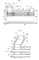
- Fig. 1 shows a heat exchanger .
- Fig. 2 shows deformation in a bellows 6 of the heat exchanger shown in Fig. 1.
- the heat exchanger is provided with a core 3 which is of a multi-plate type, in which: a pair of dish-like metallic plates each provided with a pair of communication holes in its opposite end portions have their peripheral edge portions brought into fluid-tight contact and connected with each other to form an heat exchanger element 12; a plurality of the thus formed elements 12 are stacked together into a pile, and connected with each other through their communication holes.
- a pile thus formed has its top portion covered with an upper end plate 15.
- This upper end plate 15 of the core 3 is provided with a pair of openings in its opposite end portions, in which openings a pair of inlet/outlet pipes 1 are fixedly mounted to project upward as viewed in Fig. 1.
- the above-mentioned pile has its bottom portion covered with a lower end plate having no communication hole, so that the core 3 is formed.
- an outer fin 16 is interposed between adjacent ones of these heat exchanger elements 12.
- Each of the inlet/outlet pipes 1 of the core 3 is constructed as a small-diameter pipe.
- a right-hand one of these inlet/outlet pipes 1 as viewed in Fig. 1 is fixedly mounted in a corresponding one of a pair of through-hole portions 4 of the casing 5 by means of soldering and like fastening means, so that this right-hand one is brought into fluid-tight contact with the corresponding one of the through-hole portions 4 of the casing 5.
- a left-hand one of the inlet/outlet pipes 1 of the core 3 has its upper end portion connected with a lower end portion of the bellows 6 interposed between the left-hand one of the inlet/outlet pipes 1 and a short pipe 10. As shown in Fig.
- this short pipe 10 has its upper end portion brought into fluid-tight contact with a top through-hole portion 4 of a short sleeve portion 7 of the casing 5 and fixedly mounted in this top through-hole portion 4 by means of soldering and like fastening means.
- the short sleeve portion 7 of the casing 5 is provided in an outer peripheral surface of the casing 5 in a position corresponding to that of the left-hand one of the inlet/outlet pipes 1 of the core 3 to project radially outwardly therefrom.
- An inner diameter of the short sleeve portion 7 of the casing 5 is sufficiently larger than an outer diameter of the bellows 6 to permit the bellows 6 to deform laterally.
- a hot oil serving as a first fluid 17 is introduced into the individual heat exchanger elements 12 of the core 3 through a right-hand one of the inlet/outlet pipes 1 of the core 3, as shown in Fig. 1.
- Such a first fluid or hot oil 17 thus passed through the core 3 is then discharged out of the left-hand one of the inlet/outlet pipes 1 of the core 3.
- cold water serving as a second fluid 18 is introduced into the casing 5 from a left-hand inlet opening (not shown), passes through the casing 5, and is then discharged from a right-hand outlet opening (not shown) of the casing 5, wherein heat exchange is performed between the hot oil serving as the first fluid 17 and the cold water serving as the fluid 18.
- a difference in thermal expansion appears between each of the elements 12 of the core 3 and the casing 5.
- Such difference in thermal expansion therebetween is absorbed by deformation of the bellows 6, as shown in Fig. 2.
- deformation of the bellows 6 shown in Fig. 2 is exaggerated for the purpose of illustration.
- An actual amount of such deformation of the bellows 6 is very small in most cases.
- the bellows 6 is capable of absorbing any difference in thermal expansion between the components of the heat exchanger of the present invention to reduce thermal stresses imposed on base portions (i.e., root portions) of the inlet/outlet pipes 1 of the core 3.
- a first embodiment of the heat exchanger of the present invention is shown in Fig. 3. More specifically, in the first embodiment, an inner flange portion 8 of the casing 5 is provided in the root portion of the sleeve-like portion 7 of the casing 5 of the heat exchanger shown in Fig. 1 to form the first embodiment shown in Fig. 3.
- the inner flange portion 8 is sandwiched between: the upper end plate 15 of the core 3; and a flat surface portion (i.e., flange member 9) of a small reservoir portion 11.
- the inner flange portion 8 of the casing 5 is held by holding means 9,15, wherein the holding means 9,15 is constructed of the upper end plate 15 of the core 3 and the flat surface portion (i.e. flange member 9) of the small reservoir portion 11, as is clear from Fig. 3.
- the small reservoir portion 11 is laterally slidable relative to the inner flange portion 8 of the casing 5.
- the sleeve-like portion 7 assumes a circular truncated cone shape. Consequently, in operation, the root portions of the inlet/outlet pipes 1 in the first embodiment of the present invention shown in Fig. 3 are free from any bending moment resulted from a difference in thermal expansion between the components of the heat exchanger.
- the inlet/outlet pipe 1 is also deformed when the bellows 6 is deformed.
- the root portion of the inlet/outlet pipe 1 is subjected to a considerably large amount of bending moment (expressed by the arrow of Fig. 5).
- the holding means 9,15 is capable of effectively minimizing such bending moment.
- Fig. 4 is a second embodiment of the heat exchanger of the present invention, in which the holding means 9,15 is constructed of: the flange member 9 mounted on an outer peripheral portion of the inlet/outlet pipe 1; and the upper end plate 15 of the core 3 to permit the inner flange portion 8 of the casing 5 to laterally slidably move relative to the holding means 9,15.
- the bellows 6 of the heat exchanger of the present invention having the above construction is capable of sufficiently absorbing any difference in thermal expansion between the core 3 and casing 5 even when a difference in length between the core 3 and the casing 5 is produced due to their thermal expansion.
- the heat exchange of the first embodiment of the present invention is provided with the bellows 6 between the top opening portion of the short sleeve portion 7 of the casing 5 and the inlet/outlet pipe 1 of the core 3, it is possible to prevent the bellows 6 from being exposed outward. Further, it is also possible to permit the bellows 6 to be smoothly deformed within the short sleeve portion 7 of the casing 5, which makes it possible to sufficiently absorb any difference in thermal expansion between the core 3 and the casing 5.
- the first embodiment of the heat exchanger of the present invention is provided with the holding means 9,15 in the root portion of the inlet/outlet pipe 1 of the core 3. Since such a holding means 9,15 is slidably movable relative to the inner flange portion 8 of the casing 5, it is possible for the resiliency of such a bellows 6 to minimize any bending moment appearing in the root portion of the inlet/outlet pipe 1 of the core 3, which improves the root portion of the inlet/outlet pipe 1 of the core 3 in reliability.
Landscapes
- Engineering & Computer Science (AREA)
- Physics & Mathematics (AREA)
- Thermal Sciences (AREA)
- Mechanical Engineering (AREA)
- General Engineering & Computer Science (AREA)
- Heat-Exchange Devices With Radiators And Conduit Assemblies (AREA)
Claims (3)
- Echangeur thermique, comprenant :caractérisé en ce queun noyau (3) prévu avec une paire de tuyaux d'entrée/ sortie (1), dans lequel lesdits tuyaux d'entrée/ sortie (1) sont espacés longitudinalement l'un par rapport à l'autre sur une surface périphérique extérieure dudit noyau (3) ;un carter (5) permettant de recevoir dans celui-ci ledit noyau (3), ledit carter (5) étant prévu avec une paire de portions à trous traversants (4) qui sont amenées en contact étanche aux liquides avec lesdits tuyaux d'entrée/ sortie (1) dudit noyau (3), un premier fluide (17) et un deuxième fluide (18) étant introduits dans ledit noyau (3) et ledit carter (5), respectivement, pour effectuer un échange thermique entre ledit premier fluide (17) et ledit deuxième fluide (18) ; etun soufflet (6) intercalé entre au moins l'un desdits tuyaux d'entrée/ sortie (1) dudit noyau (3) et une portion correspondante desdites portions à trous traversants (4) dudit carter (5) pour réaliser un contact étanche aux fluides entre ledit soufflet et chaque élément dudit tuyau desdits tuyaux d'entrée/ sortie (1) dudit noyau (3) et de ladite portion correspondante desdites portions à trous traversants (4) dudit carter (5), ledit soufflet (6) permettant audit tuyau desdits tuyaux d'entrée/ sortie (1) dudit noyau (3) de se déplacer par rapport à ladite portion correspondante desdites portions à trous traversants (4) dudit carter (5) dans une direction radiale de ladite portion correspondante desdites portions à trous traversants (4) dudit carter (5),une portion de manchon court (7) d'un diamètre plus grand que ledit tuyau desdits tuyaux d'entrée/ sortie (1) dudit noyau (3) est prévue dans une position correspondant à celle de ladite portion correspondante desdites portions à trous traversants (4) dudit carter (5) ; la portion d'ouverture supérieure de ladite portion de manchon court (7) dudit carter (5) est amenée en contact étanche aux fluides avec l'une des extrémités opposées dudit soufflet (6), l'autre extrémité desdites extrémités opposées dudit soufflet (6) étant amenée en contact étanche aux fluides avec ledit tuyau desdits tuyaux d'entrée/ sortie (1) dudit noyau (3),
ladite portion de manchon court (7) dudit carter (5) est prévue avec une portion de bride intérieure (8) dans sa portion de fond ; et des moyens de maintien (9, 15) pour maintenir de façon coulissante ladite portion de bride intérieure (8) dudit carter (5) sont prévus dans la portion de fond dudit tuyau desdits tuyaux d'entrée/ sortie (1) dudit noyau (3). - Echangeur thermique selon la revendication 1, dans lequel lesdits moyens de maintien (9, 15) se composent d'un élément de bride (9) et d'une plaque d'extrémité supérieure (15) dudit noyau (3).
- Echangeur thermique selon la revendication 1 ou la revendication 2, dans lequel ladite portion de manchon court (7) dudit carter (5) adopte une forme de cône tronqué circulaire.
Priority Applications (2)
| Application Number | Priority Date | Filing Date | Title |
|---|---|---|---|
| EP00308062A EP1189008B1 (fr) | 2000-09-15 | 2000-09-15 | Echangeur de chaleur |
| DE60006813T DE60006813T2 (de) | 2000-09-15 | 2000-09-15 | Wärmetauscher |
Applications Claiming Priority (1)
| Application Number | Priority Date | Filing Date | Title |
|---|---|---|---|
| EP00308062A EP1189008B1 (fr) | 2000-09-15 | 2000-09-15 | Echangeur de chaleur |
Publications (2)
| Publication Number | Publication Date |
|---|---|
| EP1189008A1 EP1189008A1 (fr) | 2002-03-20 |
| EP1189008B1 true EP1189008B1 (fr) | 2003-11-26 |
Family
ID=8173265
Family Applications (1)
| Application Number | Title | Priority Date | Filing Date |
|---|---|---|---|
| EP00308062A Expired - Lifetime EP1189008B1 (fr) | 2000-09-15 | 2000-09-15 | Echangeur de chaleur |
Country Status (2)
| Country | Link |
|---|---|
| EP (1) | EP1189008B1 (fr) |
| DE (1) | DE60006813T2 (fr) |
Cited By (1)
| Publication number | Priority date | Publication date | Assignee | Title |
|---|---|---|---|---|
| DE102015012505B4 (de) * | 2015-09-24 | 2017-08-03 | Audi Ag | Dichtungsanordnung für eine Anschlussvorrichtung und Anschlussvorrichtung für eine Klimaanlage |
Families Citing this family (6)
| Publication number | Priority date | Publication date | Assignee | Title |
|---|---|---|---|---|
| DE10230852A1 (de) * | 2002-07-04 | 2004-01-22 | Behr Gmbh & Co. | Wärmetauscher, insbesondere Ladeluftkühler für Kraftfahrzeuge |
| DE102005050738A1 (de) * | 2005-10-22 | 2007-04-26 | Modine Manufacturing Co., Racine | Wärmetauscher in Plattenbauweise |
| EP1930680A1 (fr) * | 2006-11-21 | 2008-06-11 | Behr GmbH & Co. KG | Transmetteur thermique de couche doté d'un dispositif de découplage |
| DE202008011555U1 (de) * | 2008-08-28 | 2010-01-07 | Autokühler GmbH & Co. KG | Sammelkasten für einen Ladeluftkühler |
| CN102538520A (zh) * | 2012-02-28 | 2012-07-04 | 上海艾克森集团有限公司 | 一种全焊接板式换热器 |
| DE102015115147B4 (de) * | 2015-09-09 | 2025-03-20 | Volkswagen Aktiengesellschaft | Wärmetauscher und Verfahren zur Herstellung eines solchen Wärmetauschers |
Family Cites Families (7)
| Publication number | Priority date | Publication date | Assignee | Title |
|---|---|---|---|---|
| US3850231A (en) * | 1973-05-24 | 1974-11-26 | Combustion Eng | Lmfbr intermediate heat exchanger |
| DE3341263A1 (de) * | 1983-11-15 | 1985-05-23 | Klöckner-Humboldt-Deutz AG, 5000 Köln | Waermetauscher |
| JPH04340088A (ja) * | 1991-02-04 | 1992-11-26 | Kazumi Seisakusho:Kk | プレートフィン式熱交換器 |
| FR2705769B1 (fr) * | 1993-05-26 | 1995-08-11 | Electricite De France | Echangeur de chaleur pour fluide contaminé. |
| JP3041753B2 (ja) * | 1994-02-16 | 2000-05-15 | 株式会社日立製作所 | プレート式熱交換器 |
| SE506845C2 (sv) * | 1996-06-28 | 1998-02-16 | Alfa Laval Ab | Plattvärmeväxlare med bälgförsett foder till anslutningsrör |
| JP4450887B2 (ja) * | 1999-05-20 | 2010-04-14 | 株式会社ティラド | 熱交換器 |
-
2000
- 2000-09-15 EP EP00308062A patent/EP1189008B1/fr not_active Expired - Lifetime
- 2000-09-15 DE DE60006813T patent/DE60006813T2/de not_active Expired - Lifetime
Cited By (1)
| Publication number | Priority date | Publication date | Assignee | Title |
|---|---|---|---|---|
| DE102015012505B4 (de) * | 2015-09-24 | 2017-08-03 | Audi Ag | Dichtungsanordnung für eine Anschlussvorrichtung und Anschlussvorrichtung für eine Klimaanlage |
Also Published As
| Publication number | Publication date |
|---|---|
| DE60006813D1 (de) | 2004-01-08 |
| EP1189008A1 (fr) | 2002-03-20 |
| DE60006813T2 (de) | 2004-09-23 |
Similar Documents
| Publication | Publication Date | Title |
|---|---|---|
| US6283199B1 (en) | Heat exchanger | |
| EP2257757B2 (fr) | Échangeur de chaleur à plaques | |
| KR101055083B1 (ko) | 열교환 반응기 내에서 열팽창의 악영향을 최소화하는 방법및 장치 | |
| EP2226602B1 (fr) | Tube d'échange de chaleur | |
| US6408941B1 (en) | Folded fin plate heat-exchanger | |
| EP1541955B1 (fr) | Radiateur avec refroidisseur d'huile | |
| GB2281388A (en) | Heat pipe | |
| US5052480A (en) | Pipe for coolant condenser | |
| PL208367B1 (pl) | Płytowy wymiennik ciepła | |
| EP1189008B1 (fr) | Echangeur de chaleur | |
| US20150155465A1 (en) | Thermoelectric device | |
| EP2257758B1 (fr) | Échangeur de chaleur à plaques | |
| US20050039899A1 (en) | Turbulator for heat exchanger | |
| JP3594606B2 (ja) | プレート型熱交換器 | |
| KR20200046195A (ko) | 자동차배열 열전발전장치용 열교환기 | |
| JP2005024109A (ja) | 熱交換器 | |
| KR102511728B1 (ko) | 열교환기 및 열교환기 제작방법 | |
| EP1189009A1 (fr) | Echangeur de chaleur du type empilé | |
| EP0903554B1 (fr) | Plaque d'échange thermique pour échangeur thermique de plaques | |
| WO2001048433A1 (fr) | Echangeur a plaques | |
| JP7418221B2 (ja) | 熱交換器の流路構造、及び熱交換器 | |
| KR0133036B1 (ko) | 열교환기 및 그 제조방법 | |
| EP0502982B1 (fr) | Echangeur de chaleur | |
| KR100425917B1 (ko) | 보일러의 열교환기 고정구조 | |
| KR20100060868A (ko) | 열교환기 |
Legal Events
| Date | Code | Title | Description |
|---|---|---|---|
| PUAI | Public reference made under article 153(3) epc to a published international application that has entered the european phase |
Free format text: ORIGINAL CODE: 0009012 |
|
| AK | Designated contracting states |
Kind code of ref document: A1 Designated state(s): DE FR GB Kind code of ref document: A1 Designated state(s): AT BE CH CY DE DK ES FI FR GB GR IE IT LI LU MC NL PT SE |
|
| AX | Request for extension of the european patent |
Free format text: AL;LT;LV;MK;RO;SI |
|
| 17P | Request for examination filed |
Effective date: 20020722 |
|
| AKX | Designation fees paid |
Free format text: DE FR GB |
|
| 17Q | First examination report despatched |
Effective date: 20021120 |
|
| GRAH | Despatch of communication of intention to grant a patent |
Free format text: ORIGINAL CODE: EPIDOS IGRA |
|
| GRAS | Grant fee paid |
Free format text: ORIGINAL CODE: EPIDOSNIGR3 |
|
| GRAA | (expected) grant |
Free format text: ORIGINAL CODE: 0009210 |
|
| AK | Designated contracting states |
Kind code of ref document: B1 Designated state(s): DE FR GB |
|
| REG | Reference to a national code |
Ref country code: GB Ref legal event code: FG4D |
|
| REF | Corresponds to: |
Ref document number: 60006813 Country of ref document: DE Date of ref document: 20040108 Kind code of ref document: P |
|
| REG | Reference to a national code |
Ref country code: IE Ref legal event code: FG4D |
|
| ET | Fr: translation filed | ||
| PLBE | No opposition filed within time limit |
Free format text: ORIGINAL CODE: 0009261 |
|
| STAA | Information on the status of an ep patent application or granted ep patent |
Free format text: STATUS: NO OPPOSITION FILED WITHIN TIME LIMIT |
|
| 26N | No opposition filed |
Effective date: 20040827 |
|
| REG | Reference to a national code |
Ref country code: IE Ref legal event code: MM4A |
|
| REG | Reference to a national code |
Ref country code: FR Ref legal event code: CD |
|
| PGFP | Annual fee paid to national office [announced via postgrant information from national office to epo] |
Ref country code: GB Payment date: 20120912 Year of fee payment: 13 |
|
| PGFP | Annual fee paid to national office [announced via postgrant information from national office to epo] |
Ref country code: DE Payment date: 20120912 Year of fee payment: 13 Ref country code: FR Payment date: 20120926 Year of fee payment: 13 |
|
| GBPC | Gb: european patent ceased through non-payment of renewal fee |
Effective date: 20130915 |
|
| REG | Reference to a national code |
Ref country code: DE Ref legal event code: R119 Ref document number: 60006813 Country of ref document: DE Effective date: 20140401 |
|
| REG | Reference to a national code |
Ref country code: FR Ref legal event code: ST Effective date: 20140530 |
|
| PG25 | Lapsed in a contracting state [announced via postgrant information from national office to epo] |
Ref country code: GB Free format text: LAPSE BECAUSE OF NON-PAYMENT OF DUE FEES Effective date: 20130915 |
|
| PG25 | Lapsed in a contracting state [announced via postgrant information from national office to epo] |
Ref country code: DE Free format text: LAPSE BECAUSE OF NON-PAYMENT OF DUE FEES Effective date: 20140401 Ref country code: FR Free format text: LAPSE BECAUSE OF NON-PAYMENT OF DUE FEES Effective date: 20130930 |