EP1189018A2 - Système de positionnement à six axes avec espace libre de champs magnétique - Google Patents
Système de positionnement à six axes avec espace libre de champs magnétique Download PDFInfo
- Publication number
- EP1189018A2 EP1189018A2 EP01120844A EP01120844A EP1189018A2 EP 1189018 A2 EP1189018 A2 EP 1189018A2 EP 01120844 A EP01120844 A EP 01120844A EP 01120844 A EP01120844 A EP 01120844A EP 1189018 A2 EP1189018 A2 EP 1189018A2
- Authority
- EP
- European Patent Office
- Prior art keywords
- straight guide
- coordinate
- holding system
- arrangement according
- displacement
- Prior art date
- Legal status (The legal status is an assumption and is not a legal conclusion. Google has not performed a legal analysis and makes no representation as to the accuracy of the status listed.)
- Granted
Links
Images


Classifications
-
- G—PHYSICS
- G03—PHOTOGRAPHY; CINEMATOGRAPHY; ANALOGOUS TECHNIQUES USING WAVES OTHER THAN OPTICAL WAVES; ELECTROGRAPHY; HOLOGRAPHY
- G03F—PHOTOMECHANICAL PRODUCTION OF TEXTURED OR PATTERNED SURFACES, e.g. FOR PRINTING, FOR PROCESSING OF SEMICONDUCTOR DEVICES; MATERIALS THEREFOR; ORIGINALS THEREFOR; APPARATUS SPECIALLY ADAPTED THEREFOR
- G03F7/00—Photomechanical, e.g. photolithographic, production of textured or patterned surfaces, e.g. printing surfaces; Materials therefor, e.g. comprising photoresists; Apparatus specially adapted therefor
- G03F7/70—Microphotolithographic exposure; Apparatus therefor
- G03F7/70691—Handling of masks or workpieces
- G03F7/707—Chucks, e.g. chucking or un-chucking operations or structural details
-
- G—PHYSICS
- G03—PHOTOGRAPHY; CINEMATOGRAPHY; ANALOGOUS TECHNIQUES USING WAVES OTHER THAN OPTICAL WAVES; ELECTROGRAPHY; HOLOGRAPHY
- G03F—PHOTOMECHANICAL PRODUCTION OF TEXTURED OR PATTERNED SURFACES, e.g. FOR PRINTING, FOR PROCESSING OF SEMICONDUCTOR DEVICES; MATERIALS THEREFOR; ORIGINALS THEREFOR; APPARATUS SPECIALLY ADAPTED THEREFOR
- G03F7/00—Photomechanical, e.g. photolithographic, production of textured or patterned surfaces, e.g. printing surfaces; Materials therefor, e.g. comprising photoresists; Apparatus specially adapted therefor
- G03F7/70—Microphotolithographic exposure; Apparatus therefor
- G03F7/70691—Handling of masks or workpieces
- G03F7/70716—Stages
-
- H—ELECTRICITY
- H10—SEMICONDUCTOR DEVICES; ELECTRIC SOLID-STATE DEVICES NOT OTHERWISE PROVIDED FOR
- H10P—GENERIC PROCESSES OR APPARATUS FOR THE MANUFACTURE OR TREATMENT OF DEVICES COVERED BY CLASS H10
- H10P72/00—Handling or holding of wafers, substrates or devices during manufacture or treatment thereof
- H10P72/50—Handling or holding of wafers, substrates or devices during manufacture or treatment thereof for positioning, orientation or alignment
-
- H—ELECTRICITY
- H01—ELECTRIC ELEMENTS
- H01J—ELECTRIC DISCHARGE TUBES OR DISCHARGE LAMPS
- H01J2237/00—Discharge tubes exposing object to beam, e.g. for analysis treatment, etching, imaging
- H01J2237/20—Positioning, supporting, modifying or maintaining the physical state of objects being observed or treated
- H01J2237/202—Movement
Definitions
- the invention relates to an arrangement for positioning substrates, in particular for positioning wafers within a facility, those for exposing the substrates and / or for measuring on the substrates is provided by means of radiation under high vacuum conditions.
- the process for wafer exposure using an ion beam requires a wafer table for positioning the wafer in relation to the illuminating beam.
- the exposure process itself requires an ion source and an electrostatic column Lenses for focusing the beam. This results in Special features for wafer positioning.
- the sensitivity of the ion beam against electrostatic and magnetic interference the elimination of possible sources of interference in the immediate vicinity of the exposure location and the careful shielding of such (for example, the drives of the wafer table) in the wider area.
- non-optical exposure processes usually work under high vacuum conditions (here 10 -6 mbar). This leads to problems of outgassing materials and the thermal stress on power components.
- the drives used must therefore be selected to optimize their power loss and, if possible, be provided with cooling.
- the use of non-vacuum compatible materials is prohibited. Friction and wear must be minimized or even eliminated.
- the wafer table should enable the exposure of wafers of different sizes, in particular 300 mm wafers, and for this purpose have a travel range of at least 310 ⁇ 310 mm 2 .
- movements of the wafer must be realized in as many degrees of freedom as possible.
- the aim is to achieve positional accuracy and position accuracy in the submicrometer or microrad range.
- the measurement of optical reference marks on the wafer surface, which are required for coupling the ion beam to the wafer require at least partially uniform traversing speeds with a deviation of less than 2%.
- the wafer table should enable a high throughput of exposed wafers per unit of time (throughput) and therefore have good dynamic properties.
- the prior art offers no comparable systems for such different properties such as operation in high vacuum, vertical working level of the positioning system, compensation of the weight of the rotor assembly through magnetic forces and shielding of magnetic fields are designed for a residual value in the nano-Tesla range and a combination combine these solutions in one device.
- the object of the invention is based on this prior art in developing the positioning systems so that a higher one Positioning accuracy as a prerequisite for exact exposure and measurement of ever finer structures even under high vacuum becomes.
- an arrangement for positioning substrates for this of the type described in the introduction which comprises: one on one Straight guide system for holding the substrate, the direction of guidance of the straight guide parallel or substantially aligned parallel to the coordinate Y of a spatial coordinate system X, Y, Z. is; Drives for changing the inclination of the guide direction relative to the coordinate Y; Drives for rotating the straight guide including the holding system around the guide direction and drives for parallel displacement of the straight guide including the holding system in the direction of the coordinate X, in Direction of the coordinate Y and / or in the direction of the coordinate Z.
- the invention is a novel six-axis positioning system with a magnetic field-free Space, suitable for use in high vacuum for flat substrates, especially wafers, in connection with exposure systems and measuring devices using charged particles for irradiation, at which high Requirements for avoiding disturbing magnetic fields in the particle beam range exist.
- This positioning system is characterized by high precision and dynamics in all axes of motion as well as high rigidity out.
- each drive unit with a stator and a rotor variable air gap to each other, the rotor in the direction X slidable and each runner with the opposite end of the straight line is connected to the holding system.
- Each stator preferably contains the drive coils for use under vacuum of a linear motor acting in the X direction and ferromagnetic guideways in the Z and Y directions.
- the rotor then carries the permanent magnetic circuit of the linear motor and electromagnetic actuators where the ferromagnetic guideway of the stator part of the respective magnetic circuit is, whereby the necessary storage and driving forces between the Guideways of the stator and the rotor are generated without contact.
- each rotor is equipped with four electromagnetic actuators equipped in pairs on the respective Stator face each other, with the two pairs of actuators on each Unit have a distance to each other measured in direction X and so can be controlled that either a balance of forces in a desired Position or acceleration forces required for changes in position be generated. This creates a non-contact magnetic guide realized in the Z direction with adjustable air gap.
- At least a fifth such an electromagnetic actuator is provided, with control this actuator influences the air gaps measured in the Y direction he follows. This is also a non-contact magnetic guide in the direction Y realized.
- the guideway of the straight guide and the holding system are preferred made of non-magnetic material.
- a stepper motor its rotational movement via a cable system into the linear movement the holding system is changed along the straight line, and there are facilities provided for clamping the holding system in a predetermined Sliding position on the straight guide, for example in the form of Piezo actuators can be formed.
- the holding system should advantageously consist essentially of one made of Zerodur Manufactured wafer chuck for placing and electrostatically holding the exposing or measuring substrates and made of a titanium Stand for holding the wafer chuck.
- the straight line should advantageously be made of ceramic, the frame over ungreased Ceramic ball bearing is coupled to the straight guide.
- the holding system preferably the wafer chuck, Mirror surfaces worked on, which measure the displacement positions achieved in each case serve with the intended interferometer arrangements.
- three capacitive Sensors are provided which measure the distance of the substrate surface from one Measure the specified reference plane.
- Means for magnetic shielding of the areas in which the Radiation used for exposure and / or measurement runs Means for magnetic shielding of the areas in which the Radiation used for exposure and / or measurement runs.
- This shield protects this radiation against the influence of disturbing magnetic fields, in particular against the magnetic fields of the drives to change the inclination, rotation and / or parallel displacement.
- the shielding can take the form of multi-layer shielding walls be, the shielding walls being between each other displaceable assemblies are located, laterally offset from each other, so that meandering magnetic seals are created.
- the assemblies of the linear motors should be fixed to the frame be chilled.
- the movable assemblies can also be provided the linear motors, especially the rotors, with a heat radiating To provide surface coating.
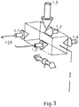
- the straight guide 3 is including the holding system 4 by means of the two drive units 1, 2 in a direction parallel to the substrate surface and with little elastic flexibility in all directions guided and driven, as will be shown below.
- the drive units 1, 2 can of course one take any position in the room, but a horizontal orientation is preferred.
- the direction of movement of the holding system 4 is along the straight guide 3 vertical, d. H. aligned in the direction of gravity.
- the ceramic profile of the straight guide 3 serves as a guide element and can at the same time pick up the drive elements that trigger the displacement movement of the holding system 4 are required (not shown in the drawing).
- the two drive units 1, 2 are magnetic in four degrees of freedom guided. In the remaining two degrees of freedom, the tour takes place through the Linear motors where there are no mechanical points of contact between Stator 5, 6 and rotor 7, 8 exist.
- the highly dynamic fine adjustment movement is controlled by controlling the air gap of the magnetic guides in degrees of freedom Y, Z, RX, RY and the positioning of the linear motors in the Degrees of freedom X, RZ realized within the range of motion.
- the position of the runners 7, 8 is measured independently by means of two plane mirror interferometers 9, 10 working from one another.
- capacitive Sensors are provided in common with the plane mirror interferometers 9, 10 for measuring the position of the holding system 4 can be used.
- Magnetic shielding walls 11 are also provided for each drive unit to protect the particle beam area from disturbing magnetic fields, which is designed in multiple layers, the one for the movement transmission necessary slots in the individual layers laterally offset from each other lie and thus creates a meandering magnetic seal, which a rigid connection of the rotor 7, 8 with the magnetic field-free holding system 4 enables. 2 shows the magnetic shielding walls 11 for clarity because only indicated in the drive unit 2.
- Linear motors and magnetic bearings are advantageously outside the particle beam range, d. H. outside the area where the exposure and / or measurement used radiation, arranged and not mounted directly on the holding system 4 for the substrate. They are around this particle beam area arranged around, with a symmetrical arrangement is preferred.
- FIG 2 it can also be seen that the holding system 4 with a wafer chuck 12 for receiving the wafer with the wafer surface aligned vertically Is provided.
- a stepper motor drive 13 enables a (rough) Positioning over a delivery range of approximately 320 mm in the vertical y-axis.
- the wafer chuck 12 on which the wafer is electrostatically held is manufactured with high precision from temperature-stable Zerodur.
- At the wafer chuck 12 are mirrored on the sides, which are used to determine and control the Chuck position with a 6-beam laser interferometer arrangement 14 (resolution 0.6 nm) in all degrees of freedom except the Z coordinate.
- the location of the wafer to coordinate Z is directly on the wafer surface with the help determined by three high-precision capacitive sensors (not shown).
- the Measurement signals thus obtained are also referred to below as "global" signals referred to as the immediate position of the wafer to be exposed represent.
- the wafer chuck 12 is coupled to a frame made of titanium profiles without tension, which is vertical and with the help of non-lubricated ceramic ball bearings is guided along the ceramic profile of the straight guide 3.
- the coupling the vertical movement for the holding system 4 with the wafer chuck 12, as already explained, takes place via a fast stepper motor 13 driven cable.
- the frame can be in any vertical Y coordinate in the range of ⁇ 160 mm with an accuracy of approx. ⁇ 10 ⁇ m can be clamped. This results in repeatability in the range of a few ⁇ m / ⁇ rad in all other coordinates. After reaching the desired vertical position of the wafer the rope of the cable relaxes to influence it on the drive units 1, 2 to minimize.
- the electrodynamic direct drives provided in the drive units 1, 2 or linear motors are magnetically guided and triple shielded (Shielding walls 11). They enable a highly precise horizontal X movement of ⁇ 160 mm, which with the help of the two plane mirror interferometers 9, 10 measured with a resolution of 5 nm on the upper and lower linear motor becomes. A controlled asynchronous process of the two linear motors leads to rotation RZ.
- Each drive unit 1, 2 has a total of five electromagnetic actuators 1.1, 1.2, 1.3, 1.4, 1.5 or 2.1, 2.2, 2.3, 2.4, 2.5, each of which four to implement adjustment movements in the Z direction (the actuators 1.1, 1.2, 1.3, 1.4 or 2.1, 2.2, 2.3, 2.4) and one each (the actuators 1.5 or 2.5) are used to implement adjustment movements in the Y direction.
- the actuators 1.1, 1.2, 1.3, 1.4 and 1.5 in the Drive unit 1 shown.
- Each of these actuators 1.1, 1.2, 1.3, 1.4, 1.5 or 2.1, 2.2, 2.3, 2.4, 2.5 has its own, "local" capacitive measuring system for high-precision measurement of the air gap between the stator and the rotor or between the active surface of the actuator and the guide surface on the stator in the range of ⁇ 0.5 mm at a resolution of 20 nm.
- the air gap enables movement in the coordinates Y, Z, RY and RX.
- the actuators 1.5 and 2.5 are of hybrid design; H. she have built-in permanent magnets, the majority of which are lossless Compensate part of the weight to be moved mass of approx. 50 kg. Unless the Y coordinate in other embodiments of the invention, but that the Z coordinate should point in the direction of gravity are Actuators 1.1, 1.2, 1.3, 1.4 or 2.1, 2.2, 2.3, 2.4 designed in this sense.
- FIGS Degrees of freedom X, Y, Z, RX, RY, RZ The realization of the adjustment movements in FIGS Degrees of freedom X, Y, Z, RX, RY, RZ explained. They can be recognized symbolically straight guide shown 3, the drive unit 1 with the stator 5, the Rotor 7 and the actuators 1.1, 1.2, 1.3, 1.4, 1.5 and the drive unit 2 with the stator 6, the rotor 8 and the actuators 2.1, 2.2, 2.3, 2.4, 2.5.
- the Actuators 1.1, 1.2, 1.3, 1.4 are for changing those measured in the Z direction Width of the air gap between the stator 5 and the rotor 7 on the Drive unit 1 provided, the actuators 2.1, 2.2, 2.3, 2.4 for change the width of the air gap between the stator measured in direction Z. 6 and the rotor 8 on the drive unit 2.
- the actuator 1.5 on the drive unit 1 and the actuator 2.5 on the drive unit 2 are used for the change the width of the air gaps measured in the
- a self-contained unit can be moved with high precision in all six degrees of freedom. she is magnetically guided and "floats" almost without contact (apart from electrical leads and the influence of the cable) in the room largely free of friction and wear.
- the drives as potential sources of interference are relatively far away with more than half a meter from the place of exposure.
- the field originating from the drives can with a suitable, in this case triple shielding be drastically reduced.
- a wide area around the exposing ion beam is iron-free This minimizes exposure distortion.
- the permanent magnet based Weight compensation in the magnetic guide can electromagnetic actuators of the guide with almost zero static Electricity can be operated, resulting in a low power conversion and thus leads to a slight heating of the drives in a vacuum.
- the coils in the direct drives for fast and precise horizontal positioning are statically mounted and therefore easy to cool.
- the drive units 1, 2 are advantageously each in a housing from steel. This steel case is also the first layer of the magnetic shielding; two more layers of MuMetal are applied, after the drive units 1, 2 are fully installed and aligned are. Each shield comes with a labyrinth seal for that from the drive units 1, 2 outgoing magnetic interference field provided by the the movement is led outwards. Try in a shielding chamber have shown that the three-layer shielding from a drive emerging magnetic field at 10 nT (static) and 5 pT (dynamic) can be reduced at the exposure location.
- the electromagnets are almost zero static electricity are operated (apart from small, constantly to be applied Forces for moment and residual weight compensation) is the average power consumption much lower. It is a total approximately 0.5 W in the entire magnetic guide of a direct drive. The estimated excess temperature in the immediate vicinity the coils of the electromagnets is 3K, which extends across the entire drive reduced to ⁇ 1 K. Because both the actuator and the stator are in direct drive are provided with a black aluminum oxide layer, at least partly a delivery of the power consumed in the tours Radiant heat to the cooled stator.
- this example of a positioning system shows a magnetic one guided, electrodynamically driven high-precision vertical wafer table, the very low magnetic interference fields emitted and for use in High vacuum is suitable.
- This table despite the difficult system environment Positional rest and accuracy in the sub- ⁇ m or ⁇ rad range and also achieves a particularly high synchronization of the wafer table.
Landscapes
- Physics & Mathematics (AREA)
- General Physics & Mathematics (AREA)
- Exposure And Positioning Against Photoresist Photosensitive Materials (AREA)
- Container, Conveyance, Adherence, Positioning, Of Wafer (AREA)
- Exposure Of Semiconductors, Excluding Electron Or Ion Beam Exposure (AREA)
- Electron Beam Exposure (AREA)
Applications Claiming Priority (2)
| Application Number | Priority Date | Filing Date | Title |
|---|---|---|---|
| DE10046144 | 2000-09-15 | ||
| DE10046144 | 2000-09-15 |
Publications (3)
| Publication Number | Publication Date |
|---|---|
| EP1189018A2 true EP1189018A2 (fr) | 2002-03-20 |
| EP1189018A3 EP1189018A3 (fr) | 2003-04-02 |
| EP1189018B1 EP1189018B1 (fr) | 2009-02-25 |
Family
ID=7656655
Family Applications (1)
| Application Number | Title | Priority Date | Filing Date |
|---|---|---|---|
| EP01120844A Expired - Lifetime EP1189018B1 (fr) | 2000-09-15 | 2001-08-30 | Système de positionnement à six axes avec espace libre de champs magnétique |
Country Status (4)
| Country | Link |
|---|---|
| US (1) | US6639225B2 (fr) |
| EP (1) | EP1189018B1 (fr) |
| JP (1) | JP2002184838A (fr) |
| DE (2) | DE50114723D1 (fr) |
Cited By (4)
| Publication number | Priority date | Publication date | Assignee | Title |
|---|---|---|---|---|
| EP1286221A3 (fr) * | 2001-08-20 | 2005-02-09 | Canon Kabushiki Kaisha | Appareil de positionnement |
| US6891600B2 (en) | 2002-06-12 | 2005-05-10 | Asml Netherlands B.V. | Lithographic apparatus and device manufacturing method |
| WO2012146709A3 (fr) * | 2011-04-29 | 2013-06-06 | Physik Instrumente (Pi) Gmbh & Co. Kg | Dispositif de positionnement à haute résolution |
| CN115355813A (zh) * | 2022-10-21 | 2022-11-18 | 北京科技大学 | 一种高精度三轴无磁测试转台系统 |
Families Citing this family (20)
| Publication number | Priority date | Publication date | Assignee | Title |
|---|---|---|---|---|
| US7509270B1 (en) | 1992-12-09 | 2009-03-24 | Discovery Communications, Inc. | Electronic Book having electronic commerce features |
| US7861166B1 (en) | 1993-12-02 | 2010-12-28 | Discovery Patent Holding, Llc | Resizing document pages to fit available hardware screens |
| US7865567B1 (en) | 1993-12-02 | 2011-01-04 | Discovery Patent Holdings, Llc | Virtual on-demand electronic book |
| US6638226B2 (en) * | 2001-09-28 | 2003-10-28 | Teratech Corporation | Ultrasound imaging system |
| JP2004146492A (ja) * | 2002-10-23 | 2004-05-20 | Canon Inc | Euv露光装置 |
| JP2003244927A (ja) * | 2002-02-18 | 2003-08-29 | Yaskawa Electric Corp | リニアモータ及びそれを有するステージ装置 |
| US6888289B2 (en) * | 2002-07-16 | 2005-05-03 | Baldor Electric Company | Multi-axes, sub-micron positioner |
| US20040145751A1 (en) * | 2003-01-28 | 2004-07-29 | Binnard Michael B. | Square wafer chuck with mirror |
| JP2005005393A (ja) * | 2003-06-10 | 2005-01-06 | Canon Inc | ステージ装置、露光装置、およびデバイス製造方法 |
| JP2005253179A (ja) * | 2004-03-03 | 2005-09-15 | Canon Inc | 位置決め装置、露光装置およびデバイス製造方法 |
| JP4447949B2 (ja) * | 2004-03-25 | 2010-04-07 | キヤノン株式会社 | 位置決め装置の初期化方法、露光装置およびデバイス製造方法 |
| FR2881351B1 (fr) * | 2005-02-01 | 2009-01-16 | Linac Technologies Sas Soc Par | Installation et procede pour la sterilisation d'objets par bombardement d'electrons a faible energie |
| TWI359344B (en) * | 2008-03-25 | 2012-03-01 | Univ Nat Taiwan | A six degree of freedom precise positioning system |
| NL2003776A (en) | 2008-12-31 | 2010-07-01 | Asml Holding Nv | Linear motor magnetic shield apparatus. |
| CN102175133B (zh) * | 2011-02-25 | 2012-07-18 | 清华大学 | 全局金属膜厚度测量装置 |
| US9500468B2 (en) | 2014-08-25 | 2016-11-22 | Board Of Trustees Of Michigan State University | Scanning interferometry technique for through-thickness evaluation in multi-layered transparent structures |
| DE102014224221A1 (de) * | 2014-11-27 | 2016-06-02 | Carl Zeiss Smt Gmbh | Positions-Messeinrichtung und Verfahren zur Ermittlung von Positionen eines Messobjekts |
| JP6506153B2 (ja) * | 2015-10-27 | 2019-04-24 | 株式会社Screenホールディングス | 変位検出装置および変位検出方法ならびに基板処理装置 |
| CN105655494B (zh) * | 2016-03-18 | 2018-08-24 | 深圳市华星光电技术有限公司 | 有机发光二极管的基底及其制作方法、有机发光二极管 |
| WO2019211123A1 (fr) | 2018-05-02 | 2019-11-07 | Asml Netherlands B.V. | Appareil à faisceau électronique |
Family Cites Families (7)
| Publication number | Priority date | Publication date | Assignee | Title |
|---|---|---|---|---|
| US5139383A (en) * | 1991-07-23 | 1992-08-18 | Huntington Mechanical Laboratories, Inc. | Device for positioning objects within a sealed chamber |
| US5528118A (en) * | 1994-04-01 | 1996-06-18 | Nikon Precision, Inc. | Guideless stage with isolated reaction stage |
| JPH10112433A (ja) * | 1996-10-04 | 1998-04-28 | Nikon Corp | 除振装置及び露光装置 |
| JP3963410B2 (ja) * | 1997-04-22 | 2007-08-22 | キヤノン株式会社 | 位置決め装置およびこれを用いた露光装置 |
| JP2000243693A (ja) * | 1999-02-23 | 2000-09-08 | Nikon Corp | ステージ装置及び露光装置 |
| DE60032568T2 (de) * | 1999-12-01 | 2007-10-04 | Asml Netherlands B.V. | Positionierungsapparat und damit versehener lithographischer Apparat |
| TW546551B (en) * | 1999-12-21 | 2003-08-11 | Asml Netherlands Bv | Balanced positioning system for use in lithographic apparatus |
-
2001
- 2001-08-30 DE DE50114723T patent/DE50114723D1/de not_active Expired - Lifetime
- 2001-08-30 DE DE10142489A patent/DE10142489A1/de not_active Ceased
- 2001-08-30 EP EP01120844A patent/EP1189018B1/fr not_active Expired - Lifetime
- 2001-09-13 JP JP2001277353A patent/JP2002184838A/ja active Pending
- 2001-09-14 US US09/951,762 patent/US6639225B2/en not_active Expired - Fee Related
Cited By (9)
| Publication number | Priority date | Publication date | Assignee | Title |
|---|---|---|---|---|
| EP1286221A3 (fr) * | 2001-08-20 | 2005-02-09 | Canon Kabushiki Kaisha | Appareil de positionnement |
| US6954258B2 (en) | 2001-08-20 | 2005-10-11 | Canon Kabushiki Kaisha | Positioning apparatus |
| EP1947512A3 (fr) * | 2001-08-20 | 2011-08-31 | Canon Kabushiki Kaisha | Appareil de positionnement et appareil d'exposition, procédé de fonctionnement d'un appareil de positionnement et procédé de fabrication de dispositif |
| US6891600B2 (en) | 2002-06-12 | 2005-05-10 | Asml Netherlands B.V. | Lithographic apparatus and device manufacturing method |
| EP1372035A3 (fr) * | 2002-06-12 | 2006-08-02 | ASML Netherlands B.V. | Appareil lithographique et procédé pour la production d'un dispositif |
| WO2012146709A3 (fr) * | 2011-04-29 | 2013-06-06 | Physik Instrumente (Pi) Gmbh & Co. Kg | Dispositif de positionnement à haute résolution |
| US9479040B2 (en) | 2011-04-29 | 2016-10-25 | Physik Instrumente (Pi) Gmbh & Co. Kg | High-resolution positioning device |
| CN115355813A (zh) * | 2022-10-21 | 2022-11-18 | 北京科技大学 | 一种高精度三轴无磁测试转台系统 |
| CN115355813B (zh) * | 2022-10-21 | 2023-03-24 | 北京科技大学 | 一种高精度三轴无磁测试转台系统 |
Also Published As
| Publication number | Publication date |
|---|---|
| DE10142489A1 (de) | 2002-04-04 |
| JP2002184838A (ja) | 2002-06-28 |
| US6639225B2 (en) | 2003-10-28 |
| EP1189018A3 (fr) | 2003-04-02 |
| DE50114723D1 (de) | 2009-04-09 |
| EP1189018B1 (fr) | 2009-02-25 |
| US20020079461A1 (en) | 2002-06-27 |
Similar Documents
| Publication | Publication Date | Title |
|---|---|---|
| EP1189018B1 (fr) | Système de positionnement à six axes avec espace libre de champs magnétique | |
| DE10025589B4 (de) | Bühne für Ladungsteilchen-Mikroskopiesystem | |
| EP1286131B1 (fr) | Table de mesure de coordonnées et machine de mesure de coordonnées | |
| DE69717975T2 (de) | In zwei richtungen ausgewogenes positioniergerät, sowie lithographisches gerät mit einem solchen positioniergerät | |
| EP3734650B1 (fr) | Procédé et dispositif d'alignement des substrats | |
| DE60114397T2 (de) | Verfahren und vorrichtung zur korrektur von abbe fehlern | |
| DE69605337T2 (de) | Positionierungssystem und Verfahren und Apparat zur Herstellung einer Vorrichtung | |
| DE69709440T2 (de) | Tragvorrichtung unter Verwendung magnetische Energie | |
| DE60032568T2 (de) | Positionierungsapparat und damit versehener lithographischer Apparat | |
| DE69610288T2 (de) | Positioniervorrichtung mit kraftantriebssystem für kompensation von schwerpunktsverschiebungen | |
| DE60222039T2 (de) | Lithographisches Gerät mit Doppelisoliersystem und Verfahren zur Konfigurierung desselben | |
| DE69606620T2 (de) | Stellvorrichtung mit einem schwingungsfreien objekttisch | |
| DE10036217A1 (de) | Gleitvorrichtung sowie ein zugehöriger Tischmechanismus zur Verwendung im Vakuum | |
| US7002668B2 (en) | Stage positioning unit for photo lithography tool and for the like | |
| EP3593379B1 (fr) | Support de substrat électrostatique | |
| DE4209557C2 (de) | Senkrechte XY-Bühne | |
| DE69306192T2 (de) | Getriebemechanismus sowie Positioniereinrichtung mit einem derartigen Getriebemechanismus und Lithographieeinrichtung mit einer derartigen Positioniereinrichtung | |
| DE68911084T2 (de) | Sequenzvorrichtung zur Bildung von Schaltkreisen. | |
| US7084538B2 (en) | Bearing assembly, stage device using same, and exposure apparatus using same | |
| US6794660B2 (en) | Long stroke mover for a stage assembly | |
| WO2023110113A1 (fr) | Procédé et dispositif d'alignement d'un substrat | |
| US6781138B2 (en) | Positioning stage with stationary actuators | |
| DE19853588B4 (de) | Halteeinrichtung für ein Substrat | |
| EP1486829A2 (fr) | Système porte-objet, appareil d'exposition et méthode de fabrication d'un dispositif | |
| EP4449486B1 (fr) | Dispositif et procédé de réglage d'un moyen de détection |
Legal Events
| Date | Code | Title | Description |
|---|---|---|---|
| PUAI | Public reference made under article 153(3) epc to a published international application that has entered the european phase |
Free format text: ORIGINAL CODE: 0009012 |
|
| AK | Designated contracting states |
Kind code of ref document: A2 Designated state(s): AT BE CH CY DE DK ES FI FR GB GR IE IT LI LU MC NL PT SE TR |
|
| AX | Request for extension of the european patent |
Free format text: AL;LT;LV;MK;RO;SI |
|
| PUAL | Search report despatched |
Free format text: ORIGINAL CODE: 0009013 |
|
| AK | Designated contracting states |
Kind code of ref document: A3 Designated state(s): AT BE CH CY DE DK ES FI FR GB GR IE IT LI LU MC NL PT SE TR |
|
| AX | Request for extension of the european patent |
Extension state: AL LT LV MK RO SI |
|
| RIC1 | Information provided on ipc code assigned before grant |
Ipc: 7G 03F 7/20 B Ipc: 7G 01B 11/00 B Ipc: 7H 01L 21/00 B Ipc: 7G 01B 11/27 A |
|
| 17P | Request for examination filed |
Effective date: 20030912 |
|
| AKX | Designation fees paid |
Designated state(s): DE FR GB |
|
| GRAP | Despatch of communication of intention to grant a patent |
Free format text: ORIGINAL CODE: EPIDOSNIGR1 |
|
| GRAS | Grant fee paid |
Free format text: ORIGINAL CODE: EPIDOSNIGR3 |
|
| GRAA | (expected) grant |
Free format text: ORIGINAL CODE: 0009210 |
|
| AK | Designated contracting states |
Kind code of ref document: B1 Designated state(s): DE FR GB |
|
| REG | Reference to a national code |
Ref country code: GB Ref legal event code: FG4D Free format text: NOT ENGLISH |
|
| REF | Corresponds to: |
Ref document number: 50114723 Country of ref document: DE Date of ref document: 20090409 Kind code of ref document: P |
|
| PLBE | No opposition filed within time limit |
Free format text: ORIGINAL CODE: 0009261 |
|
| STAA | Information on the status of an ep patent application or granted ep patent |
Free format text: STATUS: NO OPPOSITION FILED WITHIN TIME LIMIT |
|
| 26N | No opposition filed |
Effective date: 20091126 |
|
| GBPC | Gb: european patent ceased through non-payment of renewal fee |
Effective date: 20090830 |
|
| REG | Reference to a national code |
Ref country code: FR Ref legal event code: ST Effective date: 20100430 |
|
| PG25 | Lapsed in a contracting state [announced via postgrant information from national office to epo] |
Ref country code: FR Free format text: LAPSE BECAUSE OF NON-PAYMENT OF DUE FEES Effective date: 20090831 |
|
| PG25 | Lapsed in a contracting state [announced via postgrant information from national office to epo] |
Ref country code: GB Free format text: LAPSE BECAUSE OF NON-PAYMENT OF DUE FEES Effective date: 20090830 |
|
| PGFP | Annual fee paid to national office [announced via postgrant information from national office to epo] |
Ref country code: DE Payment date: 20130821 Year of fee payment: 13 |
|
| REG | Reference to a national code |
Ref country code: DE Ref legal event code: R119 Ref document number: 50114723 Country of ref document: DE |
|
| REG | Reference to a national code |
Ref country code: DE Ref legal event code: R119 Ref document number: 50114723 Country of ref document: DE Effective date: 20150303 |
|
| PG25 | Lapsed in a contracting state [announced via postgrant information from national office to epo] |
Ref country code: DE Free format text: LAPSE BECAUSE OF NON-PAYMENT OF DUE FEES Effective date: 20150303 |