EP1189076A2 - Méthode de localisation d'objets et dispositif de détection - Google Patents
Méthode de localisation d'objets et dispositif de détection Download PDFInfo
- Publication number
- EP1189076A2 EP1189076A2 EP01116125A EP01116125A EP1189076A2 EP 1189076 A2 EP1189076 A2 EP 1189076A2 EP 01116125 A EP01116125 A EP 01116125A EP 01116125 A EP01116125 A EP 01116125A EP 1189076 A2 EP1189076 A2 EP 1189076A2
- Authority
- EP
- European Patent Office
- Prior art keywords
- voltage
- detector device
- coil
- primary side
- secondary side
- Prior art date
- Legal status (The legal status is an assumption and is not a legal conclusion. Google has not performed a legal analysis and makes no representation as to the accuracy of the status listed.)
- Withdrawn
Links
Images

Classifications
-
- G—PHYSICS
- G01—MEASURING; TESTING
- G01V—GEOPHYSICS; GRAVITATIONAL MEASUREMENTS; DETECTING MASSES OR OBJECTS; TAGS
- G01V3/00—Electric or magnetic prospecting or detecting; Measuring magnetic field characteristics of the earth, e.g. declination, deviation
- G01V3/08—Electric or magnetic prospecting or detecting; Measuring magnetic field characteristics of the earth, e.g. declination, deviation operating with magnetic or electric fields produced or modified by objects or geological structures or by detecting devices
- G01V3/10—Electric or magnetic prospecting or detecting; Measuring magnetic field characteristics of the earth, e.g. declination, deviation operating with magnetic or electric fields produced or modified by objects or geological structures or by detecting devices using induction coils
- G01V3/104—Electric or magnetic prospecting or detecting; Measuring magnetic field characteristics of the earth, e.g. declination, deviation operating with magnetic or electric fields produced or modified by objects or geological structures or by detecting devices using induction coils using several coupled or uncoupled coils
- G01V3/105—Electric or magnetic prospecting or detecting; Measuring magnetic field characteristics of the earth, e.g. declination, deviation operating with magnetic or electric fields produced or modified by objects or geological structures or by detecting devices using induction coils using several coupled or uncoupled coils forming directly coupled primary and secondary coils or loops
Definitions
- the invention relates to a method for locating objects with a detector device in which on a primary side of the detector device an oscillator with a resonant circuit Excites transmitter coil and the transmitter coil an electromagnetic Alternating field emits and in which on a secondary side Detector device in a receiving coil an electromagnetic Alternating field is induced.
- the invention further relates to a detector device with a primary side, which is an oscillator and has a transmitter coil, and a secondary side, which has a receiving coil.
- the generic method and the generic device are components of transmitter-receiver systems, which are also called TR systems (transmitters / receivers).
- TR systems transmitter / receivers
- an electromagnetic coil is used by a transmitter Alternating field emitted, which from a receiving coil is recorded.
- an object representing the formation of the electromagnetic Alternating field for example through the creation of eddy currents in the object is also influenced by the receiving coil received alternating electromagnetic field influenced. From the changed induced in the receiving coil The tension can thus be attributed to the presence of an object conclude.
- it is desirable to use the direct Influence of the transmitter coil on that detected in the receiver coil To minimize the signal in order to reduce the detection sensitivity of the System increase.
- EP 0 957 377 A2 describes a device and a method for locating metal parts. Here is the minimization the direct influence of the transmitter coil on the receiver coil by the relative spatial position of the coil axes. If the planes of the transmitter coil and the receiver coil form an angle of Have 90 ° to each other, largely decouples of the coils instead.
- FIG. 5 Another example of a known TR system is shown in FIG. 5 shown schematically.
- the arrangement comprises an oscillator 112, which two transmitter coils 114, 114 'for sending electromagnetic Stimulates fields.
- the two transmitter coils 114, 114 ' are switched against each other.
- the output voltage of the receiver coil is from amplified by an amplifier 126.
- the receiver coil 116 is of opposite phase Voltages applied by the transmitter coils. On in this way the direct influence is compensated of the transmitter coils 114, 114 'onto the receiver coil.
- this arrangement has the disadvantage that the antiphase of the Transmitting coils 114, 114 'emitted electromagnetic fields work "against each other" and thereby in their training hinder. This way, for example, the range of such a system.
- the object of the invention is to further develop the generic method and the generic detector device in such a way that, with a simple mechanical and electrical structure and good electrical stability, it is possible to work with high detection sensitivity.
- the invention builds on the generic method on that the transmitter coil and the receiver coil are spatially separated are arranged so that a continuous Voltage transformation on the receiving coil takes place from that the primary side and the secondary side two comparison voltages that a differential voltage is obtained from the reference voltages is obtained and that the differential voltage to Object display and / or object evaluation is used.
- the influence of the primary side on the secondary side becomes wise considered without a geometric or a spatial Decoupling of the transmitter coil from the receiver coil required would. Rather, there is a stronger coupling between the detector coils for the amplitude adjustment almost desirable. From this it follows that for the mechanical probe construction a lower one Precision is required than with the geometrical respectively spatially decoupled coils of the prior art, with the same or an even improved effect is made available.
- the coupling factor is between the primary side and the secondary side spatially and / or geometrically determined and / or can be changed. It can be used without decoupling work with high comparison levels, being an adjustment precisely on the basis of an existing coupling through spatial and / or geometric variation can take place.
- a primary signal voltage and a secondary are preferred Signal voltage compensated for amount and / or phase.
- By compensating for the amount of voltage you can at least achieve partly that the tension of the primary side and the Remove the tension on the secondary side against each other.
- Phase compensation in addition to voltage compensation an almost complete decoupling of the Transmitter and receiver processes. However, too conceivable to work exclusively with phase compensation.
- the magnitude of the signal voltages is preferably adjustable Summator compensated. Independent of phase compensation is a one by this counter-phase summing Symmetrization of the primary side voltage and the secondary side Tension in relation to the amount of tension reached.
- the residual voltage is done by changing the transmission frequency. By shifting the frequency by an appropriate one Amount you can easily get the tensions to change with respect to the phase so that the phase compensation is possible.
- phase adjustment at fixed transmission frequency by changing the resonance frequency of a Reception resonant circuit takes place.
- the method is particularly advantageous in that the compensated Tension is amplified and that the increased tension synchronized with the voltage of the primary side rectified becomes. You get a rectified one in this way Measurement signal, which largely due to the synchronization of Interference is exempt.
- high reference voltage level used can range, for example, from approximately 2 V to approximately 6 V.
- High differential voltages are preferred due to high reference voltage levels generates only a small overall gain require. For example, with an overall gain factor of up to about 300 can be worked. This low overall gain factor, which from the low step gains the result of the circuit is far below the factor conventional active systems. This causes external interference recorded only to a very small extent, which in turn improves the quality and improves the sensitivity of the measurement.
- the system is advantageously able to operate with a Transmit frequency in the range of approx. 500 Hz to approx. 50 kHz to work.
- a large frequency range is thus available, so that the inventive method the respective different Requirements can be adjusted.
- An output voltage is preferably an analog-to-digital converter (ADC) and / or a data logger and / or a display instrument fed.
- ADC analog-to-digital converter
- the voltage of the primary side is on one Point is tapped, which is between the oscillator and a inductive choke, which is the oscillator from the transmitter coil separates.
- a throttle advantageously decouples Point the oscillator from the primary side resonant circuit, causing particularly high broadcast amplitudes can arise. This lead to a strong alternating field and thus to an effective one Sending the search objects.
- the invention is based on the generic detector device characterized in that the coupling of the transmitter coil and receiver coil is predetermined and / or changeable and that means for generating a differential voltage from a voltage of the primary side and a voltage of the secondary side are provided. In this way the influence of the primary side on the secondary side is taken into account, without being geometrical or spatial Decoupling of the transmitter coil from the receiver coil required would. Rather, there is a stronger coupling between the detector coils for the amplitude adjustment almost desirable. From this it follows that for the mechanical probe construction a lower one Precision is required than with the geometrical respectively spatially decoupled coils of the prior art, with the same or an even improved effect is made available.
- the means for generating a differential voltage preferably comprise Means for compensating for a voltage with respect to the Amount. This at least partially achieves that the voltage of the primary side and the voltage of the secondary side cancel each other out.
- the means for generating a differential voltage means for compensating a voltage regarding phase. If additional phase compensation for voltage compensation is successful an almost complete decoupling of the transmitter and receiver side Operations. However, it is also conceivable to use only phase compensation to work.
- the means for generating a differential voltage preferably comprise Means for summing the voltage of the primary side in phase opposition and the voltage of the secondary side. Regardless of one Due to this phase-phase summing, phase compensation becomes one Symmetrization of the primary side voltage and the secondary side Tension in relation to the amount of tension reached.
- Means for changing the frequency are preferably on the primary side intended. By shifting the frequency by one suitable amount you can easily get the opportunity to change the tensions with respect to the phase so that the phase compensation can succeed.
- a first amplifier for generating the Voltage of the secondary side from that induced on the secondary side Voltage is provided. With a suitable setting this amplifier it is possible to control the voltage of the secondary side to bring up an amount so that it is more appropriate Way with the voltage of the primary side, such as in a differential amplifier can be further processed.
- Adequate is between the oscillator and the transmitter coil an inductive choke and the voltage of the primary side tapped between the oscillator and the inductive choke.
- Such a throttle decouples in an advantageous manner the oscillator from the resonant circuit on the primary side, which makes it special high broadcast amplitudes can arise. These lead to a strong alternating field and thus an effective one Sending the search objects.
- the detector device is particularly advantageous if if an analog-digital converter (ADC) at its output and / or a data logger and / or a display device is provided are.
- ADC analog-digital converter
- the detector device according to the invention is particularly advantageous usable as borehole probe. Because of the unnecessary geometric or spatial decoupling of the transmitter coil and the receiving coil have those of the invention Detector device emitted alternating electromagnetic fields practically no directional dependence, in contrast to the systems of the prior art. In connection with a Borehole probe means that this revolves around, that is in the radial direction, an absolutely uniform sensitivity having. This is particularly important for a data-based measurement Advantage.
- a cylinder probe used as a borehole probe is expedient in terms of coils by means of two ferrite cores in a reduced size Form, which means much larger detection ranges, also reached in the radial direction.
- an arrangement with air coils be provided.
- the invention is based on the surprising finding that a method and a detector device based on a simple mechanical and electrical construction with high electrical stability can be provided by compensation of the influence of the primary field on the Receiver coil by circuit means, that is not necessary due to a geometric and / or spatial separation the transmitting and receiving coils are reached.
- the system has a long range of location, which is particularly characterized by this justifies that the transmitter field has no opposite-phase effects can train freely. You can also by an optional large distance between the detector coils also the effect the outer, far-reaching field components of the transmitter and display it.
- the system can handle high voltage levels work so due to an electrical drift external influences does not come into play, although depending Low voltage values can also be used depending on the detector design can without adversely affecting the function.
- the method and device according to the invention are advantageous In various TR coil configurations, e.g. Search plate or ring configurations, can be used.
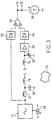
- FIG. 1 is a block diagram of a detector device according to the invention shown.
- the detector device is used for Locating an object 10.
- the detector device contains one Oscillator 12, which is connected to a transmitter coil 14.
- a receiving coil 16 is also provided.
- the transmitter coil 14 forms a primary side together with a capacitor 18 Resonant circuit.
- the receiving coil 16 forms together with one another adjustable capacitor 20 a secondary side Resonant circuit.
- the primary resonant circuit is an inductive one Throttle 22 connected to the oscillator 12.
- To create one Phase shift is the oscillator 12 with a frequency shifter 24 provided.
- the resonant circuit 16, 20 is connected to the input of an amplifier 26 connected.
- the output signal of amplifier 26 is called voltage U1 of the secondary side to an input of a summer 28 given.
- Voltage U2 of the primary side is given a voltage, which on a Point between the oscillator 12 and the inductive choke 22 is tapped.
- the output voltage of the summer 28 becomes amplified in a further amplifier 30 and a synchronous rectifier 32 fed.
- This synchronous rectifier 32 will switched by the voltage of the primary side U2.
- the tension of the The primary side U2 is the synchronous rectifier 32 via a delay element 48 fed.
- the output signal of the synchronous rectifier 32 becomes an analog-to-digital converter (ADC) 34, a data logger 36 and a display device 38.
- ADC analog-to-digital converter
- the device according to FIG. 1 works in the manner that the resonant circuit of the primary side 14, 18 through the oscillator 12 is excited. This excitation takes place via the inductive Throttle 22 which advantageously the oscillator 12 from decoupled from the resonant circuit. This creates particularly high Broadcast amplitudes, which lead to a strong alternating field and thus lead to an effective transmission of the search object 10.
- the transmission frequencies can vary depending on the application between about 500 Hz and 50 kHz can be selected. That from the transmitter coil 14 alternating field emitted generates in the object 10 Eddy currents, which is an electromagnetic one influenced by the object 10 Field. This is from the receiving coil 16 received, causing an oscillation in the secondary side Oscillating circuit 16, 20 is generated.
- This tension is amplified to an appropriate value by amplifier 26.
- the output voltage U1 of the amplifier 26 and a voltage U2, which between the oscillator 12 and the inductive choke 22nd is tapped, are fed to the summer 28.
- the two Voltages U1 and U2 are supplied to summer 28 in phase opposition, so that here both voltages are symmetrized Referring to the amount. In the general case this will however, full voltage compensation has not been achieved.
- the output voltage of the summer 28, which forms the measurement signal is fed to an amplifier 30 and reinforced there.
- the amplified output voltage of the Amplifier 30 is rectified in a synchronous rectifier 32.
- This synchronous rectifier 32 is powered by the voltage U2 of the primary side switched, so that another The measuring voltage is adjusted.
- the tension of the primary side U2 is the synchronous rectifier 32 via a delay element 48 fed.
- the output voltage of the synchronous rectifier 32 can then be displayed in an analog display device 38 to be brought. It can also use an ADC 34, for example be fed to a computer for digital data processing. It can also be entered into a data logger for registration become.
- FIG. 2 shows a further embodiment of an inventive one Detector device shown. Components that match those 1 correspond with the same reference numerals characterized. In contrast to the device according to FIG. 1 2 is a pure phase evaluation by a phase compensation device 40 instead. This can also compensate done electronically without a geometric or a spatial decoupling of the transmitter coil and the Receiving coil would be required.
- FIG. 3 shows a further embodiment of an inventive one Detector device shown. Components that match those from Fig. 1 or Fig. 2 are with the same reference numerals characterized. In contrast to the device 2 shows a pure DC voltage evaluation in FIG. 3 instead of.
- the signal voltages of the transmitter and the receiver by means of rectifiers 52 and 54 rectified.
- the output voltages of the rectifiers 52 and 54 are fed to a differential amplifier 56. In this meadow AC voltage compensation can be omitted.
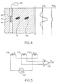
- FIG. 4 shows a possible application of a detector device according to the invention as a borehole probe.
- the borehole probe is as Tube 42 formed in which the primary side 44 and Secondary side 46 of the detector device are. additionally can advantageously be the sensing in the tube 42 Part of the electronics.
- This has advantages over borehole probes the state of the art. So far these have been slim cylindrical probes with small diameter used which a coil arrangement according to the coil arrangement shown in FIG. 5 of the prior art included.
- the three coils were made according to the prior art on a long iron core wound. It turned out to be disadvantageous that the arrangement not even a detection range with regard to a conventional bomb reached by 1 m. Furthermore, a such arrangement due to the long connecting cable damping Effects that led to adjustment errors.
- two voltage profiles also show that the measurement signal reaches a maximum value precisely when the search objects 10, 10a are in the middle of the probe. This enables the depth and location of the object to be specified precisely.
- the voltage labeled U 10 describes a voltage profile for the search object 10 in the close range.
- the voltage labeled U 10a describes a voltage profile for the search object 10a located in the far range.
Landscapes
- Physics & Mathematics (AREA)
- Engineering & Computer Science (AREA)
- Remote Sensing (AREA)
- Life Sciences & Earth Sciences (AREA)
- Electromagnetism (AREA)
- Environmental & Geological Engineering (AREA)
- Geology (AREA)
- General Life Sciences & Earth Sciences (AREA)
- General Physics & Mathematics (AREA)
- Geophysics (AREA)
- Geophysics And Detection Of Objects (AREA)
Applications Claiming Priority (2)
| Application Number | Priority Date | Filing Date | Title |
|---|---|---|---|
| DE2000145697 DE10045697A1 (de) | 2000-09-15 | 2000-09-15 | Verfahren zum Orten von Objekten und Detektorvorrichtung |
| DE10045697 | 2000-09-15 |
Publications (2)
| Publication Number | Publication Date |
|---|---|
| EP1189076A2 true EP1189076A2 (fr) | 2002-03-20 |
| EP1189076A3 EP1189076A3 (fr) | 2003-05-07 |
Family
ID=7656337
Family Applications (1)
| Application Number | Title | Priority Date | Filing Date |
|---|---|---|---|
| EP01116125A Withdrawn EP1189076A3 (fr) | 2000-09-15 | 2001-07-03 | Méthode de localisation d'objets et dispositif de détection |
Country Status (2)
| Country | Link |
|---|---|
| EP (1) | EP1189076A3 (fr) |
| DE (1) | DE10045697A1 (fr) |
Cited By (3)
| Publication number | Priority date | Publication date | Assignee | Title |
|---|---|---|---|---|
| EP1447685A3 (fr) * | 2003-02-12 | 2007-04-04 | Thermo Ramsey Corporation | Dispositif de contrôle du flux pour détecteurs de métaux |
| EP2653895A2 (fr) | 2012-04-17 | 2013-10-23 | Klaus Ebinger | Procédé de détection d'objets |
| WO2014041176A3 (fr) * | 2012-09-17 | 2014-06-26 | Paul Vahle Gmbh & Co. Kg | Système de détection de corps étrangers en métal pour des systèmes de transmission d'énergie inductive |
Families Citing this family (2)
| Publication number | Priority date | Publication date | Assignee | Title |
|---|---|---|---|---|
| DE10226286B3 (de) * | 2002-06-13 | 2004-01-22 | Sensorentechnologie Gettorf Gmbh | Einstichsensor |
| DE10342045A1 (de) * | 2003-09-11 | 2005-04-07 | Robert Bosch Gmbh | Vorrichtung zur Umfelderkennung |
Family Cites Families (6)
| Publication number | Priority date | Publication date | Assignee | Title |
|---|---|---|---|---|
| GB251429A (en) * | 1925-04-28 | 1926-05-06 | Elek Sk Malmletning Ab | Method and device for detecting and locating ores by electromagnetic means |
| EP0062396A3 (fr) * | 1981-03-26 | 1983-06-22 | Environmental Products Corporation | Détecteur de boítes à conserves d'aluminium |
| DE3421066A1 (de) * | 1984-06-06 | 1986-01-02 | Heimann Gmbh, 6200 Wiesbaden | Personenuntersuchungsgeraet |
| DE3840532A1 (de) * | 1988-12-01 | 1990-06-07 | Pepperl & Fuchs | Verfahren zur induktiven erzeugung eines elektrischen messsignals zur bestimmung des weges und/oder der position im raum und/oder von materialeigenschaften eines pruefkoerpers und nach diesem verfahren aufgebauter naeherungssensor und verwendung desselben als naeherherungsschalter |
| GB2230611B (en) * | 1989-03-30 | 1993-02-03 | Cintex Ltd | Product monitoring |
| GB8920412D0 (en) * | 1989-09-08 | 1989-10-25 | Ca Atomic Energy Ltd | Metal detecting system |
-
2000
- 2000-09-15 DE DE2000145697 patent/DE10045697A1/de not_active Withdrawn
-
2001
- 2001-07-03 EP EP01116125A patent/EP1189076A3/fr not_active Withdrawn
Cited By (5)
| Publication number | Priority date | Publication date | Assignee | Title |
|---|---|---|---|---|
| EP1447685A3 (fr) * | 2003-02-12 | 2007-04-04 | Thermo Ramsey Corporation | Dispositif de contrôle du flux pour détecteurs de métaux |
| EP2653895A2 (fr) | 2012-04-17 | 2013-10-23 | Klaus Ebinger | Procédé de détection d'objets |
| WO2014041176A3 (fr) * | 2012-09-17 | 2014-06-26 | Paul Vahle Gmbh & Co. Kg | Système de détection de corps étrangers en métal pour des systèmes de transmission d'énergie inductive |
| CN104781700A (zh) * | 2012-09-17 | 2015-07-15 | 保罗·瓦尔有限公司和两合公司 | 用于感应性能量传输系统的金属异物识别系统 |
| US20150276965A1 (en) * | 2012-09-17 | 2015-10-01 | Paul Vahle Gmbh & Co. Kg | Metal foreign object detection system for inductive power transmission systems |
Also Published As
| Publication number | Publication date |
|---|---|
| EP1189076A3 (fr) | 2003-05-07 |
| DE10045697A1 (de) | 2002-03-28 |
Similar Documents
| Publication | Publication Date | Title |
|---|---|---|
| DE3840532C2 (fr) | ||
| EP0945736B1 (fr) | Magnétomètre | |
| WO2010133501A1 (fr) | Capteur destiné à détecter des objets métalliques | |
| EP1797463B1 (fr) | Dispositif pour la localisation d'objets metalliques et procede d'ajustement dudit dispositif | |
| DE102005002238A1 (de) | Sensor zur Ortung metallischer Objekte sowie Messgerät mit einem solchen Sensor | |
| EP2633340A2 (fr) | Dispositif détecteur, en particulier détecteur de métaux comprenant un détecteur de champ magnétique à compensation de champ | |
| EP0049304B1 (fr) | Procédé de compensation d'erreurs dues à la température dans des circuits de mesure à courant alternatif, en particulier dans des appareils de mesure de distance, et dispositif pour réaliser cette méthode | |
| DE102016217255A1 (de) | Drehwinkelsensor und Statorelement für diesen | |
| EP1797464B1 (fr) | Détecteur pour la localisation d'objets métalliques | |
| EP1853941B1 (fr) | Procede de detection d'objets renfermes dans un milieu et dispositif de mesure destine a la mise en oeuvre de ce procede | |
| DE4339419C2 (de) | Einrichtungen und Verfahren zum Erkennen von Metallgegenständen | |
| EP1869505B1 (fr) | Procede pour localiser des objets enfermes dans un milieu et appareil de mesure pour la mise en oeuvre dudit procede | |
| DE2644928B2 (de) | Elektromagnetischer Fahrzeugdetektor | |
| EP1189076A2 (fr) | Méthode de localisation d'objets et dispositif de détection | |
| DE3615291A1 (de) | Elektromagnetischer wandler sowie einrichtung zur bestimmung einer relativgeschwindigkeit und/oder einer form unter verwendung eines derartigen wandlers | |
| EP3314310B1 (fr) | Dispositif et procédé de détection d'un objet | |
| EP0024307B1 (fr) | Dispositif pour la compensation du champ magnétique parasite d'un objet à l'aide d'une installation d'auto-protection magnétique | |
| EP0152904A2 (fr) | Méthode et dispositif pour le test, et/ou la mesure d'objets électriquement conducteurs devant être testés | |
| DE3518161C2 (fr) | ||
| DE922081C (de) | Verfahren und Anordnung zur Messung von Azimut und Entfernung eines Gegenstandes beiGeraeten zur Auffindung von Gegenstaenden mit Hilfe von elektromagnetischen Wellen | |
| DE19858713C2 (de) | Verfahren und Vorrichtung zum Nachweis von im Boden befindlichen Metallobjekten | |
| EP0780705A2 (fr) | Procédé de recherche et agencement des sondes pour localiser des objets souterrains | |
| EP1059542A2 (fr) | Procédé et dispositif de détection des corps métalliques sur une bande en mouvement | |
| EP1324077B1 (fr) | Procédé et dispositif de détection des objets métalliques | |
| EP0731929B1 (fr) | Procede et dispositif permettant de detecter un objet electroconducteur |
Legal Events
| Date | Code | Title | Description |
|---|---|---|---|
| PUAI | Public reference made under article 153(3) epc to a published international application that has entered the european phase |
Free format text: ORIGINAL CODE: 0009012 |
|
| AK | Designated contracting states |
Kind code of ref document: A2 Designated state(s): AT BE CH CY DE DK ES FI FR GB GR IE IT LI LU MC NL PT SE TR |
|
| AX | Request for extension of the european patent |
Free format text: AL;LT;LV;MK;RO;SI |
|
| PUAL | Search report despatched |
Free format text: ORIGINAL CODE: 0009013 |
|
| AK | Designated contracting states |
Designated state(s): AT BE CH CY DE DK ES FI FR GB GR IE IT LI LU MC NL PT SE TR |
|
| AX | Request for extension of the european patent |
Extension state: AL LT LV MK RO SI |
|
| 17P | Request for examination filed |
Effective date: 20031104 |
|
| AKX | Designation fees paid |
Designated state(s): AT BE CH CY DE DK ES FI FR GB GR IE IT LI LU MC NL PT SE TR |
|
| 17Q | First examination report despatched |
Effective date: 20080904 |
|
| STAA | Information on the status of an ep patent application or granted ep patent |
Free format text: STATUS: THE APPLICATION HAS BEEN WITHDRAWN |
|
| 18W | Application withdrawn |
Effective date: 20090219 |