EP1189122A2 - Méthode et appareil pour calculer une valeur de correction pour le déplacement thermique dans une machine outil - Google Patents
Méthode et appareil pour calculer une valeur de correction pour le déplacement thermique dans une machine outil Download PDFInfo
- Publication number
- EP1189122A2 EP1189122A2 EP01121650A EP01121650A EP1189122A2 EP 1189122 A2 EP1189122 A2 EP 1189122A2 EP 01121650 A EP01121650 A EP 01121650A EP 01121650 A EP01121650 A EP 01121650A EP 1189122 A2 EP1189122 A2 EP 1189122A2
- Authority
- EP
- European Patent Office
- Prior art keywords
- amount
- main spindle
- displacement amount
- displacement
- correction value
- Prior art date
- Legal status (The legal status is an assumption and is not a legal conclusion. Google has not performed a legal analysis and makes no representation as to the accuracy of the status listed.)
- Withdrawn
Links
Images


Classifications
-
- B—PERFORMING OPERATIONS; TRANSPORTING
- B23—MACHINE TOOLS; METAL-WORKING NOT OTHERWISE PROVIDED FOR
- B23Q—DETAILS, COMPONENTS, OR ACCESSORIES FOR MACHINE TOOLS, e.g. ARRANGEMENTS FOR COPYING OR CONTROLLING; MACHINE TOOLS IN GENERAL CHARACTERISED BY THE CONSTRUCTION OF PARTICULAR DETAILS OR COMPONENTS; COMBINATIONS OR ASSOCIATIONS OF METAL-WORKING MACHINES, NOT DIRECTED TO A PARTICULAR RESULT
- B23Q15/00—Automatic control or regulation of feed movement, cutting velocity or position of tool or work
- B23Q15/007—Automatic control or regulation of feed movement, cutting velocity or position of tool or work while the tool acts upon the workpiece
- B23Q15/18—Compensation of tool-deflection due to temperature or force
-
- G—PHYSICS
- G05—CONTROLLING; REGULATING
- G05B—CONTROL OR REGULATING SYSTEMS IN GENERAL; FUNCTIONAL ELEMENTS OF SUCH SYSTEMS; MONITORING OR TESTING ARRANGEMENTS FOR SUCH SYSTEMS OR ELEMENTS
- G05B19/00—Program-control systems
- G05B19/02—Program-control systems electric
- G05B19/18—Numerical control [NC], i.e. automatically operating machines, in particular machine tools, e.g. in a manufacturing environment, so as to execute positioning, movement or co-ordinated operations by means of program data in numerical form
- G05B19/404—Numerical control [NC], i.e. automatically operating machines, in particular machine tools, e.g. in a manufacturing environment, so as to execute positioning, movement or co-ordinated operations by means of program data in numerical form characterised by control arrangements for compensation, e.g. for backlash, overshoot, tool offset, tool wear, temperature, machine construction errors, load, inertia
-
- G—PHYSICS
- G05—CONTROLLING; REGULATING
- G05B—CONTROL OR REGULATING SYSTEMS IN GENERAL; FUNCTIONAL ELEMENTS OF SUCH SYSTEMS; MONITORING OR TESTING ARRANGEMENTS FOR SUCH SYSTEMS OR ELEMENTS
- G05B2219/00—Program-control systems
- G05B2219/30—Nc systems
- G05B2219/49—Nc machine tool, till multiple
- G05B2219/49205—Compensate with stored values as function of machining time
-
- G—PHYSICS
- G05—CONTROLLING; REGULATING
- G05B—CONTROL OR REGULATING SYSTEMS IN GENERAL; FUNCTIONAL ELEMENTS OF SUCH SYSTEMS; MONITORING OR TESTING ARRANGEMENTS FOR SUCH SYSTEMS OR ELEMENTS
- G05B2219/00—Program-control systems
- G05B2219/30—Nc systems
- G05B2219/49—Nc machine tool, till multiple
- G05B2219/49206—Compensation temperature, thermal displacement, use measured temperature
-
- G—PHYSICS
- G05—CONTROLLING; REGULATING
- G05B—CONTROL OR REGULATING SYSTEMS IN GENERAL; FUNCTIONAL ELEMENTS OF SUCH SYSTEMS; MONITORING OR TESTING ARRANGEMENTS FOR SUCH SYSTEMS OR ELEMENTS
- G05B2219/00—Program-control systems
- G05B2219/30—Nc systems
- G05B2219/49—Nc machine tool, till multiple
- G05B2219/49209—Compensation by using temperature feelers on slide, base, workhead
-
- G—PHYSICS
- G05—CONTROLLING; REGULATING
- G05B—CONTROL OR REGULATING SYSTEMS IN GENERAL; FUNCTIONAL ELEMENTS OF SUCH SYSTEMS; MONITORING OR TESTING ARRANGEMENTS FOR SUCH SYSTEMS OR ELEMENTS
- G05B2219/00—Program-control systems
- G05B2219/30—Nc systems
- G05B2219/49—Nc machine tool, till multiple
- G05B2219/49219—Compensation temperature, thermal displacement
Definitions
- the present invention 'relates to a method and apparatus for calculating correction values for thermal displacement occurring along an axis of a main spindle in a machine tool.
- a machine tool has sources of the heat generation at respective portions, and from these sources of the heat generation, heat is transmitted and causes the respective portions of the machine tool to thermally deform.
- the bearing rotatably holding the main spindle generates heat due to rolling of a rolling element, and the main spindle expands, and this causes machining errors.
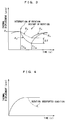
- Fig. 4 shows the condition where the main spindle thermally displaces (expands) with time after the main spindle is rotated. As shown in the figure, after the rotation is started, the main spindle expands at a predetermined time constant, and then turns into a steady state soon thereafter.
- a liquid coolant is supplied and circulated in a housing that holds the main spindle to cool the bearing, and in addition, the temperature in the vicinity of the main spindle is measured, the amount of thermal displacement of the main spindle is estimated on the basis of the measured temperature, and a correction value is calculated on the basis of the estimated thermal displacement amount, and tool offset is made on the basis of the calculated correction value, whereby the thermal displacement is canceled.
- the main spindle In a running condition where the main power supply of the machine tool is turned on, the main spindle is not always rotated, but occasionally stopped. For example, in the case of a machining center, when a tool that has reached the wearing limit is replaced with a new one, the rotation of the main spindle must be interrupted in order to set a tool offset value of the replaced tool. Also, in a case where a workpiece after being machined is measured on the machine tool, the rotation of the main spindle must be interrupted. When the rotation is interrupted, the main spindle is cooled, and as shown by the chain double-dashed line in Fig. 4, the amount of thermal displacement decreases, that is, the main spindle contracts.
- the cooling condition in the vicinity of the main spindle to be measured that is, the cooling condition in the vicinity of the bearing does not always agree with the cooling condition of the main spindle itself, so that a phenomenon in which the main spindle is cooled later occurs. Therefore, the actual contraction amount of the main spindle is smaller than the contraction amount estimated on the basis of the measured temperature in the vicinity of the main spindle. In other words, the actual contraction of the main spindle is delayed from the estimated contraction on the basis of the measured temperature in the vicinity of the main spindle.
- Fig. 5 the actual contraction condition of the main spindle is shown by the chain double-dashed line, and the estimated contraction condition on the basis of the measured temperature in the vicinity of the main spindle is shown by the continuous line.
- the actual contraction amount of the main spindle has a delay amount ⁇ Z to the contraction amount estimated on the basis of the measured temperature in the vicinity of the main spindle, and thereafter, with the elapse of time, the main spindle temperature and the temperature in the vicinity of the main spindle reach the same temperature, and the abovementioned delay amount converges at zero.
- the actual contraction amount of the main spindle is delayed by ⁇ Z to the estimated contraction amount on the basis of the measured temperature in the vicinity of the main spindle. Therefore, when the correction value is calculated on the basis of the estimated contraction amount, an error corresponding to the delay amount ⁇ Z to the actual contraction amount of the main spindle occurs, so that accurate correction cannot be made.
- the invention is made in view of the abovementioned circumstances, and the object thereof is to provide a method and apparatus for calculating a correction value for thermal displacement in a machine tool whereby accurate correction values can be calculated when the rotation of the main spindle is interrupted or the rotation of the main spindle is restarted.
- the present invention relates to a method for calculating a correction value for thermal displacement occurring along an axis of a main spindle in a machine tool, the method comprising the steps of:
- the amount of thermal displacement occurring along the axis of the main spindle on the basis of the measured temperature in the vicinity of the main spindle is estimated.
- a correction value is calculated on the basis of the estimated thermal displacement amount alone, and on the other hand, when the rotation of the main spindle is restarted after interruption thereof, the amount of displacement delay occurring due to the interruption is estimated, and a correction value is calculated on the basis of the estimated displacement delay amount and the estimated thermal displacement amount.
- a correction value on the basis of the displacement delay amount and the estimated thermal displacement amount can be carried out by the following, that is, an adjusting displacement amount is calculated on the basis of the estimated displacement delay amount, and the correction value is calculated on the basis of a displacement amount obtained by addition or subtraction of the adjusting displacement amount to/from the estimated thermal displacement amount.
- this amount can be calculated from the following expression.
- ⁇ c ⁇ Z ⁇ exp(-t c /T c )
- ⁇ Z is the displacement delay amount ( ⁇ m) at the restart of the rotation of the main spindle
- T c is a time constant
- t c is a time (s) elapsed from the restart of the rotation of the main spindle.
- the displacement amount obtained by addition or subtraction of the adjusting displacement amount calculated from such a calculation expression to/from the estimated thermal displacement amount is approximate to the actual displacement amount of the main spindle. Therefore, by calculating a correction value on the basis of this displacement amount, a more accurate correction can be made.
- the abovementioned method for calculating the correction value can be preferably carried out by the following apparatus. That is, the apparatus for calculating a correction value for thermal displacement occurring along an axis of a main spindle in a machine tool, the apparatus comprising:
- the adjusting displacement amount calculating means can be constructed so as to calculate the adjusting displacement amount ⁇ c from the following expression.
- ⁇ c ⁇ Z ⁇ exp(-t c /T c )
- ⁇ Z is the displacement delay amount ( ⁇ m) at the restart of the rotation of the main spindle
- T c is a time constant
- t c is a time (s) elapsed from the restart of the rotation of the main spindle.
- an amount of displacement occurring along the axis of the main spindle during the interruption is estimated on the basis of an amount of the thermal displacement estimated on the basis of a temperature measured immediately before the interruption and a predetermined delay amount to the estimated thermal displacement amount, and the correction value can be calculated on the basis of the estimated displacement amount.
- an amount of displacement occurring along the axis of the main spindle during the interruption is estimated on the basis of an amount of the thermal displacement estimated on the basis of a temperature measured immediately before the interruption and a predetermined delay amount to the estimated thermal displacement amount, that is, a displacement amount approximate to the actual displacement amount of the main spindle during the interruption is estimated, and the correction value during the interruption is calculated on the basis of this estimated displacement amount. Therefore, a more accurate correction can be made for thermal displacement of the main spindle during the interruption of the rotation. Thereby, setting of a tool offset value after replacing the tool or workpiece measurements on the machine tool during the interruption can be made with high accuracy.
- the method of the invention can be preferably carried out by the following apparatus. That is, the apparatus is constructed so that, when the rotation of the main spindle is interrupted, the correction value calculating means estimates an amount of displacement occurring along the axis of the main spindle during the interruption on the basis of an amount of the thermal displacement estimated on the basis of a temperature measured immediately before the interruption and a predetermined delay amount to the estimated thermal displacement amount, and calculates the correction value on the basis of the estimated displacement amount.
- the amount ⁇ B of the displacement occurring along the axis of the main spindle during the interruption can be calculated from the following expression.
- ⁇ B ⁇ A1 ⁇ exp(-t B /T B )
- ⁇ A1 is the estimated thermal displacement amount immediately before the interruption of the rotation of the main spindle
- T B is a time constant
- t B is a elapsed time from interruption of the rotation of the main spindle.
- FIG. 1 is a block diagram showing the schematic construction of a apparatus for calculating a correction value relating to the present embodiment.
- the apparatus 1 for calculating the correction value of the present embodiment comprises a temperature sensor 2 provided at the lower end of a main spindle head 14 comprising a machine tool 11, a temperature detecting section 3 for detecting the temperature at the lower end of the main spindle head 14 by receiving a detection signal from this temperature sensor 2, and correction value calculation section 4 which receives temperature data detected by the temperature detecting section 3, calculates an amount of the thermal displacement of the main spindle 15 and a correction value in accordance with this amount of the thermal displacement, and transmits the calculated correction value to a NC device 17.
- 12 denotes a bed
- 13 denotes a column
- 16 denotes a table.
- a contact type sensor comprising a thermistor, bimetal, thermocouple and the like, and a non-contact type sensor using thermal radiation can be used.
- the temperature detecting section 3 samples detection signals transmitted from the temperature sensor 2 at every prescribed'time to prepare temperature data, and transmits the prepared temperature data to the correction value calculation section 4, successively.
- the correction value calculation section 4 comprises thermal displacement amount estimating section 5, adjusting displacement amount calculating section 6, correction value calculating section 7 and rotation condition storing section 8.
- the thermal displacement amount estimating section 5 receives temperature data successively transmitted from the temperature detecting section 3, calculates the amount of the thermal displacement of the main spindle 15 on the basis of the received temperature data and a predetermined thermal displacement amount calculation expression, and successively transmits the calculated thermal displacement data to the adjusting displacement amount calculating section 6 and correction value calculating section 7.
- the thermal displacement amount calculation expression is a calculation expression that is experientially set based on the relationship between the temperature data, which is obtained by measuring the temperature at the lower end of the main spindle head 14 by the temperature sensor 2 and temperature detecting section 3 upon rotating the main spindle 15, and displacement data, which is obtained by measuring the displacement of the main spindle 15 in accordance with the temperature by using a displacement meter, and for example, the following thermal displacement amount calculation expression can be obtained.
- ⁇ A ⁇ ⁇ ⁇ K t + ⁇
- ⁇ A is the thermal displacement amount
- ⁇ is a coefficient
- ⁇ K t is the rise of temperature to the predetermined reference temperature at the time t
- ⁇ is a constant (correction term).
- the rotation condition storing section 8 receives the rotation condition of the main spindle 15 from the NC device 17, and stores the period of rotation and period of interruption of the main spindle 15 in time series.
- the adjusting displacement amount calculating section 6 executes processing for estimating a difference between the actual displacement amount of the main spindle 15 after the interruption of the rotation of the main spindle 15 and the displacement amount estimated by the thermal displacement amount estimating section 5, that is, an amount of displacement delay.
- the displacement expression after the interruption of the rotation is experientially set based on the obtained displacement data.
- the displacement expression thus set is, for example, as follows (see Fig. 3).
- ⁇ B ⁇ A1 ⁇ exp (-t B /T B )
- ⁇ B is the displacement amount
- ⁇ A1 is the estimated thermal displacement amount immediately before the interruption of the rotation, which has been calculated by the thermal displacement amount estimating section 5.
- t B is a time elapsed from the interruption of the rotation
- T B is a time constant.
- the adjusting displacement amount calculating section 6 receives a rotation stop signal from the NC device 17, and calculates an amount ⁇ Z tB of displacement delay on the basis of the estimated thermal displacement amount ⁇ A transmitted from the thermal displacement amount estimating section 5 and the above predetermined expression. This calculation can be expressed from the following operation expression.
- the adjusting displacement amount calculating section 6 receives a rotation signal from the NC device 17, and on the basis of the amount ⁇ Z tB of displacement delay (referred to as ⁇ Z) immediately before the restart of the rotation that has been calculated as mentioned above, executes processing for calculating an adjusting displacement amount ⁇ c , and transmits the calculated adjusting displacement amount ⁇ c data to the correction value calculating section 7.
- ⁇ c ⁇ Z ⁇ exp(-t c /T c ) t c is a time elapsed from the restart of the rotation of the main spindle 15, and T c is a time constant.
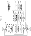
- the correction value calculating section 7 receives a signal regarding the rotation condition of the main spindle 15 from the NC device 17, receives data from the thermal displacement amount estimating section 5, adjusting displacement amount calculating section 6, and rotation condition storing section 8, calculates a correction value by executing the processing shown in Fig. 2, and transmits the calculated correction value data to the NC device 17.
- the correction value calculating section 7 receives data regarding the rotation condition of the main spindle 15 from the NC device 17 first (step S1), judges the rotation condition of the main spindle 15 (step S2), and when the main spindle 15 is rotated, receives data from the rotation condition storing section 8, judges whether or not the main spindle 15 was in a rotating condition previous to this, that is, judges whether or not the rotation of the main spindle 15 is the initial rotation (start-up rotation) (step S3), and in the case of the start-up rotation, executes the processings of step S4 onward, and in the case of the restart of the rotation, executes the processings of step S8 onward.
- start-up rotation start-up rotation
- step S4 the correction value calculating section 7 receives the estimated thermal displacement amount ⁇ A from the thermal displacement amount estimating section 5, calculates a correction value for canceling such displacement on the basis of the received estimated thermal displacement amount ⁇ A (step S5), and transmits the calculated correction value to the NC device 17 (step S6).
- the correction value is in the direction in which the main spindle 15 is separated from the workpiece, that is, positive, so that the estimated thermal displacement amount ⁇ A and the correction value becomes equal to each other. Thereafter, until the rotation of the main spindle 15 is interrupted, the processings of step S4 through S7 are repeatedly executed (step S7).
- the abovementioned ⁇ K tC is the temperature data at the same time as t c .
- the correction displacement amount ⁇ D and correction value becomes equal to each other.
- step S12 the processings of step S8 through S12 are repeatedly executed in order (step S12).
- the correction displacement amount ⁇ D that can be obtained by repeatedly executing the processings of step S8 through S12 is expressed by a curve after the restart of the rotation as shown by the dashed line in Fig. 3.
- the actual displacement curve (the chain double-dashed line) of the main spindle 15 after the restart of the rotation and the curve (the dashed line) of the correction displacement amount ⁇ D are drawn so as not to overlap each other, however, by properly setting the time constant T c , the curve showing the correction displacement amount ⁇ D can be approximated to the curve of the actual displacement curve.
- steps S7 and S12 when it is judged that the rotation of the main spindle 15 has been interrupted, the process progresses to step S17, and when the operation of the machine tool 11 has been finished, the processing is ended, and when the operation of the machine tool 11 has been continued, the processings of step S1 and onward are repeated.
- step S2 in the case where it is judged that the rotation of the main spindle 15 is being interrupted, data is received from the rotation condition storing section 8, and it is judged whether or not main spindle 15 previous to this was in a rotating condition, that is, whether or not the rotation of the main spindle 15 was interrupted after the main spindle 15 was rotated (step S13), and in the case where the rotation of the main spindle 15 was interrupted after the main spindle 15 was rotated, the process progresses to step S14, and when the rotation of the main spindle 15 was not interrupted after the main spindle 15 was rotated, that is, the main spindle 15 was never rotated after start-up thereof, the process progresses to step S17.
- step S14 data of ⁇ B calculated by the adjusting displacement amount calculating section 6 is read-in, a correction value for canceling thermal displacement of the main spindle 15 during the interruption is calculated on the basis of this ⁇ B' (step S15), and the obtained correction value is transmitted to the NC device 17 (step S16).
- ⁇ B is obtained from an expression that has been experientially lead out as mentioned above, and ⁇ B (displacement amount) calculated from such an calculation expression is approximate to the actual displacement amount of the main spindle 15 that has interrupted the rotation. Therefore, by using this ⁇ B (displacement amount), a more accurate correction value can be calculated for thermal displacement of the main spindle 15 during the interruption of the rotation. Thereby, setting of a tool offset value after replacing the tool or workpiece measurements on the machine tool that are carried out during the interruption of the rotation of the main spindle 15 can be carried out with high accuracy.
- a correction value is calculated on the basis of the the estimated thermal displacement amount ⁇ A that has been estimated by the thermal displacement amount estimating section 5 alone, and on the other hand, when the rotation of the main spindle 15 is restarted after interruption thereof, an amount ⁇ Z tB of displacement delay occurring due to the interruption of the rotation of the main spindle 15 is estimated, and an adjusting displacement amount ⁇ c is calculated on the basis of the estimated displacement delay amount ⁇ Z tB , the correction value is calculated on the basis of a correction displacement amount ⁇ D obtained by addition of the calculated adjusting displacement amount ⁇ c to the estimated thermal displacement amount ⁇ A .
- the correction value calculation section 4 is provided in a separate manner from the NC device 17, however, the construction of these are not limited, and the correction value calculation section 4 may be installed inside the NC device 17.
- one temperature sensor 2 is provided, however, the construction is not limited to this, and needless to say, a plurality of temperature sensors 2 may be provided.
- the abovementioned ⁇ A is calculated from a calculation expression that is set in accordance with this construction.
- an estimated displacement amount ⁇ A after the interruption of the rotation of the main spindle 15 is calculated on the basis of the measured temperature
- the construction is not limited to this, the estimated displacement amount ⁇ A may be calculated from a properly set approximate expression.
Landscapes
- Engineering & Computer Science (AREA)
- Mechanical Engineering (AREA)
- Human Computer Interaction (AREA)
- Manufacturing & Machinery (AREA)
- Physics & Mathematics (AREA)
- General Physics & Mathematics (AREA)
- Automation & Control Theory (AREA)
- Automatic Control Of Machine Tools (AREA)
- Machine Tool Sensing Apparatuses (AREA)
- Numerical Control (AREA)
Applications Claiming Priority (2)
| Application Number | Priority Date | Filing Date | Title |
|---|---|---|---|
| JP2000278426 | 2000-09-13 | ||
| JP2000278426A JP2002086329A (ja) | 2000-09-13 | 2000-09-13 | 工作機械の熱変位補正量算出方法及び熱変位補正量算出装置 |
Publications (2)
| Publication Number | Publication Date |
|---|---|
| EP1189122A2 true EP1189122A2 (fr) | 2002-03-20 |
| EP1189122A3 EP1189122A3 (fr) | 2006-08-09 |
Family
ID=18763594
Family Applications (1)
| Application Number | Title | Priority Date | Filing Date |
|---|---|---|---|
| EP01121650A Withdrawn EP1189122A3 (fr) | 2000-09-13 | 2001-09-13 | Méthode et appareil pour calculer une valeur de correction pour le déplacement thermique dans une machine outil |
Country Status (3)
| Country | Link |
|---|---|
| US (1) | US6651019B2 (fr) |
| EP (1) | EP1189122A3 (fr) |
| JP (1) | JP2002086329A (fr) |
Cited By (4)
| Publication number | Priority date | Publication date | Assignee | Title |
|---|---|---|---|---|
| US5449457A (en) * | 1991-04-22 | 1995-09-12 | Hoechst Celanese Corporation | Liquid membrane modules with minimal effective membrane thickness and methods of making the same |
| CN102346026A (zh) * | 2010-08-02 | 2012-02-08 | 株式会社三丰 | 工业用机械 |
| CN103240640A (zh) * | 2012-02-13 | 2013-08-14 | 发那科株式会社 | 机床的暖机运转控制装置 |
| CN109613886A (zh) * | 2017-10-04 | 2019-04-12 | 发那科株式会社 | 热位移校正系统 |
Families Citing this family (25)
| Publication number | Priority date | Publication date | Assignee | Title |
|---|---|---|---|---|
| JP4299761B2 (ja) * | 2004-10-22 | 2009-07-22 | ヤマザキマザック株式会社 | 工作機械の熱変位補正方法及び熱変位補正装置 |
| JP4891104B2 (ja) * | 2007-01-29 | 2012-03-07 | オークマ株式会社 | 工作機械の熱変位推定方法 |
| JP4955451B2 (ja) * | 2007-05-16 | 2012-06-20 | ヤマザキマザック株式会社 | 複合旋盤装置の制御方法、複合旋盤装置、刃先位置登録装置、及び刃先位置検出装置 |
| JP4959508B2 (ja) * | 2007-11-05 | 2012-06-27 | 三菱重工業株式会社 | 工作機械のワーク加工方法及び挙動計測装置 |
| JP4959641B2 (ja) * | 2008-07-14 | 2012-06-27 | 株式会社東芝 | 情報記憶装置 |
| TW201021959A (en) * | 2008-12-11 | 2010-06-16 | Ind Tech Res Inst | A thermal error compensation method for machine tools |
| JP4917665B1 (ja) * | 2010-11-11 | 2012-04-18 | ファナック株式会社 | 工作機械の熱変位補正方法及び熱変位補正装置 |
| JP5568005B2 (ja) * | 2010-12-28 | 2014-08-06 | オークマ株式会社 | 工作機械の熱変位補正装置及び方法 |
| JP5490304B2 (ja) * | 2011-02-24 | 2014-05-14 | 三菱電機株式会社 | 放電加工装置および放電加工システム |
| JP5502912B2 (ja) * | 2012-01-19 | 2014-05-28 | ファナック株式会社 | 工作機械の熱変位補正装置 |
| CN103544368A (zh) * | 2012-07-18 | 2014-01-29 | 中国石油化工股份有限公司 | 微观驱油实验波驱贡献比计算方法 |
| RU2538884C1 (ru) * | 2013-05-23 | 2015-01-10 | Федеральное государственное бюджетное образовательное учреждение высшего профессионального образования "Московский государственный технологический университет "СТАНКИН" (ФГБОУ ВПО МГТУ "СТАНКИН") | Способ компенсации тепловых деформаций исполнительных узлов металлорежущего станка с чпу |
| JP5698798B2 (ja) * | 2013-06-24 | 2015-04-08 | ファナック株式会社 | 熱変位量補正機能を有する工作機械 |
| KR102128632B1 (ko) * | 2014-11-03 | 2020-06-30 | 두산공작기계 주식회사 | 공작기계의 열변위 보정 방법 및 장치 |
| RU2573854C1 (ru) * | 2014-11-18 | 2016-01-27 | Федеральное государственное бюджетное образовательное учреждение высшего профессионального образования "Московский государственный технологический университет "СТАНКИН" (ФГБОУ ВПО МГТУ "СТАНКИН") | Способ компенсации тепловых деформаций металлорежущих станков с чпу |
| JP6042917B2 (ja) * | 2015-01-30 | 2016-12-14 | ファナック株式会社 | 工作機械の熱変位補正装置 |
| JP2017024108A (ja) | 2015-07-21 | 2017-02-02 | ファナック株式会社 | 工作機械の熱変位補正装置 |
| JP6877989B2 (ja) * | 2016-12-22 | 2021-05-26 | オークマ株式会社 | 工作機械の温度推定方法及び熱変位補正方法 |
| RU2636209C1 (ru) * | 2017-01-12 | 2017-11-21 | Федеральное государственное бюджетное образовательное учреждение высшего образования "Московский государственный технологический университет "СТАНКИН" (ФГБОУ ВО "МГТУ "СТАНКИН") | Способ управления охлаждением высокоскоростного мотор-шпинделя металлорежущего станка |
| JP6564412B2 (ja) * | 2017-03-21 | 2019-08-21 | ファナック株式会社 | 機械学習装置及び熱変位補正装置 |
| JP6683667B2 (ja) | 2017-10-04 | 2020-04-22 | ファナック株式会社 | 熱変位補正システム |
| JP6673950B2 (ja) * | 2018-01-31 | 2020-04-01 | ファナック株式会社 | 基準温度設定装置、基準温度設定方法及び基準温度設定プログラム |
| US11467066B2 (en) * | 2019-01-31 | 2022-10-11 | Dalian University Of Technology | Method for determining the preload value of the screw based on thermal error and temperature rise weighting |
| JP7290508B2 (ja) * | 2019-08-07 | 2023-06-13 | ファナック株式会社 | 工作機械システム |
| JP7303065B2 (ja) * | 2019-08-23 | 2023-07-04 | ファナック株式会社 | 機械学習装置、制御システム及び機械学習方法 |
Family Cites Families (6)
| Publication number | Priority date | Publication date | Assignee | Title |
|---|---|---|---|---|
| JPS6114835A (ja) * | 1984-06-28 | 1986-01-23 | Yamazaki Mazak Corp | 数値制御工作機械における熱寸法変位の補正制御方法 |
| JP3136464B2 (ja) * | 1995-09-22 | 2001-02-19 | オークマ株式会社 | 工作機械の熱変位補正方法 |
| JP3151655B2 (ja) * | 1996-02-19 | 2001-04-03 | オークマ株式会社 | 工作機械の熱変位推定方法 |
| JP3389417B2 (ja) * | 1996-05-29 | 2003-03-24 | 大阪機工株式会社 | ロストモーションの補正方法 |
| JP3154946B2 (ja) * | 1996-11-11 | 2001-04-09 | ファナック株式会社 | 工作機械の熱変位補正方法 |
| US6000889A (en) * | 1997-08-06 | 1999-12-14 | Brother Kogyo Kabushiki Kaisha | Thermal change computation apparatus for machine tool and storage medium for executing the computation |
-
2000
- 2000-09-13 JP JP2000278426A patent/JP2002086329A/ja active Pending
-
2001
- 2001-09-12 US US09/949,834 patent/US6651019B2/en not_active Expired - Fee Related
- 2001-09-13 EP EP01121650A patent/EP1189122A3/fr not_active Withdrawn
Cited By (6)
| Publication number | Priority date | Publication date | Assignee | Title |
|---|---|---|---|---|
| US5449457A (en) * | 1991-04-22 | 1995-09-12 | Hoechst Celanese Corporation | Liquid membrane modules with minimal effective membrane thickness and methods of making the same |
| CN102346026A (zh) * | 2010-08-02 | 2012-02-08 | 株式会社三丰 | 工业用机械 |
| CN103240640A (zh) * | 2012-02-13 | 2013-08-14 | 发那科株式会社 | 机床的暖机运转控制装置 |
| CN103240640B (zh) * | 2012-02-13 | 2014-12-10 | 发那科株式会社 | 机床的暖机运转控制装置 |
| CN109613886A (zh) * | 2017-10-04 | 2019-04-12 | 发那科株式会社 | 热位移校正系统 |
| US11305395B2 (en) | 2017-10-04 | 2022-04-19 | Fanuc Corporation | Thermal displacement compensation system |
Also Published As
| Publication number | Publication date |
|---|---|
| US20020038189A1 (en) | 2002-03-28 |
| EP1189122A3 (fr) | 2006-08-09 |
| US6651019B2 (en) | 2003-11-18 |
| JP2002086329A (ja) | 2002-03-26 |
Similar Documents
| Publication | Publication Date | Title |
|---|---|---|
| US6651019B2 (en) | Method and apparatus for calculating correction value for thermal displacement in machine tool | |
| US10496072B2 (en) | Displacement estimation method and thermal displacement correction method for machine tool | |
| US7778725B2 (en) | Method for estimating thermal displacement in machine tool | |
| Krulewich | Temperature integration model and measurement point selection for thermally induced machine tool errors | |
| JP3136464B2 (ja) | 工作機械の熱変位補正方法 | |
| US10245697B2 (en) | Method for controlling temperature adjustment system of machine | |
| CN106371404A (zh) | 机床的热位移校正装置 | |
| JP3151655B2 (ja) | 工作機械の熱変位推定方法 | |
| JP2009061565A (ja) | 加工方法 | |
| JP7191585B2 (ja) | 工作機械のスピンドルと共に幾何的プローブを使用する方法およびかかる方法を実施するように構成された工作機械 | |
| CN111451836B (zh) | 机床的热位移校正方法以及热位移校正装置 | |
| JP4245375B2 (ja) | 工作機械の制御方法及び工作機械 | |
| JP6561003B2 (ja) | 工作機械の熱変位補正方法、工作機械 | |
| JP3422462B2 (ja) | 工作機械の熱変位推定方法 | |
| JP2004148443A (ja) | 工具の熱変位補正方法 | |
| JP2004195594A (ja) | 工作機械の加工方法 | |
| TWI276505B (en) | Grinding device and grinding method | |
| JPH0847842A (ja) | 工作機械及び工作方法 | |
| JP2004249402A (ja) | 工作機械の高精度加工方法 | |
| JP2003057990A (ja) | 定着装置の温度制御装置 | |
| JP3805932B2 (ja) | 工作機械の熱変位推定方法 | |
| JP3495255B2 (ja) | 工作機械の熱変位推定方法 | |
| US20240077115A1 (en) | Temperature rise value estimating method, thermal displacement amount estimating method, and bearing cooling apparatus control method for machine tool, and machine tool | |
| JP2588836Y2 (ja) | 研削盤のワーク寸法制御装置 | |
| JP2001269840A (ja) | 工作機械の熱変位推定方法 |
Legal Events
| Date | Code | Title | Description |
|---|---|---|---|
| PUAI | Public reference made under article 153(3) epc to a published international application that has entered the european phase |
Free format text: ORIGINAL CODE: 0009012 |
|
| AK | Designated contracting states |
Kind code of ref document: A2 Designated state(s): AT BE CH CY DE DK ES FI FR GB GR IE IT LI LU MC NL PT SE TR |
|
| AX | Request for extension of the european patent |
Free format text: AL;LT;LV;MK;RO;SI |
|
| PUAL | Search report despatched |
Free format text: ORIGINAL CODE: 0009013 |
|
| AK | Designated contracting states |
Kind code of ref document: A3 Designated state(s): AT BE CH CY DE DK ES FI FR GB GR IE IT LI LU MC NL PT SE TR |
|
| AX | Request for extension of the european patent |
Extension state: AL LT LV MK RO SI |
|
| 17P | Request for examination filed |
Effective date: 20060824 |
|
| 17Q | First examination report despatched |
Effective date: 20061016 |
|
| AKX | Designation fees paid |
Designated state(s): DE |
|
| GRAP | Despatch of communication of intention to grant a patent |
Free format text: ORIGINAL CODE: EPIDOSNIGR1 |
|
| STAA | Information on the status of an ep patent application or granted ep patent |
Free format text: STATUS: THE APPLICATION IS DEEMED TO BE WITHDRAWN |
|
| 18D | Application deemed to be withdrawn |
Effective date: 20080812 |