EP1189126A2 - Verfahren zum Überwachen einer Anlage - Google Patents
Verfahren zum Überwachen einer Anlage Download PDFInfo
- Publication number
- EP1189126A2 EP1189126A2 EP01810783A EP01810783A EP1189126A2 EP 1189126 A2 EP1189126 A2 EP 1189126A2 EP 01810783 A EP01810783 A EP 01810783A EP 01810783 A EP01810783 A EP 01810783A EP 1189126 A2 EP1189126 A2 EP 1189126A2
- Authority
- EP
- European Patent Office
- Prior art keywords
- model
- value
- variables
- operating
- measured values
- Prior art date
- Legal status (The legal status is an assumption and is not a legal conclusion. Google has not performed a legal analysis and makes no representation as to the accuracy of the status listed.)
- Granted
Links
Images

Classifications
-
- G—PHYSICS
- G05—CONTROLLING; REGULATING
- G05B—CONTROL OR REGULATING SYSTEMS IN GENERAL; FUNCTIONAL ELEMENTS OF SUCH SYSTEMS; MONITORING OR TESTING ARRANGEMENTS FOR SUCH SYSTEMS OR ELEMENTS
- G05B23/00—Testing or monitoring of control systems or parts thereof
- G05B23/02—Electric testing or monitoring
- G05B23/0205—Electric testing or monitoring by means of a monitoring system capable of detecting and responding to faults
- G05B23/0218—Electric testing or monitoring by means of a monitoring system capable of detecting and responding to faults characterised by the fault detection method dealing with either existing or incipient faults
- G05B23/0221—Preprocessing measurements, e.g. data collection rate adjustment; Standardization of measurements; Time series or signal analysis, e.g. frequency analysis or wavelets; Trustworthiness of measurements; Indexes therefor; Measurements using easily measured parameters to estimate parameters difficult to measure; Virtual sensor creation; De-noising; Sensor fusion; Unconventional preprocessing inherently present in specific fault detection methods like PCA-based methods
-
- G—PHYSICS
- G05—CONTROLLING; REGULATING
- G05B—CONTROL OR REGULATING SYSTEMS IN GENERAL; FUNCTIONAL ELEMENTS OF SUCH SYSTEMS; MONITORING OR TESTING ARRANGEMENTS FOR SUCH SYSTEMS OR ELEMENTS
- G05B17/00—Systems involving the use of models or simulators of said systems
- G05B17/02—Systems involving the use of models or simulators of said systems electric
Definitions
- the invention relates to a method for monitoring a system several subsystems according to the generic term of the independent Claim.
- Plants such as water or gas turbines with downstream Generators for generating electrical energy in power plants, turbo and Piston compressors for the compression of gases, pump systems or Aircraft engines are typically quite complex systems that are commonly used different working points and their respective operating status is influenced by a large number of process variables. It is in the Usually necessary to monitor the condition of such facilities Malfunctions, that means deviations from the normal Operational behavior, to detect as early as possible, or in order to To monitor the wear status of individual components necessary maintenance work planned in time and carried out efficiently can be.
- a monitoring method is therefore described in EP-A-0 895 197 proposed that is based on experimental modeling, so without a preliminary calculation of the physical relationships between the process variables.
- Measured values are recorded for a defined set of process variables.
- modeling phase are for the Process variables for as many different working points as possible recorded, checking that the system during this Modeling phase works trouble-free.
- Based on the during the Modeling phase of the measured values is an experimental model for created the operational behavior, taking the input variables of the model are at least part of the set of process variables and the Output variables a model value for at least one of the process variables include.
- the normal operating phase of the plant is using of the model for the operating behavior at predefinable time intervals determines at least one monitoring variable that is independent of the respective current working point.
- This monitoring variable is preferably that Residual, which is the difference from the current measured value and the corresponding model value.
- the time course of the Monitoring size is used to assess wear in the Subsystems of the system and / or for the detection of malfunctions used.
- EP-A-0 895 197 has the advantage that it can be used in essentially does without physical modeling and therefore very much simple and suitable for industrial applications. moreover it takes into account the current operating point of the system and can also slowly progressing changes, such as those caused by Wear caused, recognize early. This allows reliably monitor even complex systems. It is also an efficient one Planning of maintenance work possible, which leads to a reduction in Maintenance and operating costs.
- the method according to the invention thus comprises the following steps: During the operation of the plant are for a set set of Process variables at predeterminable time intervals each of measured values detected. Those recorded in a learning phase for various work points Measured values are used to create models for the operating behavior of the Subsystems used, with the input variables of each model are at least a part of the process variables and the output variable of each Model includes a model value for at least one of the process variables and wherein the models are compared by comparing the model values with the Measured values can be optimized.
- the Models in predefinable time intervals at least one Monitoring size determined, regardless of the current Working point is and the time course of the monitoring variable becomes Monitoring of the system used. Before determining the A monitoring test is carried out in which it is checked whether at least the measured values for those process variables the operating sizes are within a predetermined range.
- the method according to the invention is therefore based on the fact that the measured values subjected to a preliminary test for the operating and / or environmental parameters before being used as inputs for the specific models for the different subsystems can be used.
- company sizes are The process variables that mean the operating state of the entire system, which is not specific for one individual subsystem.
- environmental sizes are those Process variables meant, which at least approximately not by the Operation of the system can be influenced, for example the air temperature outside the facility. Because usually in every specific model for that Operating behavior of a subsystem at least one size as Input variable, can be checked by pre-checking the measured values for The company variables prevent incorrect input variables for the models of the subsystems are used. So it is guaranteed that only those models are evaluated for the subsystems that interference-free environmental and operating parameters as input parameters exhibit.
- the Subsystems with the operating or Environmental sizes to be checked is also an easier one Fault isolation or fault identification possible.
- the error shows up namely during the preliminary test, one of the measured values of the Company sizes may be faulty or when determining a An error has occurred measured value for an environmental variable.
- the method according to the invention thus performs the monitoring, so to speak divided in two by.
- the company sizes which describe the operating status of the entire system and only then will the company sizes classified as trouble-free the specific models for the operating behavior of the subsystems evaluated. This makes it possible to reliably differentiate whether the Deviation from normal operating behavior only by a subsystem or by multiple subsystems or by a faulty one Company size or an environmental size is caused.
- a machine model is preferably determined for the preliminary test Input variables are company variables and their output variables are one Include machine model value for at least one of the company variables.
- Such a machine model represents a relatively simple and represents a reliable method to determine the size of the company for errors check.
- the machine model has at least one model with which a machine model value for the deviation of the Measured value for an operating variable from a theoretically determined target value is determined for this company size. So with this model the deviation of the current measured value from a theoretical one modeled certain target value. Then this model value for the Deviation compared to the actual value of the deviation. It has it has been shown that the deviation of the measured value from the makes it much easier to model theoretical value and one Model delivers more reliable statements.
- the determined target value is preferably an experimental model which is created and optimized based on the measured values recorded in the learning phase.
- the machine model can be created in the same or a similar way like the models for the operating behavior of the subsystems.
- the machine model can be created based on the measured values that in the learning phase for different working points, whereby by Compare the machine model value with the corresponding one actual measured value a deviation quantity is determined, and Model parameters of the machine model are optimized so that one out the variability of determinable model errors becomes minimal.
- the environmental parameters are also preferably used during the preliminary test Checked for freedom from interference, for example by redundant measurement or through plausibility checks.
- the preliminary test includes a range test in which is checked whether individual or combinations of Company sizes within the range of Working points. This can prevent "Unlearned" states of the system lead to false warnings.
- Another advantageous measure is when at least one Monitoring size a confidence level is set, this Confidence can be increased if the surveillance size leaves the original area of trust, and the enlargement of the Trust area is registered. This measure will Operating personnel early on, for example Signs of wear carefully, so that maintenance work in time can be planned.
- the Monitoring system around a turbine with a driven by this Generator for generating electrical energy acts as in Hydroelectric power plants are used.
- the invention is not based on limited such applications that the system to be monitored can for example also be a gas turbine with a generator connected downstream, a turbo or piston compressor for compressing gases, one Pump system or an aircraft engine.
- subsystem are parts of the system, subsystems or individual Components, which are described by process variables, between which there is a physical connection. It can such a subsystem is a concrete constructive one coherent component system, for example the component system Act "axial bearing”, which, for. B. by different storage temperatures is marked as process variables. But it can also be a act functionally related subsystem, for example Subsystem “cooled thrust bearing”, which except through the Storage temperatures through further process variables, such as B. oil temperature, Cooling water temperature and performance is marked.
- process variable is generally a variable from one
- the totality of physical quantities means the totality in this application the operating state of the system and its partial or Describes subsystems.
- the process variables are therefore immediate or indirectly measurable quantities that characterize the Operating state of the system or its subsystems are useful or have an influence on the operating state of the system.
- process size for example the following sizes: power, stator position, Impeller position, net head of water, pressure in front of and behind the Turbine, water flow rate, water temperature, speed the turbine, temperature of the cooling medium, temperature in the generator, Temperatures in shaft bearings or seals, noise emissions, Vibrations, blade positions etc.
- Some of the process sizes are from Operating personnel can be influenced directly, such as the Flow rate of water through the turbine, other process sizes, such as for example the temperature in the shaft bearing or in the shaft seal, on the other hand, cannot be influenced directly.
- Process variables which are not all independent of each other, however usually have a strong correlation.
- the environmental variables are such process variables, which approximately not influenced by the operation of the system, for example the water temperature in the inlet or the air temperature outside the facility or the building in which the facility is located located.
- the company variables are those process variables that the Describe the operating status of the entire system.
- the company sizes have the property that they are approximately uncorrelated to the Environmental sizes are approximate, and that between them there are static relationships. Examples of company sizes are the Power, the stator position, the impeller position, the drop height of the water, the flow rate or the efficiency.
- the component sizes are those process sizes that are not environmental or company sizes. They are sizes that are specific to one Subsystems are, for example storage temperatures, process variables which describe the oil lubrication and oil cooling system, oil pressure. component sizes can be local, that is, limited to the subsystem that they describe the importance of company variables for this subsystem gain.
- the "operating point” or “operating point” is the operating state meant where the system is currently working. Each with the facility feasible combination of process variables corresponds to one Operating point. The total of the possible working points is called Operating area designated. The working point of the system is usually Can be specified by the operating personnel by directly influencing process variables can be set to the desired value. The turbine is running For example, in part-load mode, it works on another Working point than in full load operation. The working point of the plant is through the Operating and environmental sizes set.
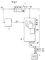
- the too monitoring system so here is the turbine generator unit designated as a whole by the reference number 1 and comprises a total of N Subsystems 11, 12, ..., 1N where N is any natural number.
- through Sensors not shown, are used during the operation of the system 1 for a fixed set of process variables B, U, S1, S2, ..., SN in Predefinable time intervals, for example every minute or every 10 Minutes, measured values recorded.
- the process variables B are company variables, for example the flow, the impeller position, the stator position, the electrical terminal power of the generator, the net head of the water.
- the process variables U are environmental variables, for example the Temperature of the ambient air or the water temperature in the inlet.
- each model Mi has as input variables in addition to the component sizes Si of this subsystem 1i at least one but usually several of the company sizes B and optionally one or more environmental variables U. Die Company sizes B therefore go into several or all of the Mi models.
- a model Mi is therefore created for each subsystem 1i.
- the entirety of the models Mi is designated M in FIG. 1.
- monitoring variables Ri 1,2, ..., N are determined, which are independent of the the respective operating point of the system.
- the Monitoring variables Ri each residuals, which are formed by difference from the current measured values for the component sizes Si and associated model values Yi.
- the time course of the monitoring variables Ri becomes monitoring and used to diagnose the system.
- the Time course of the monitoring variables Ri on an output unit 4 represented graphically.
- Based on the time course of the Monitoring parameters Ri can be used to assess wear and tear malfunctions are detected. With wear are there operational, usually slow-moving changes meant, for example in the shaft bearing or in the shaft seals as well z.
- a preliminary test 2 is carried out, in which it is checked whether at least the Measured values for those process variables that are company variables B, are within a predetermined range. Through this measure the efficiency of the process can be increased significantly. Because in the Operating phase of system 1 the current measured values for the operating parameters B are checked in each case before the models Mi for the subsystems 1i are evaluated, it is prevented that errors in the Propagate farm sizes B in models Mi for subsystems 1i and lead to false alarms or misdiagnoses. In addition, the Preliminary test 2 and the subsequent processing of the Mi models for the Subsystems 1i the identification of faulty process variables (fault isolation) reliably and easily.
- Preliminary check 2 of company sizes B also increases reliability wear monitoring for the individual subsystems 1i and facilitated thus clearly planning maintenance work.
- the method according to the invention can be divided into two Divide phases, namely into a learning phase and an operating phase.
- the Learning phase is used to create the models Mi for the subsystems 1i and
- system 1 is monitored using the Mi models. How the models Mi for the subsystems 1i based on those in the learning phase the measured values determined for the process variables can be determined in the EP-A-0 895 197 already cited is explained in detail and is therefore only described here briefly outlined. For more information, see EP-A-0 895 197, which is hereby incorporated into the present description.
- the Models Mi are the measured values for the process variables B, U, S1, ..., SN used, which are recorded during the learning phase.
- the learning phase denotes a time-limited operating period of the system 1, during which the system 1 in normal, that is, trouble-free operation is working.
- the choice of the learning phase can be based on experience. For example, after commissioning or a revision of the system 1 waited until typical running-in processes have been completed.
- the Learning phase is chosen so long that it has several different Includes operating points from the operating area of system 1 During the learning phase, the system is used on a variety of different Operating points operated, always ensured by checks is that the system 1 works correctly during the learning phase or that only such measured values are used to create the Mi models are, with the detection of the plant 1 worked error-free and trouble-free Has.
- At least one of the component sizes is selected from the set of component sizes Si that describe this subsystem 1i Si k is called.
- a model value Yi k is determined using the model Mi.
- At least some of the component sizes Si of this subsystem 1i as well as operating parameters B and possibly also environmental variables U are used as input variables of the model Mi.
- the case is explained below by way of example that exactly one of the component sizes, namely Si k , is the initial size of the model Mi.
- a linear static model structure is selected as the model structure for the model Mi, that is to say the process variable Si k is represented as a linear combination of the input variables of the model Mi.
- the coefficients of this linear combination denoted by a m , where m is a running index, are the model parameters for the model Mi.
- the sets (B, U, Si) T of measured values provide the determination equations for the model parameters a m . Since the number of sets of measured values is generally considerably larger than the number of model parameters a m , the system of the determination equations is over-determined. However, sufficient mathematical methods are known to use the determination equations to determine the best possible values for the model parameters a m . For example, methods of compensation calculation, the method of least squares, the method of singular value decomposition (SVD) or the principal component analysis (PCA) are suitable. Since such methods are well known, they are not explained in more detail here.
- Means of the model Mi, the associated model value (Yi k) T as the linear combination of the process parameters B, U, Si is now determined by the coefficients a m for each set (B, U, Si) T.
- the (Yi k ) T form a set of model values, where (Yi k ) T is the model value for the component size Si k for the time T.
- the model values (Yi k ) T are compared with the corresponding actual measured values for the component size (Si k ) T by forming a difference, and a residual r T is determined from each.
- a model error ⁇ is determined from the totality of the residuals r T , which is a measure of the quality of the model Mi.
- the model error ⁇ can be, for example, the normalized sum of the squares of the residuals.
- the model Mi is optimized by determining the model parameters a m and each time again determining the model error ⁇ until the model error ⁇ is minimal or falls below a predetermined limit. If this is achieved, the Mi model is sufficiently good for monitoring.
- the fluctuations in the residuals r T determined during the learning phase represent how large the deviation of the model value Yi k from the actual measured value Si k is typically. Therefore, in the normal operating phase, the confidence limits of the models or the threshold values for the monitoring variable are preferably determined on the basis of the residuals r T determined in the learning phase.
- the model structures used generally have no physical ones Importance.
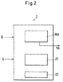
- the preliminary test 2 includes the following components: a machine model MA, its input variables Company sizes B and their output sizes are one Include machine model value YA for at least one of the operating variables; a range test 21, in which it is checked whether individual or Combinations of company sizes within the in the learning phase learned range of working points; a test 22, with which the Environmental variables are checked for freedom from interference.
- the MA machine model is essentially based on the same concept like the Mi models for the 1i subsystems.
- the machine model MA has as Input sizes Operating sizes B, for at regular intervals Measured values are recorded using the sensors.
- the task of MA machine model is selected for one or more Operating parameters to calculate machine model values, which then with the corresponding measured values for the operating parameters are compared can.
- the machine model MA only for exactly one selected company size B calculates a machine model value YA. It goes without saying that in practice for more than one company size B machine model values can be calculated, for which more than one machine model can be provided.
- Expediently with the Machine model or the machine models MA for those Operating parameters B machine model values YA calculated, which as Input sizes for models Mi of subsystems 1i can be used.
- the machine model MA like the models Mi, is based on the subsystem of measured values, which are recorded during the learning phase and saved.
- the machine model is therefore preferred Unlike the Mi models, MA is not a purely experimental model, but also takes into account known physical relationships between company sizes B and previous knowledge of plant 1.
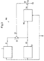
- FIG. 3 shows a concrete exemplary embodiment for the implementation of the Machine model MA schematically illustrated. It serves the Operating variable P, which is the electrical terminal power of the generator is to check that there is no interference. With Pl the actual value of the company size Denoted P, which can be measured, and with PS the target value of P, theoretically based on basic and prior knowledge, in Dependency on operating variables B is calculated. This target value PS is theoretically calculated by a module 31.
- the module 31 can for example include a physical model. It is also possible that the module 31 known physical relationships or empirically determined relationships between company sizes or prior knowledge of Plant 1 evaluates.
- the module 31 supplies a theoretical target value PS for the terminal power as a function of the operating parameters of the impeller position LA, stator position LE and net head HN, their current values recorded by measurement. With this calculation, more Sizes are taken into account, such as the numerical description of the Efficiency shell curves ⁇ h (LA, LE, HN) of the turbine, the efficiency ⁇ g of the generator and mechanical losses PM.
- the difference DP becomes metrological recorded actual value Pl and the theoretically calculated target value PS determined.
- This difference DP is also an operating variable B, which is here The embodiment described serves the freedom from interference Check company size P.
- Model parameters b0, b1, b2, b3, b4 of the model ME determined and optimized.
- the model ME is thus an experimental model with which the Deviation DP of the operating variable P from a theoretically determined target value is modeled.
- a large number of sets (LE, LA, HN, PI) T of measured values for the operating variables LE, LA, HN, PI are collected and stored, the index T being the successive sets of measured values (LE, LA, HN, PI) T indexed.
- the module 31 calculates the associated theoretical target value (PS) T.
- PS theoretical target value
- the sets (LE, LA, HN) T together with the associated value (PS) T provide the determination equations for the model parameters b0 to b4.
- a machine model value (YA) T for the deviation of the actual value Pl of the power from the target value PS of the power can then be determined for each index T.
- a model error ⁇ is determined from the totality of the residuals ⁇ T , which is a measure of the quality of the model ME.
- the model error ⁇ can be, for example, the normalized sum of the squares of the residuals.
- the model ME optimized until the model error ⁇ is minimal or a predetermined one Falls below the limit. If this is achieved, the ME model is good enough.
- the current machine model value YA for the difference DP between the measured power Pl and the Target value PS of the power determined.
- This machine model value YA is with the corresponding current measured value of this operating variable DP compared and a residual RA for plant 1 is determined, z. B. by Difference formation (point 33 in Fig. 3).
- This residual RA represents one Monitoring variable. Is the residual RA within a predetermined area, the so-called trust area, so the Company size P classified as trouble-free or error-free. Otherwise, there is a warning as will be explained later.
- warnings can be, for example: A malfunction due to HN contamination of bores and pipes or due to Air pocket; Disorders of LA or LE; Disturbance in the measurement of the Performance Pl; Decrease in hydraulic efficiency ⁇ h or Efficiency ⁇ g of the generator; bearing power loss too high, mechanical damage.
- machine models MA based on the in the Learning phase recorded measured values and based on basic knowledge or prior knowledge of Appendix 1.
- a model corresponding to the model ME in Fig. 3 created with which a machine model value for the deviation DQ of theoretically calculated flow QS from the actual, metrological detected flow QI can be determined. This machine model value will then with the actual deviation of the theoretical flow from measured flow compared, analogous to this as shown in Fig. 3 is.
- area test 21 (see FIG. 2) of preliminary test 2, it is checked whether individual or combinations of company sizes B within the in the learning phase learned range of work points.
- the area test 21 prevent unskilled states from becoming high residuals and thus too Lead to false warnings.
- This histogram 5 can be seen as a three-dimensional integer matrix represent and includes several classes 51, which in Fig. 4 as a cuboid are shown.
- Each class 51 corresponds to a combination of the three Company sizes LA, LE, HN, in which both LA, LE and HN each lie in a certain range of values. Consequently, everyone can Combination of values for LA, LE, HN classified in one of classes 51 become.
- Appendix 1 will be used by many operated different working points, so that also different Combinations of the values for the farm sizes LA, LE, HN occur.
- class 51 it should be assigned to. After the class 51 in which the combination of LA, LE, HN is to be classified, becomes the probability of the arrival of one belonging to this class Combination based on the relative calculated from histogram 5 Frequency of 51 events classified so far in this class.
- the histogram means 5 for each Class 51 determines the probability that an event, that is a combination of LA, LE, HN occurs, which belongs to this class 51.
- the area test 21 can also comprise a single area test, which also serves to avoid false warnings.
- This Individual range test is checked whether the individual measurement of a company size B lies within its specific measuring range, which is determined by a minimum and a maximum value is set. These are minimum and maximum values for example stored in the evaluation unit.
- the single range test is mainly used to check whether a Measurement is within the measuring range of the sensor or whether the measured value is physically possible. This allows Malfunctions of the sensors, for example on a cable break based, detect.
- the single range test can also be done by parent control device and the result be communicated to the evaluation unit.
- For the single area test can also use monitoring devices for the sensors that are already provided in Appendix 1.
- Model range test This will be for individual or all Models work areas and it is checked whether the Input variables of the respective model within the associated one Working area of the model.
- the test 22 (see FIG. 2) of the preliminary test 2 serves the Check surrounding variables U for freedom from interference.
- This test 22 is preferably by redundant measurement of the environmental variables U realized, for example, by an environmental variable U with several is determined by independent sensors.
- the test 22 for environmental parameters U also include single-range tests - analogous to they are described above - whereby it is checked whether the measured values are physically meaningful and / or within a specific measuring range.
- the Preliminary test 2 also other components can be implemented such as for example input filter for filtering the input variables and / or Residual filter for filtering the residuals.
- the different Models created based on the measured values recorded in the learning phase will be checked for instability when they are created. This can for example, by the position of the pole points Transfer function of the respective model is examined. Are natural also other known stability tests for the different models applicable.
- the Measured values for the component sizes S1, ..., SN which are specific for the Subsystems 11, ..., 1N are checked whether they are within their specific measuring range or are physically sensible. Thereby For example, errors on the sensors with which the measured values for the component sizes S1, ..., SN are determined, detect and locate.
- the process variables B, U, S1, ..., SN recorded measured values at predefinable time intervals. These are compared with model values or with machine model values, to determine the current values for the monitoring parameters. Several monitoring variables are preferably determined, each are a residual, which is the deviation of the model value or the Machine model value from the current measured value corresponding to it indicates.
- the index k indicates the component size Si k from the component sizes Si of the subsystem 1i for which the residual Ri k is determined, that is to say the output variable of the model Mi for the subsystem 1i.
- the residual or the residuals RA which are determined in the course of the preliminary test 2 with the aid of the machine model MA or the model ME and which specify the difference between the machine model value YA and the measured value for the corresponding operating variable B, serve as monitoring variables.
- the operating variables B which are monitored with machine models MA, are preferably the difference DP between the actual value Pl and the target value PS of the electrical terminal power P and the difference between the actual value and the target value of the flow Q.
- the models Mi, MA, ME are designed in such a way that they comply with the changes in the working point of Appendix 1, the monitoring variables Ri k and RA are independent of the current working point.
- a preferred embodiment of the Monitoring concept described which especially for the Early fault detection and maintenance planning is suitable.
- several categories for monitoring in which the Process variables depending on their current value or the current value of the associated residual can be divided. It are at least one category OK for normal operating condition, one Category EW for early warning, category WW for one Wear warning, a category UN for unknown conditions and one Category SW intended for a signal warning.
- a confidence interval is defined, that is to say threshold values are determined for the residuals Ri k , RA, the exceeding or falling below which the associated residual is no longer assessed as normal.
- These confidence limits or threshold values are preferably determined on the basis of those residuals or their fluctuations that were determined for the associated model Mi, MA, ME in the learning phase, because the residuals determined in the learning phase or their fluctuations represent a typical measure of how strong are the deviations of the model value Yi k or the machine model value YA from the corresponding measured value in the normal, trouble-free operating state.
- the threshold value for the residual Ri k , RA can be chosen to be equal to or slightly larger than the largest of the residuals that were determined in the learning phase for the corresponding model Mi, ME.
- the category UN for unknown states characterizes such a state in which an evaluation of the corresponding residual is dispensed with because of the great uncertainty regarding the significance of the residuals Ri k , RA.
- the category UN is selected in the following cases: One of the input variables of a model Mi is classified in the category EW in the preliminary test 2 (see further below); or during the preliminary test 2 it is detected that the redundant measurements for one or more of the environmental variables U are not compatible with one another; or the area test 21 shows that company sizes B or combinations of company sizes B are not within the range of operating points learned in the learning phase.
- the EW category for early warning is selected if a residual ri k or RA is outside its confidence interval.
- a residual ri k or RA is outside its confidence interval.
- a slowly progressing change is the reason for leaving the trust area, the operating personnel has the option of increasing or increasing the trust area for the corresponding residual RA or Ri k . This measure automatically means that the process variable that is monitored by this residual RA or Ri k is classified in the WW category for wear warning.
- the associated process size remains in the WW category. After a period of time depending on the wear and tear, this process variable will fall back into the EW category, which will inform the staff of the worsening wear and tear.
- the WW category is not used in the learning phase.
- the occurrence of the categories EW and WW for a process variable is saved and made visible on the output unit 4. In addition, the occurrence of the WW category is saved separately so that when the EW category reappears, it can be determined whether the confidence interval for the corresponding residual has already been changed.
- the threshold values for the category EW are preferably chosen so that that they are well below a critical limit at which Serious damage can result.
- Process variables B, U, S1, ..., SN that do not belong in any of the categories SW, UN, EW or WW are classified in the OK category for normal operating status. This is the case, for example, if the residual Ri k , with which the component size Si k is monitored, lies within its confidence interval and, moreover, no error has occurred during the preliminary test 2 and the residual RA (s) for those operating variables B which input variables for the Mi model belonging to Si k are within their confidence limits.
- the occurrence of the category OK is also saved and made visible on the output unit 4.
- the surveillance concept with the different categories, in particular with the categories EW and WW has the advantage that Signs of wear can be seen at a very early stage maintenance and maintenance work are planned and timely can be organized.
Landscapes
- Physics & Mathematics (AREA)
- General Physics & Mathematics (AREA)
- Engineering & Computer Science (AREA)
- Automation & Control Theory (AREA)
- Testing And Monitoring For Control Systems (AREA)
- Remote Monitoring And Control Of Power-Distribution Networks (AREA)
- Debugging And Monitoring (AREA)
Abstract
Description
- Fig. 1:
- eine Blockdarstellung eines Ausführungsbeispiels des erfindungsgemässen Verfahrens,
- Fig. 2:
- eine Blockdarstellung für die Vorprüfung in dem Ausführungsbeispiel nach Fig. 1,
- Fig. 3:
- eine Blockdarstellung zur Veranschaulichung einer Ausführungsform eines Maschinenmodells, und
- Fig. 4:
- eine Darstellung eines Ausführungsbeispiels eines dreidimensionalen Histogramms.
Claims (12)
- Verfahren zum Überwachen einer Anlage mit mehreren Subsystemen, die an variablen Arbeitspunkten betreibbar ist, mit den folgenden Schritten:dadurch gekennzeichnet, dass vor dem Bestimmen der Überwachungsgrösse (Ri,Rik) eine Vorprüfung (2) durchgeführt wird, in welcher überprüft wird, ob zumindest die Messwerte für diejenigen Prozessgrössen, die Betriebsgrössen (B) sind, innerhalb eines vorgegebenen Bereichs liegen.a) während des Betriebs der Anlage (1) werden für einen festgelegten Satz von Prozessgrössen (B,U,S1,...,SN) in vorgebbaren zeitlichen Abständen jeweils Messwerte erfasst,b) die in einer Lernphase für verschiedene Arbeitspunkte erfassten Messwerte werden zur Erstellung von Modellen (M1,M2,...,MN) für das Betriebsverhalten der Subsysteme (11,12,...,1N) herangezogen, wobei die Eingangsgrössen jedes Modells (M1,M2,...,MN) zumindest ein Teil der Prozessgrössen (B,U,S1,...,SN) sind und die Ausgangsgrösse jedes Modells einen Modellwert (Yi,Yik) für mindestens eine der Prozessgrössen umfasst, und wobei die Modelle (M1,M2,...,MN) durch Vergleichen der Modellwerte mit den Messwerten optimiert werden,c) in einer Betriebsphase wird mit Hilfe der Modelle (M1,M2,...,MN) in vorgebbaren zeitlichen Abständen zumindest eine Überwachungsgrösse (Ri,Rik) bestimmt, die unabhängig vom jeweils aktuellen Arbeitspunkt ist,d) der zeitliche Verlauf der Überwachungsgrösse (Ri,Rik) wird zur Überwachung der Anlage (1) herangezogen,
- Verfahren nach Anspruch 1, bei welchem für die Vorprüfung (2) ein Maschinenmodell (MA) bestimmt wird, dessen Eingangsgrössen Betriebsgrössen (B) sind und dessen Ausgangsgrössen einen Maschinenmodellwert (YA) für mindestens eine der Betriebsgrössen (B) umfassen.
- Verfahren nach Anspruch 2, bei welchem das Maschinenmodell (MA) mindestens ein Modell (ME) umfasst, mit welchem ein Maschinenmodellwert (YA) für die Abweichung (DP;DQ) des Messwerts (PI;QI) für eine Betriebsgrösse (P;Q) von einem theoretisch ermittelten Soll-Wert (PS;QS) für diese Betriebsgrösse (P;Q) bestimmt wird.
- Verfahren nach Anspruch 3, bei welchem das Modell (ME) für die Abweichung (DP;DQ) des Messwerts (PI,QI) von dem theoretisch ermittelten Soll-Wert (PS;QS) ein experimentelles Modell ist, welches anhand der in der Lernphase erfassten Messwerte erstellt und optimiert wird.
- Verfahren nach einem der Ansprüche 2-4, bei welchem das Maschinenmodell (MA) anhand der Messwerte erstellt wird, die in der Lernphase für verschiedene Arbeitspunkte erfasst werden, wobei durch Vergleichen des Maschinenmodellwerts (YA) mit dem ihm entsprechenden tatsächlichen Messwert eine Abweichungsgrösse bestimmt wird, und Modellparameter des Maschinenmodells (MA) so optimiert werden, dass ein aus den Abweichungsgrössen bestimmbarer Modellfehler minimal wird.
- Verfahren nach einem der Ansprüche 2-5, bei welchem während der Betriebsphase durch einen Vergleich des Maschinenmodellwerts (YA) mit dem entsprechenden aktuellen Messwert dieser Betriebsgrösse (B) ein Residuum (RA) für die Anlage bestimmt wird.
- Verfahren nach einem der vorangehenden Ansprüche, bei welchem während der Vorprüfung (2) die Umgebungsgrössen auf Störungsfreiheit überprüft werden.
- Verfahren nach einem der vorangehenden Ansprüche, bei welchem die Vorprüfung (2) einen Bereichstest (21) umfasst, in welchem überprüft wird, ob einzelne oder Kombinationen von Betriebsgrössen (B) innerhalb des in der Lernphase erlernten Bereichs von Arbeitspunkten liegen.
- Verfahren nach Anspruch 8, bei welchem der Bereichstest (21) anhand eines Histogramms (5) erfolgt, welches anhand der in der Lernphase erfassten Messwerte erstellt wird.
- Verfahren nach einem der vorangehenden Ansprüche, bei welchem mehrere Überwachungsgrössen bestimmt werden, die jeweils ein Residuum (Ri,Rik,RA) sind, welches die Abweichung eines Modellwerts (Yi,Yik) oder eines Maschinenmodellwerts (YA) von dem ihm entsprechenden aktuellen Messwert angibt.
- Verfahren nach einem der vorangehenden Ansprüche, bei welchem für die Überwachung mehrere Kategorien verwendet werden, in welche die Prozessgrössen jeweils in Abhängigkeit ihres aktuellen Wertes eingeteilt werden können, wobei zumindest eine Kategorie für den normalen Betriebszustand, eine Kategorie für eine Frühwarnung, eine Kategorie für eine Verschleisswarnung, eine Kategorie für unbekannte Zustände und und eine Kategorie für eine Signalwarnung vorgesehen sind.
- Verfahren nach einem der vorangehenden Ansprüche, wobei mindestens für eine Überwachungsgrösse (Ri,Rik,RA) ein Vertrauensbereich festgelegt wird, dieser Vertrauensbereich vergrössert werden kann, wenn die Überwachungsgrösse (Ri,Rik,RA) den ursprünglichen Vertrauensbereich verlässt, und die Vergrösserung des Vertrauensbereichs registriert wird.
Priority Applications (1)
| Application Number | Priority Date | Filing Date | Title |
|---|---|---|---|
| EP20010810783 EP1189126B1 (de) | 2000-09-14 | 2001-08-15 | Verfahren zum Überwachen einer Anlage |
Applications Claiming Priority (3)
| Application Number | Priority Date | Filing Date | Title |
|---|---|---|---|
| EP00810829 | 2000-09-14 | ||
| EP00810829 | 2000-09-14 | ||
| EP20010810783 EP1189126B1 (de) | 2000-09-14 | 2001-08-15 | Verfahren zum Überwachen einer Anlage |
Publications (3)
| Publication Number | Publication Date |
|---|---|
| EP1189126A2 true EP1189126A2 (de) | 2002-03-20 |
| EP1189126A3 EP1189126A3 (de) | 2003-12-17 |
| EP1189126B1 EP1189126B1 (de) | 2006-06-28 |
Family
ID=26074019
Family Applications (1)
| Application Number | Title | Priority Date | Filing Date |
|---|---|---|---|
| EP20010810783 Expired - Lifetime EP1189126B1 (de) | 2000-09-14 | 2001-08-15 | Verfahren zum Überwachen einer Anlage |
Country Status (1)
| Country | Link |
|---|---|
| EP (1) | EP1189126B1 (de) |
Cited By (7)
| Publication number | Priority date | Publication date | Assignee | Title |
|---|---|---|---|---|
| DE10241746B4 (de) * | 2002-09-10 | 2007-06-06 | Haag, Günter, Prof.Dr. | Verfahren zur zyklischen Qualitätsbewertung und Prozessüberwachung bei periodischen Produktionsprozessen |
| EP3062185A1 (de) * | 2015-02-27 | 2016-08-31 | Siemens Aktiengesellschaft | Modelbasiertes schutzsystem für elektrische systeme |
| WO2019077093A1 (de) * | 2017-10-20 | 2019-04-25 | Thyssenkrupp Marine Systems Gmbh | Verfahren und system zum auswerten eines betriebszustandes eines wasserfahrzeugs |
| WO2019120784A1 (de) * | 2017-12-22 | 2019-06-27 | Endress+Hauser Process Solutions Ag | Verfahren zum überwachen einer messstelle in einer anlage der prozessautomatisierung |
| DE102021213918A1 (de) | 2021-12-07 | 2023-06-07 | Kuka Deutschland Gmbh | Identifikation von Fehlerursachen auf Befehlsebene in Prozessen |
| DE102021133338A1 (de) | 2021-12-15 | 2023-06-15 | Balluff Gmbh | Verfahren zur Überwachung mittels maschinellem Lernen |
| DE102023109857A1 (de) * | 2023-04-19 | 2024-10-24 | Bayerische Motoren Werke Aktiengesellschaft | Verfahren zum Betreiben einer Produktionsanlage, Computerprogramm und Datenträger |
Families Citing this family (2)
| Publication number | Priority date | Publication date | Assignee | Title |
|---|---|---|---|---|
| DE102007019201B4 (de) * | 2007-04-20 | 2009-06-04 | Phoenix Contact Gmbh & Co. Kg | Abgleichen von Daten eines Steuer- und/oder Datenübertragungssystems und eines dieses repräsentierenden Systemmodells |
| US12482301B2 (en) * | 2022-06-08 | 2025-11-25 | The Boeing Company | Component maintenance prediction system with behavior modeling |
Family Cites Families (4)
| Publication number | Priority date | Publication date | Assignee | Title |
|---|---|---|---|---|
| FR2682208B1 (fr) * | 1991-10-07 | 1994-01-07 | Sollac | Procede et dispositif de surveillance de capteurs et de localisation de pannes d'un processus industriel. |
| DE19635033A1 (de) * | 1996-08-29 | 1998-03-12 | Siemens Ag | Verfahren zur Analyse eines Prozeßzustandes einer technischen Anlage |
| DE59702518D1 (de) * | 1997-06-06 | 2000-11-30 | Christoph H Tanner | Verfahren zur Prozesssteuerung und Gerätesteuersystem |
| DE59712546D1 (de) * | 1997-07-31 | 2006-04-06 | Sulzer Markets & Technology Ag | Verfahren zum Überwachen von Anlagen mit mechanischen Komponenten |
-
2001
- 2001-08-15 EP EP20010810783 patent/EP1189126B1/de not_active Expired - Lifetime
Cited By (8)
| Publication number | Priority date | Publication date | Assignee | Title |
|---|---|---|---|---|
| DE10241746B4 (de) * | 2002-09-10 | 2007-06-06 | Haag, Günter, Prof.Dr. | Verfahren zur zyklischen Qualitätsbewertung und Prozessüberwachung bei periodischen Produktionsprozessen |
| DE10241746B8 (de) * | 2002-09-10 | 2007-09-20 | Haag, Günter, Prof.Dr. | Verfahren zur zyklischen Qualitätsbewertung und Prozessüberwachung bei periodischen Produktionsprozessen |
| EP3062185A1 (de) * | 2015-02-27 | 2016-08-31 | Siemens Aktiengesellschaft | Modelbasiertes schutzsystem für elektrische systeme |
| WO2019077093A1 (de) * | 2017-10-20 | 2019-04-25 | Thyssenkrupp Marine Systems Gmbh | Verfahren und system zum auswerten eines betriebszustandes eines wasserfahrzeugs |
| WO2019120784A1 (de) * | 2017-12-22 | 2019-06-27 | Endress+Hauser Process Solutions Ag | Verfahren zum überwachen einer messstelle in einer anlage der prozessautomatisierung |
| DE102021213918A1 (de) | 2021-12-07 | 2023-06-07 | Kuka Deutschland Gmbh | Identifikation von Fehlerursachen auf Befehlsebene in Prozessen |
| DE102021133338A1 (de) | 2021-12-15 | 2023-06-15 | Balluff Gmbh | Verfahren zur Überwachung mittels maschinellem Lernen |
| DE102023109857A1 (de) * | 2023-04-19 | 2024-10-24 | Bayerische Motoren Werke Aktiengesellschaft | Verfahren zum Betreiben einer Produktionsanlage, Computerprogramm und Datenträger |
Also Published As
| Publication number | Publication date |
|---|---|
| EP1189126A3 (de) | 2003-12-17 |
| EP1189126B1 (de) | 2006-06-28 |
Similar Documents
| Publication | Publication Date | Title |
|---|---|---|
| EP0895197B1 (de) | Verfahren zum Überwachen von Anlagen mit mechanischen Komponenten | |
| EP0789861B1 (de) | Verfahren zur analyse von prozessdaten einer technischen anlage | |
| EP1543394B1 (de) | Vorrichtung und verfahren zur überwachung einer mehrere systeme umfassenden technischen anlage, insbesondere einer kraftwerksanlage | |
| EP2706422B1 (de) | Verfahren zur rechnergestützten Überwachung des Betriebs eines technischen Systems, insbesondere einer elektrischen Energieerzeugungsanlage | |
| EP1892597A1 (de) | Zustandsüberwachung von Maschinen und technischen Anlagen | |
| DE2622120A1 (de) | Verfahren und vorrichtung zur automatischen ueberwachung von anlagen | |
| EP0789864B1 (de) | Überwachungssystem für eine technische anlage | |
| WO2009135479A1 (de) | Vorrichtung und verfahren zur überwachung einer gasturbine | |
| DE69504437T2 (de) | Dauerzustandssensor | |
| EP3282399A1 (de) | Verfahren zur verbesserten erkennung von prozessanomalien einer technischen anlage sowie entsprechendes diagnosesystem | |
| EP1189126B1 (de) | Verfahren zum Überwachen einer Anlage | |
| DE102008037532A1 (de) | Automatische Detektion und Meldung von Verschleiss innerer Turbinenkomponenten | |
| EP2971769B1 (de) | R&i- schema eingabe | |
| EP4348825A1 (de) | Verfahren und überwachungseinrichtung zur zustandsüberwachung einer maschine | |
| DE102023207829B4 (de) | Verfahren und System zum Erkennen von Anomalien in einem Satz von Signalen | |
| DE102022134209B3 (de) | Verfahren, Diagnoseeinrichtung und System zum Überwachen eines Betriebs einer Brennkraftmaschine | |
| DE102018104665B4 (de) | Verfahren zum Betrieb einer Brennkraftmaschine, Steuereinrichtung und Brennkraftmaschine | |
| WO1999041650A1 (de) | Prozess- und anlagendiagnoseverfahren | |
| AT528105B1 (de) | Verfahren zur Ausfallprognose von Prüfanlagen | |
| EP4328693B1 (de) | Überwachungsverfahren für den betrieb einer anzahl von einer oder mehreren antriebseinrichtungen, insbesondere für den betrieb einer brennkraftmaschine, und system ausgebildet für das überwachungsverfahren | |
| EP3741196A1 (de) | Verfahren zur ermittlung einer fehlerursache bei einer landwirtschaftlichen arbeitsmaschine | |
| WO2019166377A1 (de) | Verfahren zum betrieb einer brennkraftmaschine, steuereinrichtung und brennkraftmaschine | |
| EP3553614A1 (de) | Verfahren zum erstellen eines modells einer technischen vorrichtung und verfahren zum überwachen einer technischen vorrichtung auf grundlage eines modells | |
| WO2022129440A1 (de) | System und verfahren zur thermischen überwachung grosser wälzlager | |
| DE102023113134A1 (de) | Verfahren und Vorrichtung zur Erfassung von Messdaten einer Maschine sowie Reifenheizpresse aufweisend eine Vorrichtung zur Erfassung von Messdaten |
Legal Events
| Date | Code | Title | Description |
|---|---|---|---|
| PUAI | Public reference made under article 153(3) epc to a published international application that has entered the european phase |
Free format text: ORIGINAL CODE: 0009012 |
|
| AK | Designated contracting states |
Kind code of ref document: A2 Designated state(s): AT BE CH CY DE DK ES FI FR GB GR IE IT LI LU MC NL PT SE TR |
|
| AX | Request for extension of the european patent |
Free format text: AL;LT;LV;MK;RO;SI |
|
| PUAL | Search report despatched |
Free format text: ORIGINAL CODE: 0009013 |
|
| AK | Designated contracting states |
Kind code of ref document: A3 Designated state(s): AT BE CH CY DE DK ES FI FR GB GR IE IT LI LU MC NL PT SE TR |
|
| AX | Request for extension of the european patent |
Extension state: AL LT LV MK RO SI |
|
| 17P | Request for examination filed |
Effective date: 20040519 |
|
| AKX | Designation fees paid |
Designated state(s): AT BE CH CY DE DK ES FI FR GB GR IE IT LI LU MC NL PT SE TR |
|
| GRAP | Despatch of communication of intention to grant a patent |
Free format text: ORIGINAL CODE: EPIDOSNIGR1 |
|
| GRAS | Grant fee paid |
Free format text: ORIGINAL CODE: EPIDOSNIGR3 |
|
| GRAA | (expected) grant |
Free format text: ORIGINAL CODE: 0009210 |
|
| AK | Designated contracting states |
Kind code of ref document: B1 Designated state(s): AT BE CH CY DE DK ES FI FR GB GR IE IT LI LU MC NL PT SE TR |
|
| PG25 | Lapsed in a contracting state [announced via postgrant information from national office to epo] |
Ref country code: IE Free format text: LAPSE BECAUSE OF FAILURE TO SUBMIT A TRANSLATION OF THE DESCRIPTION OR TO PAY THE FEE WITHIN THE PRESCRIBED TIME-LIMIT Effective date: 20060628 Ref country code: FI Free format text: LAPSE BECAUSE OF FAILURE TO SUBMIT A TRANSLATION OF THE DESCRIPTION OR TO PAY THE FEE WITHIN THE PRESCRIBED TIME-LIMIT Effective date: 20060628 Ref country code: NL Free format text: LAPSE BECAUSE OF FAILURE TO SUBMIT A TRANSLATION OF THE DESCRIPTION OR TO PAY THE FEE WITHIN THE PRESCRIBED TIME-LIMIT Effective date: 20060628 |
|
| REG | Reference to a national code |
Ref country code: GB Ref legal event code: FG4D Free format text: NOT ENGLISH |
|
| REG | Reference to a national code |
Ref country code: CH Ref legal event code: EP |
|
| REG | Reference to a national code |
Ref country code: CH Ref legal event code: NV Representative=s name: SULZER MANAGEMENT AG PATENTABTEILUNG/0067 |
|
| GBT | Gb: translation of ep patent filed (gb section 77(6)(a)/1977) |
Effective date: 20060628 |
|
| REG | Reference to a national code |
Ref country code: IE Ref legal event code: FG4D Free format text: LANGUAGE OF EP DOCUMENT: GERMAN |
|
| REF | Corresponds to: |
Ref document number: 50110315 Country of ref document: DE Date of ref document: 20060810 Kind code of ref document: P |
|
| PG25 | Lapsed in a contracting state [announced via postgrant information from national office to epo] |
Ref country code: BE Free format text: LAPSE BECAUSE OF NON-PAYMENT OF DUE FEES Effective date: 20060831 Ref country code: MC Free format text: LAPSE BECAUSE OF NON-PAYMENT OF DUE FEES Effective date: 20060831 |
|
| PG25 | Lapsed in a contracting state [announced via postgrant information from national office to epo] |
Ref country code: SE Free format text: LAPSE BECAUSE OF FAILURE TO SUBMIT A TRANSLATION OF THE DESCRIPTION OR TO PAY THE FEE WITHIN THE PRESCRIBED TIME-LIMIT Effective date: 20060928 Ref country code: DK Free format text: LAPSE BECAUSE OF FAILURE TO SUBMIT A TRANSLATION OF THE DESCRIPTION OR TO PAY THE FEE WITHIN THE PRESCRIBED TIME-LIMIT Effective date: 20060928 |
|
| PG25 | Lapsed in a contracting state [announced via postgrant information from national office to epo] |
Ref country code: ES Free format text: LAPSE BECAUSE OF FAILURE TO SUBMIT A TRANSLATION OF THE DESCRIPTION OR TO PAY THE FEE WITHIN THE PRESCRIBED TIME-LIMIT Effective date: 20061009 |
|
| PG25 | Lapsed in a contracting state [announced via postgrant information from national office to epo] |
Ref country code: PT Free format text: LAPSE BECAUSE OF FAILURE TO SUBMIT A TRANSLATION OF THE DESCRIPTION OR TO PAY THE FEE WITHIN THE PRESCRIBED TIME-LIMIT Effective date: 20061128 |
|
| NLV1 | Nl: lapsed or annulled due to failure to fulfill the requirements of art. 29p and 29m of the patents act | ||
| ET | Fr: translation filed | ||
| REG | Reference to a national code |
Ref country code: IE Ref legal event code: FD4D |
|
| PLBE | No opposition filed within time limit |
Free format text: ORIGINAL CODE: 0009261 |
|
| STAA | Information on the status of an ep patent application or granted ep patent |
Free format text: STATUS: NO OPPOSITION FILED WITHIN TIME LIMIT |
|
| 26N | No opposition filed |
Effective date: 20070329 |
|
| BERE | Be: lapsed |
Owner name: SULZER MARKETS AND TECHNOLOGY A.G. Effective date: 20060831 |
|
| PG25 | Lapsed in a contracting state [announced via postgrant information from national office to epo] |
Ref country code: GR Free format text: LAPSE BECAUSE OF FAILURE TO SUBMIT A TRANSLATION OF THE DESCRIPTION OR TO PAY THE FEE WITHIN THE PRESCRIBED TIME-LIMIT Effective date: 20060929 |
|
| PG25 | Lapsed in a contracting state [announced via postgrant information from national office to epo] |
Ref country code: TR Free format text: LAPSE BECAUSE OF FAILURE TO SUBMIT A TRANSLATION OF THE DESCRIPTION OR TO PAY THE FEE WITHIN THE PRESCRIBED TIME-LIMIT Effective date: 20060628 Ref country code: LU Free format text: LAPSE BECAUSE OF NON-PAYMENT OF DUE FEES Effective date: 20060815 |
|
| PG25 | Lapsed in a contracting state [announced via postgrant information from national office to epo] |
Ref country code: CY Free format text: LAPSE BECAUSE OF FAILURE TO SUBMIT A TRANSLATION OF THE DESCRIPTION OR TO PAY THE FEE WITHIN THE PRESCRIBED TIME-LIMIT Effective date: 20060628 |
|
| PGFP | Annual fee paid to national office [announced via postgrant information from national office to epo] |
Ref country code: CH Payment date: 20100824 Year of fee payment: 10 |
|
| PGFP | Annual fee paid to national office [announced via postgrant information from national office to epo] |
Ref country code: DE Payment date: 20100823 Year of fee payment: 10 Ref country code: AT Payment date: 20100812 Year of fee payment: 10 Ref country code: IT Payment date: 20100824 Year of fee payment: 10 Ref country code: FR Payment date: 20100901 Year of fee payment: 10 |
|
| PGFP | Annual fee paid to national office [announced via postgrant information from national office to epo] |
Ref country code: GB Payment date: 20100819 Year of fee payment: 10 |
|
| REG | Reference to a national code |
Ref country code: CH Ref legal event code: PL |
|
| GBPC | Gb: european patent ceased through non-payment of renewal fee |
Effective date: 20110815 |
|
| PG25 | Lapsed in a contracting state [announced via postgrant information from national office to epo] |
Ref country code: CH Free format text: LAPSE BECAUSE OF NON-PAYMENT OF DUE FEES Effective date: 20110831 Ref country code: LI Free format text: LAPSE BECAUSE OF NON-PAYMENT OF DUE FEES Effective date: 20110831 |
|
| REG | Reference to a national code |
Ref country code: FR Ref legal event code: ST Effective date: 20120430 |
|
| PG25 | Lapsed in a contracting state [announced via postgrant information from national office to epo] |
Ref country code: IT Free format text: LAPSE BECAUSE OF NON-PAYMENT OF DUE FEES Effective date: 20110815 |
|
| REG | Reference to a national code |
Ref country code: DE Ref legal event code: R119 Ref document number: 50110315 Country of ref document: DE Effective date: 20120301 |
|
| PG25 | Lapsed in a contracting state [announced via postgrant information from national office to epo] |
Ref country code: FR Free format text: LAPSE BECAUSE OF NON-PAYMENT OF DUE FEES Effective date: 20110831 Ref country code: GB Free format text: LAPSE BECAUSE OF NON-PAYMENT OF DUE FEES Effective date: 20110815 |
|
| REG | Reference to a national code |
Ref country code: AT Ref legal event code: MM01 Ref document number: 331983 Country of ref document: AT Kind code of ref document: T Effective date: 20110815 |
|
| PG25 | Lapsed in a contracting state [announced via postgrant information from national office to epo] |
Ref country code: AT Free format text: LAPSE BECAUSE OF NON-PAYMENT OF DUE FEES Effective date: 20110815 |
|
| PG25 | Lapsed in a contracting state [announced via postgrant information from national office to epo] |
Ref country code: DE Free format text: LAPSE BECAUSE OF NON-PAYMENT OF DUE FEES Effective date: 20120301 |