EP1189304A2 - Antennenanordnung und Kartenmodul zur Funkkommunikation mit einer derartigen Antenne - Google Patents
Antennenanordnung und Kartenmodul zur Funkkommunikation mit einer derartigen Antenne Download PDFInfo
- Publication number
- EP1189304A2 EP1189304A2 EP01307973A EP01307973A EP1189304A2 EP 1189304 A2 EP1189304 A2 EP 1189304A2 EP 01307973 A EP01307973 A EP 01307973A EP 01307973 A EP01307973 A EP 01307973A EP 1189304 A2 EP1189304 A2 EP 1189304A2
- Authority
- EP
- European Patent Office
- Prior art keywords
- pattern
- antenna
- radio communication
- antenna pattern
- type antenna
- Prior art date
- Legal status (The legal status is an assumption and is not a legal conclusion. Google has not performed a legal analysis and makes no representation as to the accuracy of the status listed.)
- Granted
Links
Images





Classifications
-
- H—ELECTRICITY
- H01—ELECTRIC ELEMENTS
- H01Q—ANTENNAS, i.e. RADIO AERIALS
- H01Q1/00—Details of, or arrangements associated with, antennas
- H01Q1/12—Supports; Mounting means
- H01Q1/22—Supports; Mounting means by structural association with other equipment or articles
- H01Q1/26—Supports; Mounting means by structural association with other equipment or articles with electric discharge tube
-
- H—ELECTRICITY
- H01—ELECTRIC ELEMENTS
- H01Q—ANTENNAS, i.e. RADIO AERIALS
- H01Q1/00—Details of, or arrangements associated with, antennas
- H01Q1/12—Supports; Mounting means
- H01Q1/22—Supports; Mounting means by structural association with other equipment or articles
- H01Q1/2258—Supports; Mounting means by structural association with other equipment or articles used with computer equipment
- H01Q1/2275—Supports; Mounting means by structural association with other equipment or articles used with computer equipment associated to expansion card or bus, e.g. in PCMCIA, PC cards, Wireless USB
-
- G—PHYSICS
- G06—COMPUTING OR CALCULATING; COUNTING
- G06F—ELECTRIC DIGITAL DATA PROCESSING
- G06F1/00—Details not covered by groups G06F3/00 - G06F13/00 and G06F21/00
- G06F1/16—Constructional details or arrangements
- G06F1/1613—Constructional details or arrangements for portable computers
- G06F1/1632—External expansion units, e.g. docking stations
-
- H—ELECTRICITY
- H01—ELECTRIC ELEMENTS
- H01Q—ANTENNAS, i.e. RADIO AERIALS
- H01Q1/00—Details of, or arrangements associated with, antennas
- H01Q1/12—Supports; Mounting means
- H01Q1/22—Supports; Mounting means by structural association with other equipment or articles
- H01Q1/24—Supports; Mounting means by structural association with other equipment or articles with receiving set
- H01Q1/241—Supports; Mounting means by structural association with other equipment or articles with receiving set used in mobile communications, e.g. GSM
- H01Q1/242—Supports; Mounting means by structural association with other equipment or articles with receiving set used in mobile communications, e.g. GSM specially adapted for hand-held use
- H01Q1/243—Supports; Mounting means by structural association with other equipment or articles with receiving set used in mobile communications, e.g. GSM specially adapted for hand-held use with built-in antennas
-
- H—ELECTRICITY
- H01—ELECTRIC ELEMENTS
- H01Q—ANTENNAS, i.e. RADIO AERIALS
- H01Q1/00—Details of, or arrangements associated with, antennas
- H01Q1/36—Structural form of radiating elements, e.g. cone, spiral, umbrella; Particular materials used therewith
-
- H—ELECTRICITY
- H01—ELECTRIC ELEMENTS
- H01Q—ANTENNAS, i.e. RADIO AERIALS
- H01Q1/00—Details of, or arrangements associated with, antennas
- H01Q1/36—Structural form of radiating elements, e.g. cone, spiral, umbrella; Particular materials used therewith
- H01Q1/38—Structural form of radiating elements, e.g. cone, spiral, umbrella; Particular materials used therewith formed by a conductive layer on an insulating support
-
- H—ELECTRICITY
- H01—ELECTRIC ELEMENTS
- H01Q—ANTENNAS, i.e. RADIO AERIALS
- H01Q21/00—Antenna arrays or systems
- H01Q21/24—Combinations of antenna units polarised in different directions for transmitting or receiving circularly and elliptically polarised waves or waves linearly polarised in any direction
-
- H—ELECTRICITY
- H01—ELECTRIC ELEMENTS
- H01Q—ANTENNAS, i.e. RADIO AERIALS
- H01Q21/00—Antenna arrays or systems
- H01Q21/28—Combinations of substantially independent non-interacting antenna units or systems
-
- H—ELECTRICITY
- H01—ELECTRIC ELEMENTS
- H01Q—ANTENNAS, i.e. RADIO AERIALS
- H01Q9/00—Electrically-short antennas having dimensions not more than twice the operating wavelength and consisting of conductive active radiating elements
- H01Q9/04—Resonant antennas
- H01Q9/0407—Substantially flat resonant element parallel to ground plane, e.g. patch antenna
- H01Q9/0421—Substantially flat resonant element parallel to ground plane, e.g. patch antenna with a shorting wall or a shorting pin at one end of the element
-
- H—ELECTRICITY
- H01—ELECTRIC ELEMENTS
- H01Q—ANTENNAS, i.e. RADIO AERIALS
- H01Q9/00—Electrically-short antennas having dimensions not more than twice the operating wavelength and consisting of conductive active radiating elements
- H01Q9/04—Resonant antennas
- H01Q9/30—Resonant antennas with feed to end of elongated active element, e.g. unipole
- H01Q9/42—Resonant antennas with feed to end of elongated active element, e.g. unipole with folded element, the folded parts being spaced apart a small fraction of the operating wavelength
Definitions
- This invention relates to antenna devices and to radio communication card modules having antenna devices.
- AV data audio video data
- radio communication systems for next generation such as the 5 GHz narrow-band radio communication system proposed in IEEE 802.1a, 2.45 GHz band radio LAN system proposed in IEEE 802.1b, and a short-range radio communication system termed Bluetooth are worthy of notice.
- the main apparatus 2 can transmit/receive data among apparatuses constituting the system when the radio LAN card 50 is installed to a slot 3 thereof, as shown in Fig.1.
- the radio LAN card 50 has a module main body 51 and an antenna unit 52 provided at one side thereof.
- the radio LAN card 50 has a radio communication controlling unit and a high frequency signal processing unit built therein.
- the radio LAN card 50 is electrically connected to the main apparatus 2 when the module main body 51 is installed to the slot 3 thereof. At this time, the antenna unit 52 is exposed to the outside to transmit/receive data among the apparatuses, as shown in Fig.2.
- radio LAN In the radio LAN system proposed in IEEE 802.1b, a radio LAN card conforming to the PCMCIA (Personal Computer Memory Card International Association) is widely utilized. On the other hand, in the Bluetooth radio communication network system, a small-sized radio LAN card having radio communication function has been developed.
- PCMCIA Personal Computer Memory Card International Association
- the antenna unit 52 protrudes from the side of the main apparatus 2 by a length 1 being approximately 25 mm, as shown in Fig.2. Furthermore, an external antenna, not shown, is mounted to the antenna unit 52 so as not to be prevented from transmitting/receiving data among the apparatuses by the main apparatus 2, which undesirably makes the main apparatus 2 complicated and enlarged.
- the protruding length of the radio LAN card 50 is too large and cumbersome. So, the radio LAN card 50 is often broken when hit by the user by mistake. Furthermore, even though the radio LAN card 50 can add radio communication function to various apparatuses, the configuration shape is restricted, which undesirably raise the difficulty in designing with high degree of freedom.
- the inversed F type antenna has an antenna pattern, a short circuit forming pattern, and a feeding pattern.
- the short circuit forming pattern has an end thereof connected to an end of the antenna pattern perpendicular thereto, and the feeding pattern has an end thereof connected to the halfway portion of the antenna pattern in parallel with the short circuit forming pattern.
- the inversed F type antenna of an inversed F shape is configured.
- the direction of the main polarized wave of the inversed F type antenna crosses perpendicular to the antenna pattern thereof.
- Fig.3 shown a schematic view of an antenna device 60 in which a pair of inversed F type antenna patterns being a first inversed F type antenna pattern 62 and a second inversed F type antenna pattern 63 are formed perpendicular to each other.
- the direction of the main polarized wave of the first inversed F type antenna pattern 62 is a1 and that of the second inversed F type antenna pattern 63 is b1, thereby configuring polarization diversity.
- configured antenna device 60 requires a height h, which makes it difficult to reduce the size thereof. So, in case the antenna device 60 is used as the antenna unit 52, the radio LAN card 50 is undesirably enlarged.
- the radio communication function is added to various apparatuses such as a digital still camera, a video camera or a portable audio apparatus as an AV apparatus, a household electrical apparatus, and an entertainment robot, as well as a radio communication apparatus and an apparatus in a computer system.
- a portable apparatus forming a plurality of communication ports or installing hardware conforming to various standards induce enlargement and high price of the apparatus, which significantly prevents the diffusion thereof.
- the radio communication function is significantly affected by interference generated at the same frequency band or at different frequency bands.
- the radio LAN card is used in above-described various apparatuses as well as a radio communication apparatus and an apparatus in a computer system, a small-sized antenna device which does not protrude so much from a main apparatus and has polarization diversity characteristics is required extremely.
- Embodiments of the present invention relate to a card-shaped radio communication module which may be installed to electrical apparatuses such as a personal computer, a wireless telephone, and an audio apparatus, and adds radio communication function there to, and an antenna device which is comfortably used in the card-shaped radio communication module.
- Embodiments of the present invention can overcome or at least alleviate the above-mentioned drawbacks by providing a small-sized antenna device which has polarization diversity characteristics.
- Embodiments of the present invention can provide a radio communication card module which has a small-sized antenna unit whose protruding length from a main apparatus is made minimum when installed and adding radio communication function thereto and has polarization diversity characteristics.
- an antenna device which has at least a first antenna pattern being an inversed F type antenna pattern and a second antenna pattern being a meander type antenna pattern formed on the main surface of a dielectric substrate by printed wiring.
- the inversed F type antenna pattern and the meander type antenna pattern are wired so that the directions of the main polarized wave of these antenna patterns cross perpendicular to each other.
- the meander type antenna pattern has a point in the vicinity of the opened end thereof connected to a circuit unit formed on the dielectric substrate or to a short circuit forming pattern formed on the dielectric substrate between the inversed F type antenna pattern and the meander type antenna pattern.
- the antenna device having the inversed F type antenna pattern and the meander type antenna pattern whose directions of the main polarized wave cross perpendicular to each other, the antenna device can be reduced in size and configure polarization diversity, and whose antenna characteristics is not deteriorated when affected by the housing shape of a main apparatus or material thereof when installed to the main apparatus, which can realize transmission/reception of data or information with high accuracy. Furthermore, with the antenna device, the short circuit forming pattern can prevent the inversed F type antenna pattern and the meander type antenna pattern from affecting each other. Furthermore, with the antenna device, by forming a ground pattern and a circuit unit in the vicinity of the meander type antenna pattern, shunt capacitance is add to reduce the resonance frequency, while realizing impedance matching of the meander type antenna pattern.
- a radio communication card module which has a module main body having a radio communication controlling unit and a high frequency signal processing unit built therein, an antenna unit, and a connector unit.
- the antenna unit is mounted to a second side located on the opposite side of a first side which has the connector unit, and a dielectric substrate which has at least a first antenna pattern being an inversed F type antenna pattern and a second antenna pattern being a meander type antenna pattern formed on the main surface of the dielectric substrate by printed wiring is supported perpendicular to the insertion direction toward a main apparatus.
- the radio communication card module is installed to a slot of the main apparatus and the connector unit is connected to a connector unit of the main apparatus, and adds radio communication function to the main apparatus.
- the antenna unit protrudes from the side of the main apparatus by a length being the thickness thereof along the side direction of the main apparatus.
- the radio communication card module having the inversed F type antenna pattern and the meander type antenna pattern whose directions of the main polarized wave cross perpendicular to each other, the radio communication card module can be reduced in size and configure polarization diversity, and whose antenna characteristics is not deteriorated when affected by the housing shape of a main apparatus or material thereof when installed to the main apparatus, which can realize transmission/reception of data or information with high accuracy.
- An antenna device 1 according to the present invention is removably mounted to a radio communication card module 4 which adds radio communication function to a personal computer 2 or a main apparatus 2 when installed thereto.
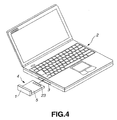
- the radio communication card module 4 adds radio communication function to the main apparatus 2 when installed to a slot 3 thereof, as shown in Figs.4 and 5.
- the radio communication card module 4 is removed when it is not necessary.
- the radio communication card module 4 adds radio communication function to the main apparatus 2 so that the main apparatus 2 can transmit/receive data among apparatuses constituting a radio communication network system by radio communication.
- the radio communication card module 4 receives data or information from apparatuses via the internet and transmits the received data or information to the main apparatus 2 or to apparatuses included in the internet. Having the antenna device 1 of high performance mounted thereto, the radio communication card module 4 can transmit/receive radio information with high accuracy.
- the radio communication card module 4 has the protruding length of the antenna device 1 from the main apparatus 2 made minimum. So, the antenna device 1 is not considered to be cumbersome, and is not broken so often due to a hit by the user.
- the radio communication card module 4 has a card-sized module main body 5 and an antenna device 1 provided at one side thereof.
- the radio communication card module 4 has a first side 5a which is to be installed to the main apparatus 2, and a second side 5b located on the opposite side of the first side 5a to which the antenna device 1 is removably mounted.
- the module main body 5 has built therein a circuit board 22 which has formed thereon a high frequency signal processing unit, a CPU and a ROM constituting a baseband signal processing unit and a controlling unit, a general purpose LSI, a memory element for performing storage function, and a power supply controlling unit, the details of which is omitted.
- the main surface of the first side 5a of the module main body 5 has formed thereon a connection terminal 23.
- the connection terminal 23 may be a plug-shaped terminal conforming to the standard of the radio communication card module 4.
- the connection terminal 23 is connected to a connection terminal formed inside the slot 3.
- radio communication card module 4 is connected to the main apparatus 2.
- the antenna device 1 protrudes from the side of the main apparatus 2 by a length t being the thickness thereof along the side direction of the main apparatus, as shown in Fig.5.
- the antenna device 1 is so formed as to be reduced in thickness, the details of which will be described later.
- the protruding length t of the antenna device 1 from the main apparatus 2 is approximately 4 mm, which is about one sixth of the protruding length 1 of the radio LAN card 50 being approximately 25 mm.
- the antenna device 1 of the radio communication card module 4 Since the antenna device 1 of the radio communication card module 4 is located in the vicinity of the main apparatus 2, the antenna characteristics of the antenna device 1 may be deteriorated when affected by the housing shape of the main apparatus 2 or material thereof. So, the antenna device 1 of the radio communication card module 4 has built therein two antennas, the directions of the main polarized wave of which are different from each other to configure polarization diversity. Thus, the radio communication card module 4 having the antenna device 1 can transmit/receive data or information with high accuracy irrespective of the antenna characteristics. The radio communication card module 4 has the antenna device 1 having these two antennas so formed as to be reduced in size, which can make the antenna device 1 supported with stability by the main apparatus 2.
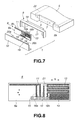
- a recess 6 for supporting the antenna device 1 at the second side 5b of the module main body 5, as shown in Fig.7.
- a pair of coaxial jack terminals 7 adjacent to each other at the recess 6 along the width direction of the module main body 5, the details of which is omitted.
- the jack terminals 7 are connected to the circuit board 22 built in the module main body 5, and data is transmitted between the antenna device 1 and the module main body 5 via the jack terminals 7.
- the antenna device 1 is fed with power via the jack terminals 7.
- the antenna device 1 has an antenna substrate 8, a holding member 9 being a housing for holding the antenna substrate 8, a front member 10, and a pair of coaxial plug connectors 16 (16a, 16b).
- the holding member 9 is of a box-shaped configuration with its front side and bottom side opened.
- the holding member 9 has formed therein an opening 17 for holding the antenna substrate 8, and a terminal cover 18 is unitedly formed at the rear side thereof.
- the front member 10 shuts the opened front and bottom sides of the holding member 9, and has a supporting member 19 for supporting the antenna substrate 8 which is unitedly formed at the protruding bottom formed at the rear side thereof.
- the front member 10 also has a pair of protruding studs 20 (20a, 20b) to be coupled to the holding member 9 which are unitedly formed at both sides of the supporting member 19.
- the holding member 9 and front member 10 perpendicularly holds the antenna substrate 8.
- the main surface 8a of the antenna substrate 8 has formed thereon a first antenna pattern 11, a second antenna pattern 13, and a short circuit forming pattern 12 located therebetween.
- the other main surface 8b of the antenna substrate 8 has mounted thereto the coaxial plug connectors 16 perpendicularly.
- the antenna substrate 8 is made of burning resistance glass material of FR4 grade (flame retardant grade) being generally an epoxy resin copper-clad laminate substrate. And the patterns, to be described later, are formed by printing or etching method.
- the antenna substrate 8 uses an FR 4 copper-clad laminate substrate having a dielectric constant of approximately 4. Also, a polytetrafluoroethylene (Teflon being a trade name)-ceramic combined substrate and a ceramic substrate can also be used as the substrate.
- the antenna substrate 8 using a substrate having a high dielectric constant reduces the resonance frequency, which can miniaturize the antenna device 1.
- the antenna substrate 8 can also use the Teflon (trade name), etc. having a high dielectric constant and a low dielectric dissipation factor at a significantly high frequency band more than 10 GHz.
- the antenna substrate 8 is a miniaturized substrate having high performance.
- the outside dimension of the antenna substrate 8 is 42 mm ⁇ 9.5 mm ⁇ 0.8 mm.
- the first antenna pattern 11 is an inversed F type antenna pattern formed on the left portion of the main surface 8a of the antenna substrate 8,
- the first antenna pattern 11 or the inversed F type antenna pattern 11 has a resonating pattern, a short circuit forming pattern, and a feeding pattern.
- the resonating pattern extends directly from a point near the left edge to a point near the center portion along the upside edge on the main surface 8a.
- the short circuit forming pattern extends downward directly from the center portion end of the resonating pattern perpendicular thereto.
- the feeding pattern extends downward directly from the halfway portion of the resonating pattern perpendicular thereto in parallel with the short circuit forming pattern.
- the inversed F type antenna of an inversed F shape facing the bottom of the antenna substrate 8 is formed.
- the direction of the main polarized wave of the inversed F type antenna pattern 11 is parallel with upside to downside direction of the main surface 8a of the antenna substrate 8, as shown by an arrow a in Fig.8.
- the short circuit forming pattern 12 is located substantially at the center portion of the main surface 8a of the antenna substrate 8 and extends from upside to downside directly.
- the short circuit forming pattern 12 is located between the first antenna pattern 11 and the second antenna pattern 13 to electrically insulate these patterns, thereby preventing them from affecting each other.
- the short circuit forming pattern 12 allows the first antenna pattern 11 and second antenna pattern 13 to be formed closely with each other, which can miniaturize the antenna substrate 8.
- the second antenna pattern 13 is a meander type antenna pattern which is folded alternately to form a zigzag line, and is formed on the left portion of the main surface 8a separated by the short circuit forming pattern 12.
- the direction of the main polarized wave of the second antenna pattern 13 or the meander type antenna pattern 13 is parallel with left to right direction of the main surface 8a of the antenna substrate 8, as shown by an arrow b in Fig.8.
- the direction of the main polarized wave of the meander type antenna pattern 13 crosses perpendicular to that of the inversed F type antenna pattern 11, thereby configuring polarization diversity.
- the height of the antenna substrate 8 using the meander type antenna pattern 13 is less than half that of the antenna device 60 in which a pair of inversed F type antennas are formed perpendicular to each other to configure polarization diversity.
- the antenna substrate 8 may be formed so that the direction of the main polarized wave of the meander type antenna pattern 13 is made equal to that of the inversed F type antenna pattern 11, thereby configuring polarization diversity in which the directions of the main polarized wave of the inversed F type antenna pattern 11 and meander type antenna pattern 13 are equal.
- the main surface 8a of the antenna substrate 8 has formed thereon a ground pattern 14 under the meander type antenna pattern 13.
- the ground pattern 14 is formed in the vicinity of a feeding end of the meander type antenna pattern 13 with a clearance being 0.2 mm therebetween in this embodiment.
- ground pattern 14 adds shunt capacitance to reduce the resonance frequency, which can miniaturize the antenna device 1, while realizing impedance matching of the second antenna pattern 13.
- the antenna substrate 8 may not have formed thereon the ground pattern 14 for adding the shunt capacitance at a predetermined frequency specification.
- the antenna substrate 8 has formed thereon a circuit unit 21 for performing high frequency signal modulation and amplification, which has chips or electronic parts such as coils, capacitors, resistors, short resistors, etc.
- the circuit unit 21 is connected to a point in the vicinity of the opened end of the meander type antenna pattern 13.
- the circuit unit 21 reduces the resonance frequency along with the ground pattern 14, which can miniaturize the antenna device 1, while realizing impedance matching of the second antenna pattern 13.
- the antenna substrate 8 can form the meander type antenna pattern 13 in a region smaller than that required for performing resonance, which is approximately from ⁇ /2 to ⁇ /4 in length.
- the antenna substrate 8 may have formed thereon another short circuit forming pattern to directly connect the short circuit forming pattern 12 to a point in the vicinity of the opened end of the second antenna pattern 13 instead of forming the circuit unit 21.
- the impedance matching can also be realized and the resonance frequency can be reduced.
- the main surface 8a of the antenna substrate 8 has formed thereon a feeding pattern 15 under the center portion thereof.
- the feeding pattern 15 has arranged thereon lands to which the ends of the short circuit forming pattern and feeding pattern of the inversed F type antenna pattern 11, feeding end of the short circuit forming pattern 12, and feeding end of the meander type antenna pattern 13 are connected.
- the coaxial plug connectors 16a, 16b have their basal portions inserted through the holes, and connected to the feeding pattern 15 by soldering.
- Each of the coaxial plug connectors 16a, 16b has an input/output terminal at the core thereof, and has a ground terminal at the outer circumference thereof.
- the input/output terminal and ground terminal of each of the coaxial plug connectors 16a, 16b are connected to the lands of the feeding pattern 15 by soldering.
- each of the coaxial plug connectors 16a, 16b protrudes perpendicular to the antenna substrate 8.
- the ends of the coaxial plug connectors 16a, 16b protrude from the terminal cover 18 to be exposed to outside.
- Each of the ends of the coaxial plug connectors 16a, 16b is configured to be a plug.
- each end of the coaxial plug connectors 16a, 16b is fit into each of the jack terminals 7, as will be described hereinafter.
- the coaxial plug connectors 16a, 16b being connecting means connect the antenna device 1 to the module main body 5, and transmit/receive data therebetween and feed the antenna device 1 with power.
- the antenna device 1 is engaged in the recess 6 of the module main body 5, when the coaxial plug connectors 16a, 16b protruding from the terminal cover 18 are inserted to the jack terminals 7 of the module main body 5.
- the antenna device 1 is mounted to the module main body 5 to configure the radio communication card module 4.
- the antenna device 1 uprises at the side of the module main body 5 along the side direction thereof.
- the antenna device 1 can be detached from the module main body 5 by pulling out the antenna device 1 from the module main body 5. So, the radio communication card module 4 can be handled easily by separating the antenna device 1 and module main body 5 when not in use.
- the radio communication card module 4 it is required that the first and second antenna patterns 11, 13 are not affected by metal portions of the module main body 5.
- the resonating pattern of the inversed F type antenna pattern 11 is so formed as to be separated from the metal portions of the module main body 5.
- the meander type antenna pattern 13 is formed so that the feeding end thereof is located in the vicinity of the metal portions of the module main body 5, while the opened end thereof is separated from the metal portions of the module main body 5.
- the meander type antenna pattern 13 is so formed as to be coupled to the ground of the module main body 5, which can make it possible to obtain a desired resonance frequency.
- the first and second antenna patterns 11, 13 are set to be used in the same frequency band.
- the first and second antenna patterns 11, 13 may be set to be used in different frequency bands.
- the radio communication card module 4 the inversed F type antenna pattern 11 whose resonating pattern length can be set large is used for low frequency band, while the meander type antenna pattern 13 being used for high frequency band.
- the radio communication card module 4 it is possible to set the first and second antenna patterns 11, 13 so that either of them can be used in case it is not necessary to configure polarization diversity. With the radio communication card module 4, it is not necessary to form the first and second antenna patterns 11, 13 on the antenna substrate 8 in above-described manner, and, for example, they may be formed in regions having the same area. With the radio communication card module 4, the second antenna pattern 13 may be a chip type antenna pattern.
- Fig.9A and Fig.9B show the measurement result of the voltage standing wave ratio (VSWR) of the impedance matching characteristics.
- Fig.9A shows the result of the inversed F type antenna pattern 11, while Fig.9B shows that of the meander type antenna pattern 13.
- the antenna device 1 is so designed as to be used for 2.4 GHz to 2.48 GHz band which is the standard band employed by the radio communication card module 4. The smaller the VSWR is, the better the antenna characteristics becomes.
- each value of the VSWR of the inversed F type antenna pattern 11 and meander type antenna pattern 13 is desirably both less than 2.
- the antenna device 1 may be mounted to a subminiature radio communication module 30 shown in Fig.10, whose outside dimension is 50.00 mm ⁇ 21.45 mm.
- the subminiature radio communication module 30 has a housing 31 which has built therein various elements for realizing storage function and radio communication function similar to a memory stick (trade name).
- the housing 31 has a terminal 32, a memory 33 for performing storage function, an LSI 34 for baseband signal processing, and an RF module 35 for high frequency signal processing.
- an antenna unit 36 is configured by the antenna substrate 8 of the antenna device 1.
- above-described elements including the antenna substrate 8 are mounted to a flexible circuit board 37, and the antenna substrate 8 is so supported by the housing 31 as to uprise therein.
- the subminiature radio communication module 30 further has a radio wave absorbent 39 for embedding the region among the LSI 34, the RF module 35, other elements 38, and other region. Above described elements are mounted to the flexible circuit board 37 in the housing 31 in order of above description, which can reduce the internal loss of the subminiature radio communication module 30. With the subminiature radio communication module 30, hypofunction due to interference over the antenna unit 36 by the RF module 35 is suppressed.
- the subminiature radio communication module 30 is installed to the main apparatus 2 by connecting the terminal 32 thereto.
- the antenna unit 36 uprises at the side of the main apparatus 2 along the side direction thereof. Since the antenna substrate 8 uprises via the flexible circuit board 37, the protruding length from the main apparatus 2 can be minimized.
- the antenna device when the module main body is inserted to the main apparatus and supported therein, the antenna device is supported perpendicular to the insertion direction, and the protruding length of the antenna device is made minimum when in use. So, since the antenna device is not cumbersome, the main apparatus with the radio communication card module can be improved in handling and operating, and is scarcely broken due to a hit by the user. Furthermore, according to the present invention, since the protruding length of the antenna device is reduced, designing conditions of the main apparatus can be loosened significantly, which can realize designing with high degree of freedom.
- the miniaturized antenna device since the miniaturized antenna device has built therein two antenna patterns and configures polarization diversity, the antenna characteristics is not deteriorated when affected by the housing shape of the main apparatus or material thereof when installed to the main apparatus, which can realize transmission/reception of data or information with high accuracy.
Landscapes
- Engineering & Computer Science (AREA)
- Computer Networks & Wireless Communication (AREA)
- Computer Hardware Design (AREA)
- General Engineering & Computer Science (AREA)
- Theoretical Computer Science (AREA)
- General Physics & Mathematics (AREA)
- Physics & Mathematics (AREA)
- Human Computer Interaction (AREA)
- Support Of Aerials (AREA)
- Variable-Direction Aerials And Aerial Arrays (AREA)
- Details Of Aerials (AREA)
- Transceivers (AREA)
- Radio Transmission System (AREA)
Priority Applications (1)
| Application Number | Priority Date | Filing Date | Title |
|---|---|---|---|
| EP04078009A EP1503450B1 (de) | 2000-09-19 | 2001-09-19 | Antennenanordnung und Kartenmodul zur Funkkomunikation mit einer derartigen Antenne |
Applications Claiming Priority (2)
| Application Number | Priority Date | Filing Date | Title |
|---|---|---|---|
| JP2000284127 | 2000-09-19 | ||
| JP2000284127A JP4461597B2 (ja) | 2000-09-19 | 2000-09-19 | 無線カードモジュール |
Related Child Applications (1)
| Application Number | Title | Priority Date | Filing Date |
|---|---|---|---|
| EP04078009A Division EP1503450B1 (de) | 2000-09-19 | 2001-09-19 | Antennenanordnung und Kartenmodul zur Funkkomunikation mit einer derartigen Antenne |
Publications (3)
| Publication Number | Publication Date |
|---|---|
| EP1189304A2 true EP1189304A2 (de) | 2002-03-20 |
| EP1189304A3 EP1189304A3 (de) | 2004-01-14 |
| EP1189304B1 EP1189304B1 (de) | 2006-11-22 |
Family
ID=18768394
Family Applications (2)
| Application Number | Title | Priority Date | Filing Date |
|---|---|---|---|
| EP01307973A Expired - Lifetime EP1189304B1 (de) | 2000-09-19 | 2001-09-19 | Antennenanordnung und Kartenmodul zur Funkkommunikation mit einer derartigen Antenne |
| EP04078009A Expired - Lifetime EP1503450B1 (de) | 2000-09-19 | 2001-09-19 | Antennenanordnung und Kartenmodul zur Funkkomunikation mit einer derartigen Antenne |
Family Applications After (1)
| Application Number | Title | Priority Date | Filing Date |
|---|---|---|---|
| EP04078009A Expired - Lifetime EP1503450B1 (de) | 2000-09-19 | 2001-09-19 | Antennenanordnung und Kartenmodul zur Funkkomunikation mit einer derartigen Antenne |
Country Status (6)
| Country | Link |
|---|---|
| US (1) | US6535172B2 (de) |
| EP (2) | EP1189304B1 (de) |
| JP (1) | JP4461597B2 (de) |
| KR (1) | KR100846260B1 (de) |
| DE (1) | DE60124641T2 (de) |
| TW (1) | TW520583B (de) |
Cited By (31)
| Publication number | Priority date | Publication date | Assignee | Title |
|---|---|---|---|---|
| WO2003061065A1 (en) * | 2002-01-14 | 2003-07-24 | Microtune (San Diego), Inc. | A double inverted f antenna |
| WO2004001898A1 (en) * | 2002-06-21 | 2003-12-31 | Research In Motion Limited | Multiple-element antenna with parasitic coupler |
| WO2004034512A1 (de) * | 2002-10-08 | 2004-04-22 | Leopold Kostal Gmbh & Co. Kg | Elektronische schaltungsanordnung mit integrierter antenne |
| EP1471597A1 (de) * | 2003-04-22 | 2004-10-27 | Alps Electric Co., Ltd. | Karte mit eingebauter Antenne |
| GB2404791A (en) * | 2003-08-08 | 2005-02-09 | Antenova Ltd | Compact antenna arrangement for simultaneous operation under two different protocols |
| EP1523061A1 (de) * | 2003-10-10 | 2005-04-13 | Option | Telekommunikationskarte für ein mobiles Telefonnetzwerk und lokales Funknetz |
| EP1569298A1 (de) * | 2004-02-24 | 2005-08-31 | Sony Ericsson Mobile Communications AB | Fernsehantenne für tragbares Kommunikationsgerät |
| WO2005081361A1 (en) * | 2004-02-24 | 2005-09-01 | Sony Ericsson Mobile Communications Ab | Television antenna for a portable communication device |
| EP1517398A4 (de) * | 2002-03-27 | 2005-09-21 | Obschestvo S Ogranichennoy Otv | Antenneneinrichtung mit variablam strahl, sender/empfänger und netzwerk-notebook |
| US6950071B2 (en) | 2001-04-12 | 2005-09-27 | Research In Motion Limited | Multiple-element antenna |
| US6980173B2 (en) | 2003-07-24 | 2005-12-27 | Research In Motion Limited | Floating conductor pad for antenna performance stabilization and noise reduction |
| EP1630977A1 (de) * | 2004-08-23 | 2006-03-01 | Research In Motion Limited | Mobiles Funkkommunikationsgerät mit Polarisationsdiversitätsantenne in lokalen drahtlosen Netzwerken und entsprechendes Verfahren |
| US7023387B2 (en) | 2003-05-14 | 2006-04-04 | Research In Motion Limited | Antenna with multiple-band patch and slot structures |
| EP1672732A1 (de) * | 2004-12-16 | 2006-06-21 | Research In Motion Limited | Mäanderförmige Antenne mit niedrigem Profil |
| GB2422490A (en) * | 2005-01-20 | 2006-07-26 | Antenova Ltd | Antenna module and radio module arrangement |
| EP1691448A1 (de) | 2005-02-09 | 2006-08-16 | Research In Motion Limited | Mobiles drahtloses Kommunikationsgerät mit Strahlungsdiagramm-/Frequenzsteuerungsmerkmalen und zugehöriges Verfahren |
| US7148846B2 (en) | 2003-06-12 | 2006-12-12 | Research In Motion Limited | Multiple-element antenna with floating antenna element |
| GB2430308A (en) * | 2005-09-15 | 2007-03-21 | Dell Products Lp | Antenna structure with multiple radiating elements |
| US7301501B2 (en) | 2003-10-10 | 2007-11-27 | Option | Telecommunications card for mobile telephone network and wireless local area network |
| US7353013B2 (en) * | 2004-08-23 | 2008-04-01 | Research In Motion Limited | Mobile wireless communications device with polarization diversity wireless local area network (LAN) antenna and related methods |
| US7369089B2 (en) | 2004-05-13 | 2008-05-06 | Research In Motion Limited | Antenna with multiple-band patch and slot structures |
| EP1976054A1 (de) * | 2007-03-26 | 2008-10-01 | Cirocomm Technology Corp. | Modularisierte planare Antennenstruktur |
| CN100449954C (zh) * | 2001-09-18 | 2009-01-07 | 夏普公司 | 倒f天线和无线通信设备 |
| GB2450786A (en) * | 2007-07-03 | 2009-01-07 | Antenova Ltd | Antenna module with adjustable beam and polarization characterisitcs |
| US7486241B2 (en) | 2004-12-16 | 2009-02-03 | Research In Motion Limited | Low profile full wavelength meandering antenna |
| KR100896224B1 (ko) | 2006-09-29 | 2009-05-07 | 브로드콤 코포레이션 | 공존 시스템들에서 편파 안테나들을 이용하기 위한 방법 및시스템 |
| EP2325941A1 (de) * | 2009-11-24 | 2011-05-25 | Engelmann Sensor GmbH | SMT-bestückbares Antennenelement |
| US8023992B2 (en) | 2005-02-09 | 2011-09-20 | Research In Motion Limited | Mobile wireless communications device providing pattern/frequency control features and related methods |
| WO2011113245A1 (zh) * | 2010-03-18 | 2011-09-22 | 中兴通讯股份有限公司 | 一种天线连接器及其应用的移动终端 |
| EP1787355B1 (de) * | 2004-08-20 | 2017-05-24 | Nokia Technologies Oy | Verbesserung der antennenisolation durch verwendung mit masse verbundener mikrowellenelemente |
| CN107959105A (zh) * | 2017-11-24 | 2018-04-24 | 深圳市信维通信股份有限公司 | 一种移动终端 |
Families Citing this family (73)
| Publication number | Priority date | Publication date | Assignee | Title |
|---|---|---|---|---|
| JP2001337741A (ja) * | 2000-05-26 | 2001-12-07 | Toshiba Corp | 電子機器 |
| JP2002237711A (ja) * | 2000-12-08 | 2002-08-23 | Matsushita Electric Ind Co Ltd | アンテナ装置、および通信システム |
| JP3629211B2 (ja) * | 2001-01-16 | 2005-03-16 | 株式会社東芝 | 電子機器 |
| WO2002060006A1 (en) * | 2001-01-24 | 2002-08-01 | Telefonaktiebolaget L M Ericsson (Publ) | A multi-band antenna for use in a portable telecommunication apparatus |
| US7006846B2 (en) * | 2001-03-08 | 2006-02-28 | Northrop Grumman Corporation | Credit card communication system |
| US6836254B2 (en) * | 2001-08-10 | 2004-12-28 | Antonis Kalis | Antenna system |
| US7024224B2 (en) * | 2002-03-05 | 2006-04-04 | Microsoft Corporation | Detachable radio module |
| US7081854B2 (en) * | 2002-05-02 | 2006-07-25 | Sony Ericsson Mobile Communications Ab | Printed built-in antenna for use in a portable electronic communication apparatus |
| JP2003338769A (ja) | 2002-05-22 | 2003-11-28 | Nec Access Technica Ltd | 携帯無線端末装置 |
| US20040027289A1 (en) * | 2002-08-06 | 2004-02-12 | Z-Com, Inc. | Type circuit board antenna |
| US7053836B2 (en) * | 2002-08-06 | 2006-05-30 | Z-Com, Inc. | Circuit board antenna for LAN communication |
| DE60320010D1 (de) * | 2002-10-03 | 2008-05-08 | Matsushita Electric Industrial Co Ltd | Endgeraetevorrichtung |
| EP1563570A1 (de) | 2002-11-07 | 2005-08-17 | Fractus, S.A. | Integriertes schaltungsgehäuse mit miniaturantenne |
| TW545712U (en) * | 2002-11-08 | 2003-08-01 | Hon Hai Prec Ind Co Ltd | Multi-band antenna |
| US6867736B2 (en) * | 2002-11-08 | 2005-03-15 | Motorola, Inc. | Multi-band antennas |
| TW547787U (en) * | 2002-11-08 | 2003-08-11 | Hon Hai Prec Ind Co Ltd | Multi-band antenna |
| KR20040051002A (ko) * | 2002-12-11 | 2004-06-18 | 한국전자통신연구원 | 인쇄형 다중대역 안테나 |
| TW578328B (en) * | 2003-03-28 | 2004-03-01 | Gemtek Technology Co Ltd | Dual-frequency inverted-F antenna |
| JP4162525B2 (ja) | 2003-03-28 | 2008-10-08 | 日本圧着端子製造株式会社 | 高周波無線用コネクタユニット |
| TWI268009B (en) * | 2003-05-16 | 2006-12-01 | Hon Hai Prec Ind Co Ltd | Dual band antenna and method for making the same |
| TW572378U (en) | 2003-06-25 | 2004-01-11 | Quanta Comp Inc | Electronic device and its three-dimensional antenna structure |
| JP2005064938A (ja) * | 2003-08-14 | 2005-03-10 | Nec Access Technica Ltd | 小型無線機用アンテナ装置 |
| TWI232007B (en) * | 2003-09-15 | 2005-05-01 | Tatung Co Ltd | Slot antenna for dual-band operation |
| JP3988721B2 (ja) | 2003-12-19 | 2007-10-10 | ソニー株式会社 | アンテナ装置、無線装置および電子機器 |
| JP4692103B2 (ja) * | 2004-06-30 | 2011-06-01 | 株式会社デンソー | 車載アンテナおよびモニタ装置 |
| JP4359198B2 (ja) * | 2004-06-30 | 2009-11-04 | 株式会社日立製作所 | Icタグ実装基板の製造方法 |
| JP4328682B2 (ja) * | 2004-07-13 | 2009-09-09 | 富士通株式会社 | 光記録媒体用の無線タグアンテナ構造および無線タグアンテナ付き光記録媒体の収納ケース |
| EP1771919A1 (de) * | 2004-07-23 | 2007-04-11 | Fractus, S.A. | Gekapselte antenne mit verringerter elektromagnetischer wechselwirkung mit elementen auf dem chip |
| CN1773770B (zh) * | 2004-11-09 | 2010-06-23 | 启碁科技股份有限公司 | 应用于可携式电子装置的天线 |
| US7262735B2 (en) * | 2004-11-29 | 2007-08-28 | Lexmark International, Inc. | Snap-in antenna assembly for wireless radio circuit card |
| EP1677523A3 (de) | 2004-12-28 | 2011-03-30 | LG Electronics, Inc. | Digitaler Rundfunksender, -empfänger für tragbaren Rechner |
| US7936318B2 (en) * | 2005-02-01 | 2011-05-03 | Cypress Semiconductor Corporation | Antenna with multiple folds |
| EP1863126A4 (de) * | 2005-03-18 | 2009-04-29 | Fujitsu Ltd | Rfid-etikett |
| WO2006120250A2 (en) * | 2005-05-13 | 2006-11-16 | Fractus, S.A. | Antenna diversity system and slot antenna component |
| JP4859020B2 (ja) * | 2005-07-22 | 2012-01-18 | Necトーキン株式会社 | 無線タグ装置 |
| JP4146467B2 (ja) | 2005-10-31 | 2008-09-10 | 株式会社東芝 | デジタルチューナユニットを実装した電子機器 |
| US7382625B2 (en) * | 2006-01-23 | 2008-06-03 | Sony Ericsson Mobile Communications Ab | Combination antenna and SIM card support structure |
| JP4965880B2 (ja) * | 2006-03-30 | 2012-07-04 | 富士通コンポーネント株式会社 | アンテナ装置 |
| CN100440617C (zh) * | 2006-04-04 | 2008-12-03 | 信源通科技(深圳)有限公司 | 一种改进的平面倒f型内置式手机天线 |
| US7589647B2 (en) | 2006-04-27 | 2009-09-15 | Hewlett-Packard Development Company, L.P. | Computing device antenna identification system and method |
| WO2007132450A2 (en) * | 2006-05-11 | 2007-11-22 | Galtronics Ltd. | Capacitive ground antenna |
| US8196829B2 (en) * | 2006-06-23 | 2012-06-12 | Fractus, S.A. | Chip module, sim card, wireless device and wireless communication method |
| KR100753951B1 (ko) * | 2006-06-27 | 2007-08-31 | 주식회사 아모텍 | 연성 인쇄회로기판 및 이를 갖춘 휴대 단말기 |
| DE102006035680A1 (de) * | 2006-07-30 | 2008-01-31 | Reel Reinheimer Elektronik Gmbh | Inverted F-Antenne |
| EP1895383A1 (de) * | 2006-08-31 | 2008-03-05 | Research In Motion Limited | Tragbares Mobilfunkgerät mit Dualantennensystem für Mobiltelefon und WiFi |
| US7369091B2 (en) | 2006-08-31 | 2008-05-06 | Research In Motion Limited | Mobile wireless communications device having dual antenna system for cellular and WiFi |
| US7873341B2 (en) * | 2007-11-29 | 2011-01-18 | Symbol Technologies, Inc. | System and method for adaptive polarization diversity between closely spaced antennas |
| USD599308S1 (en) * | 2008-05-20 | 2009-09-01 | Deka Products Limited Partnership | RFID antenna circuit board |
| USD599307S1 (en) * | 2008-05-20 | 2009-09-01 | Deka Products Limited Partnership | RFID antenna circuit board |
| US20100029350A1 (en) * | 2008-08-01 | 2010-02-04 | Qualcomm Incorporated | Full-duplex wireless transceiver design |
| JP2011041097A (ja) * | 2009-08-14 | 2011-02-24 | Fujitsu Component Ltd | アンテナ装置 |
| TWI376057B (en) * | 2010-02-11 | 2012-11-01 | Htc Corp | Wireless communication device and method thereof |
| JP5625829B2 (ja) * | 2010-11-30 | 2014-11-19 | 三菱マテリアル株式会社 | アンテナ装置 |
| JP2012222731A (ja) * | 2011-04-13 | 2012-11-12 | Alps Electric Co Ltd | 無線通信カード |
| US10283854B2 (en) * | 2012-10-08 | 2019-05-07 | Taoglas Group Holdings Limited | Low-cost ultra wideband LTE antenna |
| JP6411026B2 (ja) * | 2014-01-06 | 2018-10-24 | 株式会社東芝 | 遠隔検針装置 |
| CN103870871A (zh) * | 2014-02-18 | 2014-06-18 | 北京中清怡和科技有限公司 | 具有双感应天线结构的外插卡及记忆卡 |
| KR102163406B1 (ko) * | 2014-02-21 | 2020-10-08 | 삼성전자주식회사 | 전자 장치 및 그의 하우징 제작 방법 |
| USD768115S1 (en) * | 2015-02-05 | 2016-10-04 | Armen E. Kazanchian | Module |
| TWI583045B (zh) | 2015-08-06 | 2017-05-11 | 廣達電腦股份有限公司 | 電子裝置、通訊裝置及可拆卸式無線通訊模組天線增益增加方法 |
| KR101714523B1 (ko) * | 2015-11-12 | 2017-03-09 | 현대자동차주식회사 | 전장용 안테나의 연결 구조 |
| KR101622731B1 (ko) * | 2016-01-11 | 2016-05-19 | 엘지전자 주식회사 | 이동 단말기 |
| CN109075446B (zh) * | 2016-01-29 | 2020-09-08 | 夏普株式会社 | 天线设备 |
| TWI615001B (zh) * | 2016-04-26 | 2018-02-11 | 外接式無線網路卡 | |
| JP7322228B2 (ja) * | 2016-06-13 | 2023-08-07 | ラピスセミコンダクタ株式会社 | 半導体装置および通信システム |
| CN106486760B (zh) * | 2016-09-29 | 2020-05-05 | 浙江丰泽科技有限公司 | 一种基于金属后壳的终端天线及终端 |
| CN108598666B (zh) * | 2018-05-28 | 2020-11-13 | 北京小米移动软件有限公司 | 终端壳体及终端 |
| US10749243B2 (en) | 2018-10-29 | 2020-08-18 | Motorola Solutions, Inc. | Replaceable card for antenna frequency tuning |
| CN112235449B (zh) * | 2019-06-30 | 2022-01-04 | Oppo广东移动通信有限公司 | 壳体组件、天线组件及电子设备 |
| WO2023015524A1 (zh) * | 2021-08-12 | 2023-02-16 | 广州视源电子科技股份有限公司 | 一种pc模块和交互平板 |
| US12341239B2 (en) | 2021-12-06 | 2025-06-24 | Starkey Laboratories, Inc. | Antenna designs with switch units for wearable devices |
| JP7332216B1 (ja) | 2022-12-05 | 2023-08-23 | 天竜精機株式会社 | 伝送線路付きアンテナ、及び伝送線路付きアンテナの製造方法 |
| US20250149775A1 (en) * | 2023-11-07 | 2025-05-08 | Taoglas Group Holdings Limited | Antenna system for use with integrated connector module |
Family Cites Families (22)
| Publication number | Priority date | Publication date | Assignee | Title |
|---|---|---|---|---|
| JP3039553B2 (ja) * | 1989-01-10 | 2000-05-08 | セコム株式会社 | アンテナ装置 |
| JPH0690108A (ja) * | 1992-09-07 | 1994-03-29 | Nippon Telegr & Teleph Corp <Ntt> | 小型アンテナ及びその製造方法 |
| US5361061A (en) * | 1992-10-19 | 1994-11-01 | Motorola, Inc. | Computer card data receiver having a foldable antenna |
| CA2164669C (en) * | 1994-12-28 | 2000-01-18 | Martin Victor Schneider | Multi-branch miniature patch antenna having polarization and share diversity |
| US6281850B1 (en) * | 1996-02-16 | 2001-08-28 | Intermec Ip Corp. | Broadband multiple element antenna system |
| JPH09260934A (ja) * | 1996-03-26 | 1997-10-03 | Matsushita Electric Works Ltd | マイクロストリップアンテナ |
| JP3296189B2 (ja) * | 1996-06-03 | 2002-06-24 | 三菱電機株式会社 | アンテナ装置 |
| US5802484A (en) * | 1996-07-12 | 1998-09-01 | Motorola, Inc. | Adaptive antenna structure for a computational device |
| JPH1075082A (ja) * | 1996-08-30 | 1998-03-17 | Fujitsu Ltd | 薄型無線装置 |
| WO1998027610A1 (en) * | 1996-12-18 | 1998-06-25 | Allgon Ab | Antenna connector |
| JPH10190344A (ja) * | 1996-12-20 | 1998-07-21 | Matsushita Electric Works Ltd | アンテナ |
| US5926139A (en) * | 1997-07-02 | 1999-07-20 | Lucent Technologies Inc. | Planar dual frequency band antenna |
| JPH11168323A (ja) * | 1997-12-04 | 1999-06-22 | Mitsubishi Electric Corp | 多周波共用アンテナ装置及びこの多周波共用アンテナを用いた多周波共用アレーアンテナ装置 |
| US6172645B1 (en) * | 1998-02-06 | 2001-01-09 | Northrop Grumman Corporation | Integrated extendable PCMCIA antenna |
| EP0984510B1 (de) * | 1998-03-19 | 2006-06-14 | Matsushita Electric Industrial Co., Ltd. | Antennenanordnung und mobiles kommunikationsgerät |
| EP0987789A4 (de) * | 1998-03-31 | 2004-09-22 | Matsushita Electric Industrial Co Ltd | Antenne und digitaler fernsehempfänger |
| JP2000174529A (ja) * | 1998-12-07 | 2000-06-23 | Asahi Glass Co Ltd | 自動車用高周波ガラスアンテナ |
| JP2000188506A (ja) * | 1998-12-22 | 2000-07-04 | Tdk Corp | アンテナ装置 |
| FI111420B (fi) * | 1999-05-07 | 2003-07-15 | Nokia Corp | Elektroniikkalaitteen laajennuskortin antennirakenne |
| US6408190B1 (en) * | 1999-09-01 | 2002-06-18 | Telefonaktiebolaget Lm Ericsson (Publ) | Semi built-in multi-band printed antenna |
| US6404394B1 (en) * | 1999-12-23 | 2002-06-11 | Tyco Electronics Logistics Ag | Dual polarization slot antenna assembly |
| US6204819B1 (en) * | 2000-05-22 | 2001-03-20 | Telefonaktiebolaget L.M. Ericsson | Convertible loop/inverted-f antennas and wireless communicators incorporating the same |
-
2000
- 2000-09-19 JP JP2000284127A patent/JP4461597B2/ja not_active Expired - Fee Related
-
2001
- 2001-09-18 US US09/955,340 patent/US6535172B2/en not_active Expired - Lifetime
- 2001-09-19 DE DE60124641T patent/DE60124641T2/de not_active Expired - Lifetime
- 2001-09-19 EP EP01307973A patent/EP1189304B1/de not_active Expired - Lifetime
- 2001-09-19 KR KR1020010057945A patent/KR100846260B1/ko not_active Expired - Fee Related
- 2001-09-19 TW TW090123109A patent/TW520583B/zh not_active IP Right Cessation
- 2001-09-19 EP EP04078009A patent/EP1503450B1/de not_active Expired - Lifetime
Cited By (51)
| Publication number | Priority date | Publication date | Assignee | Title |
|---|---|---|---|---|
| US6950071B2 (en) | 2001-04-12 | 2005-09-27 | Research In Motion Limited | Multiple-element antenna |
| CN100449954C (zh) * | 2001-09-18 | 2009-01-07 | 夏普公司 | 倒f天线和无线通信设备 |
| WO2003061065A1 (en) * | 2002-01-14 | 2003-07-24 | Microtune (San Diego), Inc. | A double inverted f antenna |
| US6697021B2 (en) | 2002-01-14 | 2004-02-24 | Microtune (San Diego), Inc. | Double F antenna |
| EP1517398A4 (de) * | 2002-03-27 | 2005-09-21 | Obschestvo S Ogranichennoy Otv | Antenneneinrichtung mit variablam strahl, sender/empfänger und netzwerk-notebook |
| CN100420092C (zh) * | 2002-06-21 | 2008-09-17 | 捷讯研究有限公司 | 具有寄生耦合器的多单元天线 |
| US6891506B2 (en) | 2002-06-21 | 2005-05-10 | Research In Motion Limited | Multiple-element antenna with parasitic coupler |
| WO2004001898A1 (en) * | 2002-06-21 | 2003-12-31 | Research In Motion Limited | Multiple-element antenna with parasitic coupler |
| EP1903634A1 (de) * | 2002-06-21 | 2008-03-26 | Research in Motion Limited | Mehrfachelement-Antenne mit Parasitärkoppler |
| US7183984B2 (en) | 2002-06-21 | 2007-02-27 | Research In Motion Limited | Multiple-element antenna with parasitic coupler |
| WO2004034512A1 (de) * | 2002-10-08 | 2004-04-22 | Leopold Kostal Gmbh & Co. Kg | Elektronische schaltungsanordnung mit integrierter antenne |
| EP1471597A1 (de) * | 2003-04-22 | 2004-10-27 | Alps Electric Co., Ltd. | Karte mit eingebauter Antenne |
| US7256741B2 (en) | 2003-05-14 | 2007-08-14 | Research In Motion Limited | Antenna with multiple-band patch and slot structures |
| US7023387B2 (en) | 2003-05-14 | 2006-04-04 | Research In Motion Limited | Antenna with multiple-band patch and slot structures |
| US8018386B2 (en) | 2003-06-12 | 2011-09-13 | Research In Motion Limited | Multiple-element antenna with floating antenna element |
| US7148846B2 (en) | 2003-06-12 | 2006-12-12 | Research In Motion Limited | Multiple-element antenna with floating antenna element |
| US7400300B2 (en) | 2003-06-12 | 2008-07-15 | Research In Motion Limited | Multiple-element antenna with floating antenna element |
| US6980173B2 (en) | 2003-07-24 | 2005-12-27 | Research In Motion Limited | Floating conductor pad for antenna performance stabilization and noise reduction |
| GB2404791A (en) * | 2003-08-08 | 2005-02-09 | Antenova Ltd | Compact antenna arrangement for simultaneous operation under two different protocols |
| GB2404791B (en) * | 2003-08-08 | 2006-01-04 | Antenova Ltd | Antennas for wireless communication to a laptop computer |
| EP1523061A1 (de) * | 2003-10-10 | 2005-04-13 | Option | Telekommunikationskarte für ein mobiles Telefonnetzwerk und lokales Funknetz |
| US7301501B2 (en) | 2003-10-10 | 2007-11-27 | Option | Telecommunications card for mobile telephone network and wireless local area network |
| EP1569298A1 (de) * | 2004-02-24 | 2005-08-31 | Sony Ericsson Mobile Communications AB | Fernsehantenne für tragbares Kommunikationsgerät |
| WO2005081361A1 (en) * | 2004-02-24 | 2005-09-01 | Sony Ericsson Mobile Communications Ab | Television antenna for a portable communication device |
| US7369089B2 (en) | 2004-05-13 | 2008-05-06 | Research In Motion Limited | Antenna with multiple-band patch and slot structures |
| EP1787355B1 (de) * | 2004-08-20 | 2017-05-24 | Nokia Technologies Oy | Verbesserung der antennenisolation durch verwendung mit masse verbundener mikrowellenelemente |
| US8918072B2 (en) | 2004-08-23 | 2014-12-23 | Blackberry Limited | Mobile wireless communications device with polarization diversity wireless local area network (LAN) antenna and related methods |
| US7353013B2 (en) * | 2004-08-23 | 2008-04-01 | Research In Motion Limited | Mobile wireless communications device with polarization diversity wireless local area network (LAN) antenna and related methods |
| EP1630977A1 (de) * | 2004-08-23 | 2006-03-01 | Research In Motion Limited | Mobiles Funkkommunikationsgerät mit Polarisationsdiversitätsantenne in lokalen drahtlosen Netzwerken und entsprechendes Verfahren |
| US7912435B2 (en) | 2004-08-23 | 2011-03-22 | Research In Motion Limited | Mobile wireless communications device with diversity wireless local area network (LAN) antenna and related methods |
| US8503959B2 (en) | 2004-08-23 | 2013-08-06 | Research In Motion Limited | Mobile wireless communications device with diversity wireless local area network (LAN) antenna and related methods |
| EP1672732A1 (de) * | 2004-12-16 | 2006-06-21 | Research In Motion Limited | Mäanderförmige Antenne mit niedrigem Profil |
| US7486241B2 (en) | 2004-12-16 | 2009-02-03 | Research In Motion Limited | Low profile full wavelength meandering antenna |
| US8212730B2 (en) | 2004-12-16 | 2012-07-03 | Research In Motion Limited | Low profile full wavelength meandering antenna |
| US7936308B2 (en) | 2004-12-16 | 2011-05-03 | Research In Motion Limited | Low profile full wavelength meandering antenna |
| GB2422490B (en) * | 2005-01-20 | 2007-05-16 | Antenova Ltd | A two-module integrated antenna and radio |
| GB2422490A (en) * | 2005-01-20 | 2006-07-26 | Antenova Ltd | Antenna module and radio module arrangement |
| US8023992B2 (en) | 2005-02-09 | 2011-09-20 | Research In Motion Limited | Mobile wireless communications device providing pattern/frequency control features and related methods |
| US9130640B2 (en) | 2005-02-09 | 2015-09-08 | Blackberry Limited | Mobile wireless communications device providing pattern/frequency control features and related methods |
| EP1691448A1 (de) | 2005-02-09 | 2006-08-16 | Research In Motion Limited | Mobiles drahtloses Kommunikationsgerät mit Strahlungsdiagramm-/Frequenzsteuerungsmerkmalen und zugehöriges Verfahren |
| GB2430308B (en) * | 2005-09-15 | 2010-03-10 | Dell Products Lp | Combination antenna with multiple feed points |
| US7605763B2 (en) | 2005-09-15 | 2009-10-20 | Dell Products L.P. | Combination antenna with multiple feed points |
| GB2430308A (en) * | 2005-09-15 | 2007-03-21 | Dell Products Lp | Antenna structure with multiple radiating elements |
| KR100896224B1 (ko) | 2006-09-29 | 2009-05-07 | 브로드콤 코포레이션 | 공존 시스템들에서 편파 안테나들을 이용하기 위한 방법 및시스템 |
| EP1976054A1 (de) * | 2007-03-26 | 2008-10-01 | Cirocomm Technology Corp. | Modularisierte planare Antennenstruktur |
| GB2450786A (en) * | 2007-07-03 | 2009-01-07 | Antenova Ltd | Antenna module with adjustable beam and polarization characterisitcs |
| GB2450786B (en) * | 2007-07-03 | 2009-09-23 | Antenova Ltd | Antenna module with adjustable beam and polarisation characteristics |
| EP2325941A1 (de) * | 2009-11-24 | 2011-05-25 | Engelmann Sensor GmbH | SMT-bestückbares Antennenelement |
| WO2011113245A1 (zh) * | 2010-03-18 | 2011-09-22 | 中兴通讯股份有限公司 | 一种天线连接器及其应用的移动终端 |
| CN107959105A (zh) * | 2017-11-24 | 2018-04-24 | 深圳市信维通信股份有限公司 | 一种移动终端 |
| CN107959105B (zh) * | 2017-11-24 | 2024-03-19 | 深圳市信维通信股份有限公司 | 一种移动终端 |
Also Published As
| Publication number | Publication date |
|---|---|
| US6535172B2 (en) | 2003-03-18 |
| DE60124641T2 (de) | 2007-09-13 |
| KR100846260B1 (ko) | 2008-07-16 |
| EP1503450A1 (de) | 2005-02-02 |
| TW520583B (en) | 2003-02-11 |
| EP1503450B1 (de) | 2011-08-31 |
| KR20020022608A (ko) | 2002-03-27 |
| EP1189304A3 (de) | 2004-01-14 |
| JP2002092576A (ja) | 2002-03-29 |
| US20020033773A1 (en) | 2002-03-21 |
| DE60124641D1 (de) | 2007-01-04 |
| JP4461597B2 (ja) | 2010-05-12 |
| EP1189304B1 (de) | 2006-11-22 |
Similar Documents
| Publication | Publication Date | Title |
|---|---|---|
| EP1189304B1 (de) | Antennenanordnung und Kartenmodul zur Funkkommunikation mit einer derartigen Antenne | |
| US6930640B2 (en) | Dual frequency band inverted-F antenna | |
| US7126547B2 (en) | Antenna module and electronic apparatus having the same | |
| CN100353612C (zh) | 双频偶极天线结构 | |
| TWI260823B (en) | Antenna-integrated module | |
| US6348894B1 (en) | Radio frequency antenna | |
| US6720925B2 (en) | Surface-mountable dual-band monopole antenna of WLAN application | |
| EP1860732A1 (de) | Antennenanordnung und radiokommunikationsgerät unter verwendung derselben | |
| US6947011B2 (en) | Connector unit | |
| US6437745B1 (en) | Expansion card for wireless data transmission and antenna structure for the same | |
| CN110235308A (zh) | 一种用于电子设备的宽带mimo天线系统 | |
| CN101194441A (zh) | 天线装置 | |
| US9368858B2 (en) | Internal LC antenna for wireless communication device | |
| FI114592B (fi) | Kytkin- ja liitinjärjestely ulkoisten ja sisäisten antennien kytkemiseksi esimerkiksi laajennuskorttiin | |
| JP2007208993A (ja) | Rfidシステムを備える移動通信端末機 | |
| EP2031699B1 (de) | Einheit zur Verbindung elektrischer Signale, Antennenvorrichtung und Mobilkommunikationsvorrichtung damit | |
| JP2003347828A (ja) | アンテナ装置及び無線カードモジュール | |
| JPH11340726A (ja) | アンテナ装置 | |
| JP2004260343A (ja) | 小型アンテナ装置 | |
| JPH08111609A (ja) | アンテナ装置 | |
| JP2001267826A (ja) | 送受信ユニットのチップ型アンテナの取付構造 | |
| EP2214252A1 (de) | Funkeinrichtung | |
| US6781557B1 (en) | Antenna formed from a plurality of stacked bases | |
| JP4211523B2 (ja) | アンテナモジュール及び無線カードモジュール | |
| JP2002353841A (ja) | ブルートゥース用モジュール装置 |
Legal Events
| Date | Code | Title | Description |
|---|---|---|---|
| PUAI | Public reference made under article 153(3) epc to a published international application that has entered the european phase |
Free format text: ORIGINAL CODE: 0009012 |
|
| AK | Designated contracting states |
Kind code of ref document: A2 Designated state(s): AT BE CH CY DE DK ES FI FR GB GR IE IT LI LU MC NL PT SE TR |
|
| AX | Request for extension of the european patent |
Free format text: AL;LT;LV;MK;RO;SI |
|
| RIC1 | Information provided on ipc code assigned before grant |
Ipc: 7H 01Q 9/04 A Ipc: 7H 01Q 1/38 B Ipc: 7H 01Q 21/28 B Ipc: 7G 06F 1/16 B Ipc: 7H 01Q 1/52 B Ipc: 7H 01Q 1/22 B |
|
| PUAL | Search report despatched |
Free format text: ORIGINAL CODE: 0009013 |
|
| AK | Designated contracting states |
Kind code of ref document: A3 Designated state(s): AT BE CH CY DE DK ES FI FR GB GR IE IT LI LU MC NL PT SE TR |
|
| AX | Request for extension of the european patent |
Extension state: AL LT LV MK RO SI |
|
| 17P | Request for examination filed |
Effective date: 20040629 |
|
| 17Q | First examination report despatched |
Effective date: 20040805 |
|
| AKX | Designation fees paid |
Designated state(s): DE FR GB |
|
| GRAP | Despatch of communication of intention to grant a patent |
Free format text: ORIGINAL CODE: EPIDOSNIGR1 |
|
| GRAS | Grant fee paid |
Free format text: ORIGINAL CODE: EPIDOSNIGR3 |
|
| GRAA | (expected) grant |
Free format text: ORIGINAL CODE: 0009210 |
|
| AK | Designated contracting states |
Kind code of ref document: B1 Designated state(s): DE FR GB |
|
| REG | Reference to a national code |
Ref country code: GB Ref legal event code: FG4D |
|
| REF | Corresponds to: |
Ref document number: 60124641 Country of ref document: DE Date of ref document: 20070104 Kind code of ref document: P |
|
| ET | Fr: translation filed | ||
| PLBE | No opposition filed within time limit |
Free format text: ORIGINAL CODE: 0009261 |
|
| STAA | Information on the status of an ep patent application or granted ep patent |
Free format text: STATUS: NO OPPOSITION FILED WITHIN TIME LIMIT |
|
| 26N | No opposition filed |
Effective date: 20070823 |
|
| REG | Reference to a national code |
Ref country code: GB Ref legal event code: 746 Effective date: 20120703 |
|
| REG | Reference to a national code |
Ref country code: DE Ref legal event code: R084 Ref document number: 60124641 Country of ref document: DE Effective date: 20120614 |
|
| PGFP | Annual fee paid to national office [announced via postgrant information from national office to epo] |
Ref country code: DE Payment date: 20140922 Year of fee payment: 14 |
|
| PGFP | Annual fee paid to national office [announced via postgrant information from national office to epo] |
Ref country code: FR Payment date: 20140919 Year of fee payment: 14 Ref country code: GB Payment date: 20140919 Year of fee payment: 14 |
|
| REG | Reference to a national code |
Ref country code: DE Ref legal event code: R119 Ref document number: 60124641 Country of ref document: DE |
|
| GBPC | Gb: european patent ceased through non-payment of renewal fee |
Effective date: 20150919 |
|
| REG | Reference to a national code |
Ref country code: FR Ref legal event code: ST Effective date: 20160531 |
|
| PG25 | Lapsed in a contracting state [announced via postgrant information from national office to epo] |
Ref country code: GB Free format text: LAPSE BECAUSE OF NON-PAYMENT OF DUE FEES Effective date: 20150919 Ref country code: DE Free format text: LAPSE BECAUSE OF NON-PAYMENT OF DUE FEES Effective date: 20160401 |
|
| PG25 | Lapsed in a contracting state [announced via postgrant information from national office to epo] |
Ref country code: FR Free format text: LAPSE BECAUSE OF NON-PAYMENT OF DUE FEES Effective date: 20150930 |