EP1189323B1 - Vorrichtung zur Befestigung eines eingebauten elektrischen Gerätes in einen Kabelkanal mit einer kleineren Tiefe - Google Patents
Vorrichtung zur Befestigung eines eingebauten elektrischen Gerätes in einen Kabelkanal mit einer kleineren Tiefe Download PDFInfo
- Publication number
- EP1189323B1 EP1189323B1 EP01402248A EP01402248A EP1189323B1 EP 1189323 B1 EP1189323 B1 EP 1189323B1 EP 01402248 A EP01402248 A EP 01402248A EP 01402248 A EP01402248 A EP 01402248A EP 1189323 B1 EP1189323 B1 EP 1189323B1
- Authority
- EP
- European Patent Office
- Prior art keywords
- conduit
- cam member
- support
- slide
- pattress
- Prior art date
- Legal status (The legal status is an assumption and is not a legal conclusion. Google has not performed a legal analysis and makes no representation as to the accuracy of the status listed.)
- Expired - Lifetime
Links
Images


Classifications
-
- H—ELECTRICITY
- H02—GENERATION; CONVERSION OR DISTRIBUTION OF ELECTRIC POWER
- H02G—INSTALLATION OF ELECTRIC CABLES OR LINES, OR OF COMBINED OPTICAL AND ELECTRIC CABLES OR LINES
- H02G3/00—Installations of electric cables or lines or protective tubing therefor in or on buildings, equivalent structures or vehicles
- H02G3/02—Details
- H02G3/08—Distribution boxes; Connection or junction boxes
- H02G3/12—Distribution boxes; Connection or junction boxes for flush mounting
- H02G3/128—Distribution boxes; Connection or junction boxes for flush mounting in plinths, channels, raceways or similar
Definitions
- the present invention relates generally to the attachment of any apparatus, such as a power socket or telecommunication, in any wiring conduit, such as a plinth, a molding, a column or other chute, used in electrical and / or telecommunication equipment for domestic or professional interiors.
- any apparatus such as a power socket or telecommunication
- any wiring conduit such as a plinth, a molding, a column or other chute, used in electrical and / or telecommunication equipment for domestic or professional interiors.
- These electrical devices are usually housed individually or in series in a housing or support frame which is usually attached directly to the wall, with a more or less complete embedding in the latter, and which is attached to the duct, or even overlaps locally this one transversely with respect to its longitudinal direction.
- the duct which is then commonly called chute, provides sufficient depth to receive, not only the electrical conductors, but also the apparatus or devices to be fixed over the entire depth of the latter.
- the equipment is either directly attached to the chute in question, or housed in a housing or on a support frame which is itself attached to this chute.
- a perforated plate or plastron
- the housing enclosing the apparatus or devices is thus fully housed in the chute, without it projecting from either the front or the rear thereof, the depth of the chute being sufficient to contain the housing and the apparatus or devices it contains over their entire depth.
- This type of installation which has the advantage of reducing the width of the wall, has the major disadvantage of imposing a relatively large depth of the chute over its entire length, which is very unsightly and most often very penalizing as for the general ergonomics of the interior volume delimited by the wall in question. It is understandable that the chute, because of its depth, forms a relatively large projection on the wall, hindering the installation of furniture, or even the movement of people, carts, or other vehicles.
- each electrical equipment is received individually in a housing which is housed in the conduit and which, overall depth greater than that of the conduit, through the bottom of this conduit in favor of an a journey formed locally for this purpose in this background .
- the casing is received in a recess of the wall specially arranged in correspondence.
- a device for the embedded implantation of an electrical equipment in a lower depth wiring conduit than that of the apparatus comprising a support provided with means for its attachment in the conduit and means of receiving the electrical equipment in such a way that the front face of this apparatus is flush with the front face of the conduit through an opening formed in correspondence therewith, and a reservation pot arranged so as to pass through an opening formed in correspondence in the bottom of this duct and to form in the latter a recess of reception of the rear part of the apparatus.
- This reservation pot which projects externally from the rear face of the duct base, is received in the associated obvious of the wall in which it delimits a clean volume and protects the reception of the apparatus.
- the equipment support and the reservation pot are made in one piece forming the aforementioned individual receiving housing of each apparatus.
- the housing thus formed is relatively bulky and, therefore, difficult to store and transport.
- each housing is associated with a single device and it is therefore necessary to fix on the conduit as many boxes as expected equipment, which complicates the installation at the expense of costs.
- the support portion of the housing must be adapted to the type of equipment to be installed, so that it is necessary to provide several types of housings suitable for different types of equipment, which increases the manufacturing costs and distribution and complicates the installation.
- the object of the invention is to reduce as much as possible these disadvantages.
- the device comprises, on the one hand, a single support whose longitudinal dimension and the receiving means are provided to receive several devices, and, on the other hand, a plurality of pots of reservations each associated with one of the apparatus.
- the support can be provided to receive only one device.
- the device comprises at least two reservation pots each having a breaking initiation line arranged to allow the detachment of a lateral portion of the reservation pot along a lateral cutting edge defining a lateral opening by which two adjacent reservation pots, joined by their respective lateral cutting edges, can be joined together.
- a double reservation pot is able to accommodate two juxtaposed apparatus or a large single apparatus.
- each reservation pot having a lateral envelope of generally cylindrical shape
- the rupture initiation line extends in a plane which is parallel to the axis of this cylindrical envelope, but which does not contain this axis.
- each reservation pot has two symmetrical lines of rupture initiation one of the other, on either side of the axis of the cylindrical envelope.
- the means for fixing the support on the conduit comprise at least two lateral pads arranged to engage with two associated slides formed longitudinally on the bottom of the conduit.
- This method of securing the equipment support to the conduit is not only simple to perform, but also convenient to implement for the installer or the subsequent speaker. It suffices to engage, for example by simply clipping, the pads of the support with the associated slides of the base of the conduit, then adjust the longitudinal position of the equipment support on the conduit by sliding the pads in the slide.
- At least one of the lateral fixing pads of the support is movable laterally between a friction lock configuration on the slide corresponding conduit, a free sliding configuration on said slide and a configuration of complete release of its grip with said slide.
- the mobile pad is subjected to the action of a movable locking member between two positions, one of the locks holding the sliding pad in its blocking configuration on the slide and the other unlocking leaving the pad moving free to return to free slide configuration on the slide or full release of its grip with the slide.
- the locking member of the movable shoe comprises a cam member pivotally mounted on the support and providing any socket for its pivotal actuation between two angular positions constituting its aforementioned locking and unlocking positions.
- the two angular positions of the cam element can be separated by a quarter turn.
- the cam element consists of a journal received to pivot freely in a well or bearing formed on the support, a head disposed at one of the two ends of the trunnion and on which is provided an impression intended to cooperate with a tool of the type screwdriver, and a shoe disposed at the other end of the trunnion and having a generally parallelepipedal shape elongated transversely to the axis of pivoting of the trunnion.
- the shoe of the cam element is provided with a boss that can be received in a recess formed on a corresponding part of the support in order to temporarily immobilize the cam element in its position. locking.
- the cam element with its trunnion, its head and its shoe, is made in one piece of molded plastic.
- the support is made in one piece of molded plastic with its lateral fixing pads.
- the mobility of the mobile pad results from an elastic flexibility of this pad, with a rest configuration corresponding to the free sliding configuration on the corresponding slide of the duct, in engagement therewith.
- the fixing means of the reservation pot on the conduit comprise rigid support lugs arranged radially outer projection on the open upper edge of the reservation pot to bear against the bottom of the conduit.
- the fixing means may further comprise at least two locking fingers formed on the open upper edge of the reservation pot to come, after radial deformation of said pot, in engagement with the corresponding slide bottom of the conduit.
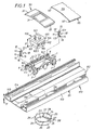
- figure 1 it is a question, globally, of carrying out the recessed implantation of an electrical apparatus 100, on a wiring conduit 110 with a complete embedding of the apparatus 100 in the conduit 110, the apparatus flush, in frontage, the leads.
- the electrical apparatus 100 shown in the figures is a conventional socket whose constitution, known in itself, and not specifically part of the present invention, will not be described in detail. It is sufficient to mention here that the apparatus 100 comprises, in the usual manner, a parallelepiped body 101 provided on two of its opposite lateral faces of teeth 102 and having a useful front face 103 on which the interface means with the outside ( in this case, the insertion holes of the pins of a corresponding male plug) are accessible.
- a flange 105 adjacent to the useful front face 103 forms, towards the rear, a shoulder 104 which delimits with the teeth 102 a groove 106 on each of the corresponding lateral faces of the body 101, this groove serving to fix the apparatus 100 as will be better explained later.
- the overall depth of this apparatus was noted P
- the wiring duct 110 mainly comprises a base 111 which is generally in the form of a profile, for example an extruded plastic or metal material such as spun aluminum or steel formed.
- This base 111 has a flat bottom 112 and two longitudinal wings 113 formed by lateral returns at right angles to the bottom 112.
- the two wings 113 have a height p which corresponds substantially to the overall depth of the conduit.
- the overall depth p of the conduit 110 is substantially less than the depth P of the apparatus 100.
- a cover 115 is attached to the base 111 of the duct 110 and is provided for this purpose, on its two lateral edges, with two longitudinal beads 117 adapted to engage in two longitudinal grooves 114 corresponding formed at the top of the wings 113 of the base 111 .
- the bottom 112 of the base 111 is provided on its inner face or front, two blades 118, which, inclined towards one another form rails or rails intended to cooperate with the device according to the invention.
- These slides 118 are here integral with the rest of the base 111, for example by extrusion. But they could also be reported, for example by welding, riveting, etc.
- This frame 1 is generally rectangular in shape and has a longitudinal direction (along its largest dimension) which, after implantation on the conduit 110, merges with the longitudinal direction of this conduit 110. It has a rectangular central space 2 capable of receiving one or more electrical equipment such as the apparatus 100.
- the central space 2 of the support frame 1 is sized to receive either a single electrical apparatus 100 as illustrated by the Figures 1 to 4 , two electrical devices 100 as illustrated by the figures 5 and 6 .
- the central space 2 of this frame is bordered longitudinally by two edges or cornices 3 crenellated below, that is to say on their rear flank, which constitutes the means for receiving the device or devices 100 on the support frame 1.
- the two crenellated longitudinal edges 3 thus formed internally on the frame 1 form a hard point passage for the teeth 102 fitted to the body 101 of the apparatus 100 to be installed.
- the longitudinal flanges 3 are received in the grooves 106 of the apparatus 100 and immobilize it by being engaged on the one hand by the stop face 102.1 teeth 102 which oppose the extraction of the apparatus 100 and secondly the shoulder 104 which opposes the depression of the apparatus 100.
- the teeth 102 are further received in the slots arranged at the rear of the flanges 3 so as to be immobilized on the frame 1 in its longitudinal direction.
- the support frame 1 further comprises means for its attachment to the base 111 of the conduit 110.
- These fixing means are made in the form of four lateral pads 5, 6 formed at the four corners of the support frame 1 and each provided with a heel or blade 7, 8 arranged to engage with the slides 118 fitted to the bottom 112 of the base 111 of the duct 110.
- the two pads 5 located on the same longitudinal side of the frame 1 and intended to engage with the same slide 118 are relatively rigid, while the other two pads 6 located on the other side of the frame 1 and intended to engage with the other slide 118 have a certain transverse mobility, that is to say in a direction perpendicular to the longitudinal direction of the frame 1 and the conduit 110.
- Each of the two pads 6 is thus movable between a friction lock configuration or clamping on the corresponding slide 118 of the base 111 of the conduit 110, a free sliding configuration on this slide and a configuration of complete release of its grip with this slide, allowing the extraction of the support frame 1.
- the support frame 1 with its receiving flanges 3 and its fixing pads 6, 7, is made in one piece, for example molded plastic or metal material such as Zamak.
- the pads 5, 6 are integral with the rest of the frame 1. Under these conditions, the mobility of the movable pads 6 results from an elastic flexibility own of these pads, with a rest configuration corresponding to the free sliding configuration on the corresponding slide 118, engaged therewith.
- each of the two movable pads 6 in its friction locking or release configurations are obtained by an external action forcing the bending of the movable pad 6 concerned against its own elasticity.
- each mobile pad 6 towards its release configuration can for example be obtained (when it is occasionally desired to disassemble the casing) using a screwdriver-type tool which will exert on said pad a retraction effort towards the interior to disengage the slide 118 concerned.
- each movable pad 6 is subjected to the action of a locking member 10 which is movable between two positrons, one locking maintaining the movable pad 6 concerned in its blocking configuration on the slide 118 and the other unlocking leaving this movable pad 6 free to return to free slide configuration on the slide 118 or complete release of its grip with this slide.
- each of the two locking members 10 is in the form of a cam member mounted on the corner concerned of the frame 1 to pivot about an axis 15 adjacent to the movable pad 6 with which it is associated, between two angular positions constituting its locking and unlocking positions of this movable pad 6.
- This cam element 10 is composed of a pin 11 received for pivoting freely in a shaft or bearing 9 formed on the support frame 1, at the corner corresponding thereof, a head 12 disposed at one of the two ends of the trunnion 11 and on which is formed a recess 12.1 providing a grip for the corresponding head of a screwdriver-type tool, and a shoe 13 disposed at the other end of the pin 11.
- the shoe 13 has a generally parallelepipedal shape, elongated transversely to the pivot axis 15 of the pin 11 in the well 9 and blunted at its angles.
- the shoe 13 comes, by its blunt tip 16, in contact with the inner face of the movable pad 6 concerned and slides against it to push in the manner of a cam, the movable pad 6 concerned outwardly, in tight support against the corresponding slide 118 of the base 111 of the conduit 110.
- the shoe 13 of the cam element 10 is provided, in relief from its face from above, with a boss 14 adapted to be received in a cavity (not visible in the figures) formed on a corresponding part of the support frame 1 for temporarily immobilizing the cam member 10 in the locking position. More specifically, this boss 14 receiving impression is formed in a lower end shoulder 9.1 of the receiving well 9, while the head 12 of the cam member 10 abuts against an upper end shoulder 9.2 of the well 9, so that the top of the shoe 13 of the cam member 10 is urged against the well shoulder 9.1 of the well 9 by means of a slight elastic deformation of the entire cam element 10.
- the trunnion 11 of the cam member 10 has a generally uniform cross section section.
- the cam member 10 with its pin 11, its head 12 and its shoe 13 may advantageously be made in one piece of molded plastic material.
- the bearing or well 9, with its two shoulders 9.1, 9.2 is preferably also integral with the rest of the support frame 1.
- the receiving flange 3 and the fixing pads 5, 6 are arranged in such a way that the front face 103 of the apparatus 100 is flush with the front face 116 of the cover 115 of the duct 110.
- the cover 115 is cut on either side of the implantation zone of the apparatus 100 in the conduit 110.
- the opening thus left by this localized interruption of the cover 115 of the duct 110 is closed by means of a perforated cover or plastron 30 which thus locally replaces the missing portion of the cover 115, as is better visible in the figure 4 .
- This plastron 30 has an aperture 31 of shape and dimension adapted to the outer contour of the front face 103 of the apparatus 100, so as to allow direct access to this face.
- the useful front face 103 of the apparatus 100 is thus flush with the front face 32 of the front plate 30 or extends slightly back from this front face 32.
- the plastron 30 For its fixing on the base 111 of the duct 110, the plastron 30 is provided, like the cover 115 of the duct 110, longitudinal beads 33 formed along its lateral edges to engage in the longitudinal grooves 114 of the base 111 of the conduit 110. It could be expected, however, that the plastron 30 is provided with other means for its attachment to the support frame 1, in addition or alternatively to the beads 114 for its attachment to the base 111 of the duct 110.
- the plastron 30 may be joined to the cover 115 or cover the edges thereof. In this way, the plastron 30 ensures the continuity of the cover 115 of the conduit 110 while allowing access to the useful front face 103 of the apparatus 100 which is flush with the front faces 32 and 116 of the plastron 30 and the cover 115.
- the cover 115 on the base 111 relative to the frame 1 is provided on the one hand with abutments 17 arranged projecting from the longitudinal branches of the frame 1 to delimit a truncation of the cover 115 capable of disengaging access to a single apparatus 100 of restricted size (single-station implantation) as illustrated by the figures 1 and 4 and on the other hand marks 18 arranged on the transverse branches of the frame 1 to visually delimit a truncation of the wider cover capable of providing access for double and / or larger equipment (multi-station implantation), as illustrated by the figures 5 and 6 .
- the device according to the invention further comprises a reservation pot 20 arranged so through an opening 119 formed in correspondence in the bottom 112 of the base 111 of the duct 110 and forming in this bottom 112 a recess for receiving the rear part of the apparatus 100 which extends beyond the duct 110.
- the reservation pot 20 is, in accordance with an essential feature of the invention, made in the form of an entirely separate part and separated from the support frame 1 and has its own fixing means on the base 111 of the duct 110.
- the reservation pot 20 comprises a cylindrical lateral envelope 21 whose rear edge 22 is closed by a bottom 23 solid and preferably flat, and whose front edge 24 is open.
- the opening 119 formed in the bottom 112 of the base 111 of the conduit 110 has a circular contour of substantially the same diameter.
- Means for fixing the reservation pot 20 on the base 111 of the conduit 110 are formed on the open edge 24 of the pot 20. These fixing means comprise two parts, one of support, the other of locking.
- the bearing portion of the locking means is formed by rigid support lugs 25 formed radially outer projection on the open front edge 24 of the casing 21 to bear against the inner face (front face) of the bottom 112 of the
- some of the tabs 25 may be elongate and provided with holes for the passage of screws or rivets which can serve to reinforce the fixing by the fingers 26.
- the locking portion of the fastening means comprises four locking fingers 26 formed on the open front edge 24 of the casing 21 and projecting outwardly in a common direction which, in situ, coincides with the longitudinal direction of the duct. 110. These locking fingers 26 are arranged to cross, by means of a radial elastic contraction of the cylindrical casing 21 of the reservation pot 20, the slides 118 of the base 111 of the duct 110 and thus come into engagement under these slides after the envelope 21 has spontaneously resumed its rest position.
- the device according to the invention is used for fixing a single electrical equipment 100.
- the reservation pot 20 is therefore associated individually, in combination with the support frame 1, this single device.
- the support frame 1 is dimensioned to receive indifferently one or two devices 100.
- the support frame 1 When, as in the case illustrated by the figures 5 and 6 the support frame 1 receives two apparatus 100, there is the problem of the reception of the rear part of these two apparatus 100 by the reservation pot 20 whose radial dimension limits the capacity to a single apparatus.
- the reservation pot 20 has a breaking initiation line 27 extending on the cylindrical envelope 21 and the bottom 23 to allow the detachment of a lateral portion 28 of the reservation pot 20.
- This breaking initiation line 27 extends in a plane which is parallel to the axis of the cylindrical envelope 21, but which does not contain this axis.
- a lateral cutting edge which, designated by the same reference 27, defines a lateral opening through which two adjacent reservoirs 20 contiguous by their respective cutting edges 27 can be joined together, as shown in FIGS. figures 5 and 6 .
- the pairing thus obtained of two reservation pots 20 makes it possible to obtain a double reservation pot able to receive the rear parts of the two apparatuses 100 received on the support frame 1.
- the circular opening 119 formed in the bottom 112 of the base 111 of the conduit 110 will be replicated a number of times corresponding to the number of reservoirs 20 thus associated, with between each opening a offset corresponding to the distance between two consecutive pots. It should be noted in this connection that the fact of using a single modular pot 20 offers the additional advantage of requiring, for the realization of the openings 119 in the bottom 112 of the base 111, only one tool making a single type of tool. opening approximately the same diameter as that of the reservation pot 20.
- the opening obtained with this tool must simply be replicated as many times as necessary, with the desired offset, less than the diameter of the opening 119, to achieve an opening overall dimension of greater dimension and shape perfectly adapted to that of the contour of the overall modular pot obtained by the combination of a series of unitary pots 20.
Landscapes
- Engineering & Computer Science (AREA)
- Architecture (AREA)
- Civil Engineering (AREA)
- Structural Engineering (AREA)
- Installation Of Indoor Wiring (AREA)
- Supports For Pipes And Cables (AREA)
- Details Of Indoor Wiring (AREA)
Claims (20)
- Vorrichtung für Unterputzeinbau wenigstens eines elektrischen Installationsgerätes (100) in einem Installationskanal (110) mit einer Tiefe (p), die geringer ist als die Tiefe (P) des Installationsgerätes, mit:- wenigstens einem Träger (1), der versehen ist mit Mitteln zu seiner Befestigung im Installationskanal und mit Mitteln (3) zur Aufnahme des elektrischen Installationsgerätes (100), die so angeordnet sind, dass die Vorderseite (103) des Installationsgerätes mit der Vorderseite (32, 116) des Kanals (110) durch eine in Übereinstimmung mit dieser ausgebildeten Öffnung (31) hindurch bündig ist, und- wenigstens einer Gerätedose (20), die so angeordnet ist, dass sie eine Öffnung (119) durchquert, die in Übereinstimmung hierzu im Boden (112) des Kanals ausgebildet ist, und in diesem eine Vertiefung zur Aufnahme des hinteren Teils des Installationsgerätes (100) bildet,dadurch gekennzeichnet, dass die Gerätedose (20) in Form eines vom Träger getrennten Teils ausgeführt ist, das über eigene Mittel (25, 26) zur Befestigung am Kanal (110) verfügt.
- Vorrichtung nach Anspruch 1,
mit einerseits einem einzigen Träger (1), dessen Aufnahmemittel (3) zur Aufnahme mehrerer Installationsgeräte (100) vorgesehen sind, und andererseits einer Vielzahl von Gerätedosen (20), die jeweils einem der Installationsgeräte zugeordnet sind. - Vorrichtung nach einem der vorhergehenden Ansprüche,
mit wenigstens zwei Gerätedosen (20), die jeweils eine Ausbruchlinie (27) aufweisen, die so angeordnet ist, dass das Abtrennen eines seitlichen Stücks (28) der Gerätedose (20) entlang eines seitlichen Schnittrands (27) möglich ist, der eine seitliche Öffnung begrenzt, durch die zwei nebeneinanderliegende Gerätedosen (20), die mit ihren jeweiligen seitlichen Schnitträndern (27) aneinanderstoßen, miteinander verbunden werden können. - Vorrichtung nach Anspruch 3,
bei der die Ausbruchlinie (27), da jede Gerätedose (20) eine seitliche Ummantelung (21) mit allgemein zylindrischer Form besitzt, in einer Ebene verläuft, die zur Achse der zylindrischen Ummantelung (21) parallel ist, die jedoch diese Achse nicht enthält. - Vorrichtung nach Anspruch 4,
bei der jede Gerätedose zwei zueinander symmetrische Ausbruchlinien beidseits der Achse der zylindrischen Ummantelung aufweist. - Vorrichtung nach einem der vorhergehenden Ansprüche,
bei der die Mittel zum Befestigen des Trägers (1) auf dem Kanal (110) wenigstens zwei seitliche Gleitschuhe (5, 6) umfassen, die so angeordnet sind, dass sie mit zwei zugeordneten Gleitschienen (118) in Eingriff gelangen, die längs am Boden (112) des Kanals (110) ausgebildet sind. - Vorrichtung nach Anspruch 6,
bei der wenigstens einer (6) der seitlichen Gleitschuhe zum Befestigen des Trägers zwischen einer Arretierstellung durch Reibung auf der entsprechenden Gleitschiene (118) des Kanals (110), einer freien Gleitstellung auf der Gleitschiene und einer vollständigen Freigabestellung aus dem Eingriff mit der Gleitschiene seitlich beweglich ist. - Vorrichtung nach Anspruch 7,
bei der der bewegliche Gleitschuh (6) durch ein Verriegelungsorgan (10) betätigt wird, das zwischen zwei Positionen beweglich ist, einer Verriegelungsposition, die den beweglichen Gleitschuh (6) in seiner Arretierstellung auf der Gleitschiene (118) hält, und einer Entriegelungsposition, in der der bewegliche Gleitschuh (6) wieder die freie Gleitstellung auf der Gleitschiene (118) oder die vollständige Freigabestellung aus dem Eingriff mit der Gleitschiene (118) einnehmen kann. - Vorrichtung nach Anspruch 8,
bei der das Organ zur Verriegelung des beweglichen Gleitschuhs (6) ein Nockenelement (10) umfasst, das auf dem Träger (1) schwenkbar montiert ist und zu seiner Schwenkbetätigung zwischen zwei Winkelstellungen in einen beliebigen Eingriff (12.1) gelangt, die seine vorstehend genannte Verriegelungsposition und Entriegelungsposition bilden. - Vorrichtung nach Anspruch 9,
bei der die zwei Winkelstellungen des Nockenelements durch eine Vierteldrehung getrennt sind. - Vorrichtung nach Anspruch 10,
bei der das Nockenelement (10) aus einem Drehzapfen (11), der zum freien Schwenken in einem am Träger (1) ausgebildeten Schacht oder Lager (9) aufgenommen ist, einem Kopf (12), der an einem der beiden Enden des Drehzapfens (11) angeordnet ist und auf dem eine Vertiefung zur Betätigung (12.1) ausgebildet ist, die zum Zusammenwirken mit einem Werkzeug vom Typ Schraubenzieher bestimmt ist, und einem Schuh (13) besteht, der an dem anderen Ende des Drehzapfens (11) angeordnet ist und eine allgemein parallelepipedische längliche Form quer zur Schwenkachse (15) des Drehzapfens (11) aufweist. - Vorrichtung nach Anspruch 11,
bei der der Schuh (13) des Nockenelements (10) mit einer Vorwölbung (14) versehen ist, die in einer Vertiefung aufgenommen zu werden vermag, die auf einem entsprechenden Teil des Trägers (1) ausgebildet ist, um das Nockenelement (10) vorübergehend in der Verriegelungsposition zu blockieren. - Vorrichtung nach Anspruch 12,
bei der die Vorwölbung (14) des Schuhs (13) des Nockenelements (10) auf der Oberseite des Schuhs ausgebildet ist, während die Vertiefung zur Aufnahme der Vorwölbung in einem ersten äußeren hinteren Absatz (9.1) des Schachts (9) zur Aufnahme des Drehzapfens des Nockenelements (10) ausgebildet ist, wobei der Kopf (12) des Nockenelements gegen einen äußeren vorderen Absatz (9.2) des Schachts solchermaßen in Anschlag ist, dass die Oberseite des Schuhs (13) des Nockenelements (10) gegen den äußeren hinteren Absatz (9.1) des Schachts mit Hilfe einer geringen elastischen Verformung des gesamten Nockenelements (10) wieder in dichten Anschlag gelangt. - Vorrichtung nach Anspruch 12,
bei der die Vorwölbung (14) des Schuhs des Nockenelements (10) an der Spitze (16) des Schuhs ausgebildet ist, während die Vertiefung zur Aufnahme der Vorwölbung in dem beweglichen Gleitschuh (6) im rechten Winkel zur Schwenkachse (15) des Nockenelements (10) ausgebildet ist. - Vorrichtung nach einem der Ansprüche 11 bis 14,
bei der der Drehzapfen (11) des Nockenelements (10) allgemein eine Profilform mit kreuzförmigem Querschnitt aufweist. - Vorrichtung nach einem der Ansprüche 12 bis 15,
bei der das Nockenelement (10) mit seinem Drehzapfen (11), seinem Kopf (12) und seinem Schuh (13) in einem Stück aus formgegossenem Kunststoff ausgeführt ist. - Vorrichtung nach einem der Ansprüche 4 bis 16,
bei der der Träger (1) in einem Stück aus formgegossenem Kunststoff mit seinen seitlichen Befestigungsgleitschuhen (5, 6) ausgeführt ist. - Vorrichtung nach Anspruch 17,
bei der die Beweglichkeit des beweglichen Gleitschuhs (6) aus einer elastischen Biegbarkeit des Gleitschuhs resultiert, mit einer Ruhestellung, die der freien Gleitstellung auf der entsprechenden Gleitschiene (118) des Kanals (110) in Eingriff mit dieser entspricht. - Vorrichtung nach einem der vorhergehenden Ansprüche,
bei der die Mittel zur Befestigung der Gerätedose (20) am Kanal starre Abstützlaschen (25) aufweisen, die radial nach außen vorstehend am vorderen offenen Rand (24) der Gerätedose (20) ausgebildet sind, um am Boden (112) des Kanals (110) aufzuliegen. - Vorrichtung nach Anspruch 19,
bei der die Mittel zur Befestigung der Gerätedose am Kanal wenigstens zwei Verriegelungszapfen (26) umfassen, die am offen oberen Rand der Gerätedose ausgebildet sind, um nach radialer Verformung der Dose nach außen in Eingriff mit der entsprechenden Gleitschiene (118) des Bodens (112) des Kanals (110) zu gelangen.
Applications Claiming Priority (2)
| Application Number | Priority Date | Filing Date | Title |
|---|---|---|---|
| FR0011798A FR2814293B1 (fr) | 2000-09-15 | 2000-09-15 | Dispositif pour l'implantation encastree d'au moins un appareillage electrique dans un conduit de cablage de profondeur inferieure a celle de l'appareillage |
| FR0011798 | 2000-09-15 |
Publications (2)
| Publication Number | Publication Date |
|---|---|
| EP1189323A1 EP1189323A1 (de) | 2002-03-20 |
| EP1189323B1 true EP1189323B1 (de) | 2011-02-09 |
Family
ID=8854348
Family Applications (1)
| Application Number | Title | Priority Date | Filing Date |
|---|---|---|---|
| EP01402248A Expired - Lifetime EP1189323B1 (de) | 2000-09-15 | 2001-08-29 | Vorrichtung zur Befestigung eines eingebauten elektrischen Gerätes in einen Kabelkanal mit einer kleineren Tiefe |
Country Status (6)
| Country | Link |
|---|---|
| US (1) | US6576834B2 (de) |
| EP (1) | EP1189323B1 (de) |
| CA (1) | CA2357319A1 (de) |
| DE (1) | DE60144002D1 (de) |
| ES (1) | ES2360931T3 (de) |
| FR (1) | FR2814293B1 (de) |
Families Citing this family (14)
| Publication number | Priority date | Publication date | Assignee | Title |
|---|---|---|---|---|
| US6972367B2 (en) * | 2001-10-31 | 2005-12-06 | Hellermanntyton Corporation | Multi-channel raceway |
| DE10223840B4 (de) * | 2002-05-28 | 2004-04-29 | Airbus Deutschland Gmbh | Kanal-Anordnung |
| US6881083B2 (en) * | 2002-07-19 | 2005-04-19 | The Wiremold Company | Raceway system with selectively placed outlet devices |
| US6700060B1 (en) * | 2002-08-29 | 2004-03-02 | Eaton Corporation | Auxiliary wiring trough |
| US7112748B2 (en) * | 2004-01-09 | 2006-09-26 | Panduit Corp. | Hanging box and faceplate adapter |
| US7408114B2 (en) * | 2005-08-23 | 2008-08-05 | Panduit Corp. | Metal raceway system |
| US7829797B2 (en) * | 2005-10-17 | 2010-11-09 | Panduit Corp. | Three channel raceway |
| FR2930684B1 (fr) * | 2008-04-29 | 2010-05-21 | Inovac | Accessoire de montage d'un bloc electrique dans un conduit de cheminement de cables ou de conducteurs electriques et ensemble electrique comprenant un bloc electrique ainsi qu'un tel accessoire |
| AR066673A1 (es) * | 2008-05-22 | 2009-09-02 | De Olano Luis Alberto Ruiz | Modulo de interconexion |
| US8881469B1 (en) | 2010-11-18 | 2014-11-11 | Consolidated Systems, Inc. | Cellular ceiling deck system with hidden hinges |
| CN103075515B (zh) * | 2012-12-25 | 2015-08-12 | 王奉瑾 | 用于箱体间的密封定位台 |
| EP3059825B1 (de) * | 2015-02-18 | 2018-02-14 | Pucci Saoro, S.R.L. | Rahmen für unterputzdosen und kit für eine solche halterung für elektrische oder automatisierte hauskomponenten |
| GB2551713B (en) * | 2016-06-27 | 2020-02-26 | Bombardier Transp Gmbh | Cable tray assembly for a vehicle body of a rail vehicle and its method of assembly |
| CH713749B1 (de) * | 2017-04-21 | 2019-02-28 | E Intec Gmbh | Aggregat für elektrotechnische Funktionen. |
Family Cites Families (15)
| Publication number | Priority date | Publication date | Assignee | Title |
|---|---|---|---|---|
| US3592956A (en) * | 1969-05-07 | 1971-07-13 | Robertson Co H H | Electrical raceway wiring distribution system |
| US3932696A (en) * | 1973-12-26 | 1976-01-13 | H. H. Robertson Company | Underfloor access housing utilizing a trough space of a cellular flooring unit |
| US4178469A (en) * | 1978-07-21 | 1979-12-11 | H. H. Robertson Company | Closure device and floor structure utilizing the same |
| US4443654A (en) * | 1981-10-19 | 1984-04-17 | Butler Manufacturing Company | Flush floor fitting |
| US4558546A (en) * | 1983-01-20 | 1985-12-17 | Robert Nusbaum | Underfloor assembly and cable distribution system and cable trench therefor |
| US5010211A (en) * | 1989-06-29 | 1991-04-23 | Square D Company | Flushing floor fitting |
| FR2658009B1 (fr) * | 1990-02-02 | 1992-05-22 | Legrand Sa | Boite d'encastrement a prolongement lateral, notamment pour appareil electrique. |
| ES2065275B1 (es) * | 1993-06-14 | 1996-08-16 | Aparellaje Electrico Sa | Dispositivo de soporte de mecanismos electricos en canaletas para conducciones electricas. |
| BE1008718A3 (nl) * | 1994-09-13 | 1996-07-02 | Jvk Plastics Nv | Inbouwdoos voor elektrisch installatiemateriaal, samenstel van inbouwdozen en daarbij gebruikte afstandhouder en spruitstuk. |
| FR2729255A1 (fr) * | 1995-01-05 | 1996-07-12 | Planet Wattohm Snc | Support d'appareillage a boite semi-encastree a travers un conduit, et son procede de mise en oeuvre |
| US5942724A (en) * | 1997-09-23 | 1999-08-24 | The Wiremold Company | Wire containment system for mounting on a wall structure |
| US6072121A (en) * | 1998-12-14 | 2000-06-06 | Walker Systems, Inc. | Preset insert housing for underfloor raceways |
| US6211460B1 (en) * | 1998-12-16 | 2001-04-03 | The Lamson & Sessions Co. | Multi-device yoke for a surface raceway system |
| US6350135B1 (en) * | 1999-07-29 | 2002-02-26 | University Of Rochester | Power outlet for divided channel raceway |
| US6335485B1 (en) * | 1999-11-24 | 2002-01-01 | Aparellaje Electrico, S.A. | Box for the installation of electrical apparatus in a raceway for electrical cables |
-
2000
- 2000-09-15 FR FR0011798A patent/FR2814293B1/fr not_active Expired - Lifetime
-
2001
- 2001-08-29 DE DE60144002T patent/DE60144002D1/de not_active Expired - Lifetime
- 2001-08-29 EP EP01402248A patent/EP1189323B1/de not_active Expired - Lifetime
- 2001-08-29 ES ES01402248T patent/ES2360931T3/es not_active Expired - Lifetime
- 2001-09-14 US US09/951,636 patent/US6576834B2/en not_active Expired - Fee Related
- 2001-09-14 CA CA002357319A patent/CA2357319A1/fr not_active Abandoned
Also Published As
| Publication number | Publication date |
|---|---|
| EP1189323A1 (de) | 2002-03-20 |
| FR2814293A1 (fr) | 2002-03-22 |
| DE60144002D1 (de) | 2011-03-24 |
| US20020033268A1 (en) | 2002-03-21 |
| CA2357319A1 (fr) | 2002-03-15 |
| ES2360931T3 (es) | 2011-06-10 |
| US6576834B2 (en) | 2003-06-10 |
| FR2814293B1 (fr) | 2002-11-29 |
Similar Documents
| Publication | Publication Date | Title |
|---|---|---|
| EP1189323B1 (de) | Vorrichtung zur Befestigung eines eingebauten elektrischen Gerätes in einen Kabelkanal mit einer kleineren Tiefe | |
| FR3000308A1 (fr) | Module d'appareillage electrique amovible, boite electrique d'accueil d'un tel module d'appareillage et procede de remplacement d'un tel module d'appareillage | |
| EP2143846B1 (de) | Unterputzdose für Sanitärinstallationen | |
| FR2903707A1 (fr) | Element de fixation pour lame de couverture de surface et lame de couverture de surface adaptee a un tel element de fixation | |
| CA3032086A1 (fr) | Caisson de meuble | |
| EP3138166B1 (de) | Elektromodul zum einschnappen in eine elektrodose | |
| EP1213811B1 (de) | Modulare Dose zum versenkten Einbau von einem Gerät oder mehrerer Geräte in einen Kabelkanal mit einer kleineren Tiefe und mit mindestens zwei Dosen hergestelltes Gehäuse | |
| EP1744427B1 (de) | Gehäuse eines elektrischen Gerätes mit verstellbarer Tiefe | |
| EP1164676B1 (de) | Vorrichtung zur Befestigung eines elektrischen Geräts auf einem Kabelkanal | |
| EP0706252B1 (de) | Geräteträger anzubringen auf einer Einbaudose und Befestigungsteil zum Gebrauch mit solchem Geräteträger | |
| EP1744426B1 (de) | Elektrischer Kasten bestehend aus zwei Elemente die mit einer Zahnstange zusammen befestigt sind | |
| EP0923176B1 (de) | Greifhalter für Einbaudose und entsprechende Einbaudose | |
| FR2856202A1 (fr) | Support d'appareillage electrique et accessoire pour sa fixation par vis | |
| EP1170844A1 (de) | Einrichtung zum halbversenkten Einbau von mindestens einem Gerät in einen Kabelkanal mit einer kleineren Tiefe | |
| FR3043853A1 (fr) | Bague de reception d'une boite electrique a encastrer dans une paroi murale | |
| EP2068411A1 (de) | Elektrische Einbau-Ausrüstung mit Schnellanschluss | |
| BE1005858A3 (fr) | Coffret pour appareils electriques, a habillage exterieur presentant au moins une plaque amovible. | |
| FR2764361A1 (fr) | Double bride pour canalisations de surface | |
| EP1465310A1 (de) | Einbaudose für Trockenwand | |
| EP0887903B1 (de) | Sockel für Kabelkanal mit einem V-förmigen Querschnitt, insbesondere Eckkanal oder Unterputzkanal | |
| WO2017194891A1 (fr) | Appareillage electrique equipe de systemes de fixation a griffes | |
| EP2422416B1 (de) | Höheneinstellbare bodendose | |
| FR2779876A1 (fr) | Accessoire de derivation pour installation electrique, et installation electrique correspondante | |
| FR2973596A1 (fr) | Enveloppe allongee pour appareillages et/ou conducteurs electriques comportant un accessoire d'extremite | |
| FR2877508A1 (fr) | Coffret de branchement pour cables electriques |
Legal Events
| Date | Code | Title | Description |
|---|---|---|---|
| PUAI | Public reference made under article 153(3) epc to a published international application that has entered the european phase |
Free format text: ORIGINAL CODE: 0009012 |
|
| AK | Designated contracting states |
Kind code of ref document: A1 Designated state(s): DE ES GB IT SE Kind code of ref document: A1 Designated state(s): AT BE CH CY DE DK ES FI FR GB GR IE IT LI LU MC NL PT SE TR |
|
| AX | Request for extension of the european patent |
Free format text: AL;LT;LV;MK;RO;SI |
|
| 17P | Request for examination filed |
Effective date: 20020220 |
|
| AKX | Designation fees paid |
Free format text: DE ES GB IT SE |
|
| GRAP | Despatch of communication of intention to grant a patent |
Free format text: ORIGINAL CODE: EPIDOSNIGR1 |
|
| RAP1 | Party data changed (applicant data changed or rights of an application transferred) |
Owner name: PLANET WATTOHM |
|
| GRAS | Grant fee paid |
Free format text: ORIGINAL CODE: EPIDOSNIGR3 |
|
| GRAA | (expected) grant |
Free format text: ORIGINAL CODE: 0009210 |
|
| AK | Designated contracting states |
Kind code of ref document: B1 Designated state(s): DE ES GB IT SE |
|
| REG | Reference to a national code |
Ref country code: GB Ref legal event code: FG4D Free format text: NOT ENGLISH |
|
| REF | Corresponds to: |
Ref document number: 60144002 Country of ref document: DE Date of ref document: 20110324 Kind code of ref document: P |
|
| REG | Reference to a national code |
Ref country code: DE Ref legal event code: R096 Ref document number: 60144002 Country of ref document: DE Effective date: 20110324 |
|
| REG | Reference to a national code |
Ref country code: ES Ref legal event code: FG2A Ref document number: 2360931 Country of ref document: ES Kind code of ref document: T3 Effective date: 20110610 |
|
| PG25 | Lapsed in a contracting state [announced via postgrant information from national office to epo] |
Ref country code: SE Free format text: LAPSE BECAUSE OF FAILURE TO SUBMIT A TRANSLATION OF THE DESCRIPTION OR TO PAY THE FEE WITHIN THE PRESCRIBED TIME-LIMIT Effective date: 20110209 |
|
| PGFP | Annual fee paid to national office [announced via postgrant information from national office to epo] |
Ref country code: GB Payment date: 20110815 Year of fee payment: 11 |
|
| PLBE | No opposition filed within time limit |
Free format text: ORIGINAL CODE: 0009261 |
|
| STAA | Information on the status of an ep patent application or granted ep patent |
Free format text: STATUS: NO OPPOSITION FILED WITHIN TIME LIMIT |
|
| 26N | No opposition filed |
Effective date: 20111110 |
|
| REG | Reference to a national code |
Ref country code: DE Ref legal event code: R097 Ref document number: 60144002 Country of ref document: DE Effective date: 20111110 |
|
| GBPC | Gb: european patent ceased through non-payment of renewal fee |
Effective date: 20120829 |
|
| PG25 | Lapsed in a contracting state [announced via postgrant information from national office to epo] |
Ref country code: GB Free format text: LAPSE BECAUSE OF NON-PAYMENT OF DUE FEES Effective date: 20120829 |
|
| PGFP | Annual fee paid to national office [announced via postgrant information from national office to epo] |
Ref country code: ES Payment date: 20130724 Year of fee payment: 13 |
|
| REG | Reference to a national code |
Ref country code: ES Ref legal event code: FD2A Effective date: 20150928 |
|
| PG25 | Lapsed in a contracting state [announced via postgrant information from national office to epo] |
Ref country code: ES Free format text: LAPSE BECAUSE OF NON-PAYMENT OF DUE FEES Effective date: 20140830 |
|
| PGFP | Annual fee paid to national office [announced via postgrant information from national office to epo] |
Ref country code: IT Payment date: 20160818 Year of fee payment: 16 |
|
| PGFP | Annual fee paid to national office [announced via postgrant information from national office to epo] |
Ref country code: DE Payment date: 20170829 Year of fee payment: 17 |
|
| PG25 | Lapsed in a contracting state [announced via postgrant information from national office to epo] |
Ref country code: IT Free format text: LAPSE BECAUSE OF NON-PAYMENT OF DUE FEES Effective date: 20170829 |
|
| REG | Reference to a national code |
Ref country code: DE Ref legal event code: R119 Ref document number: 60144002 Country of ref document: DE |
|
| PG25 | Lapsed in a contracting state [announced via postgrant information from national office to epo] |
Ref country code: DE Free format text: LAPSE BECAUSE OF NON-PAYMENT OF DUE FEES Effective date: 20190301 |