EP1189784B1 - Neigungsverstellbeschlag für die rückenlehne eines kraftfahrzeugsitzes - Google Patents
Neigungsverstellbeschlag für die rückenlehne eines kraftfahrzeugsitzes Download PDFInfo
- Publication number
- EP1189784B1 EP1189784B1 EP01911672A EP01911672A EP1189784B1 EP 1189784 B1 EP1189784 B1 EP 1189784B1 EP 01911672 A EP01911672 A EP 01911672A EP 01911672 A EP01911672 A EP 01911672A EP 1189784 B1 EP1189784 B1 EP 1189784B1
- Authority
- EP
- European Patent Office
- Prior art keywords
- fitment
- backrest
- area
- incline adjustment
- polygonal
- Prior art date
- Legal status (The legal status is an assumption and is not a legal conclusion. Google has not performed a legal analysis and makes no representation as to the accuracy of the status listed.)
- Expired - Lifetime
Links
- 230000000295 complement effect Effects 0.000 claims description 2
- 230000002093 peripheral effect Effects 0.000 description 5
- 238000005096 rolling process Methods 0.000 description 2
- 238000010276 construction Methods 0.000 description 1
- 230000014509 gene expression Effects 0.000 description 1
Images





Classifications
-
- B—PERFORMING OPERATIONS; TRANSPORTING
- B60—VEHICLES IN GENERAL
- B60N—SEATS SPECIALLY ADAPTED FOR VEHICLES; VEHICLE PASSENGER ACCOMMODATION NOT OTHERWISE PROVIDED FOR
- B60N2/00—Seats specially adapted for vehicles; Arrangement or mounting of seats in vehicles
- B60N2/02—Seats specially adapted for vehicles; Arrangement or mounting of seats in vehicles the seat or part thereof being movable, e.g. adjustable
- B60N2/22—Seats specially adapted for vehicles; Arrangement or mounting of seats in vehicles the seat or part thereof being movable, e.g. adjustable the back-rest being adjustable
- B60N2/225—Seats specially adapted for vehicles; Arrangement or mounting of seats in vehicles the seat or part thereof being movable, e.g. adjustable the back-rest being adjustable by cycloidal or planetary mechanisms
- B60N2/2252—Seats specially adapted for vehicles; Arrangement or mounting of seats in vehicles the seat or part thereof being movable, e.g. adjustable the back-rest being adjustable by cycloidal or planetary mechanisms in which the central axis of the gearing lies inside the periphery of an orbital gear, e.g. one gear without sun gear
Definitions
- the invention relates to a tilt adjustment fitting the preamble of claim 1.
- a tilt adjustment fitting that is assumed to be known Art (DE 43 04 725 C2) has two intermeshing teeth of a wobble mechanism engaging fittings on which are inseparable from the flange areas with the Backrest or the seat part are connected.
- To record of large axial forces or moments that occur in the event of a crash are the fitting parts in areas of bracket areas, the fittings in mutual contact hold, encroached on their scope. This safeguard against side loads is insufficient. It was already improved by the fact that an additional, during pivoting radially deviating bracket area is provided is. This additional bracket area can also solve the problem only partially solve.
- the invention is based on this prior art based on the task of a tilt adjustment fitting as a known presupposed kind so that also the intermeshing toothing areas under high loads stay engaged.
- the tilt adjustment fitting according to the invention is also in the Crash in the event that the intermeshing toothing areas do not emerge protected.
- the backrest in spite of the all around closed clamp area with connected to the seat part so that both parts can be replaced at any time can be.
- Welded connections can be dispensed with be without the load capacity of the connection is reduced. Even with one that spans both fittings Locking ring, the torque capacity not reduced by its polygonal circumferential contour.
- a backrest is over a tilt adjustment fitting Giveaway on a seat part.
- One tilt adjustment fitting each is a mirror image arranged on each side of the motor vehicle seat.
- the both tilt adjustment fittings are by a polygonal shaft 6 synchronously adjustable.
- a flange 2 is attached to the backrest, one polygonal, closed receiving opening 2a carries.
- a locking ring 7 axially immovable used one complementary to the receiving opening 2a Has peripheral region 7d. With the outside surfaces of the polygonal peripheral region 7d is the locking ring 7 on counter surfaces 2b of the receiving openings 2a without play.
- the circumferential region 7d is closed by radially inwardly directed annular bracket regions 7a and 7b.
- a first fitting part 4 a radial with matching outer circumference without play in the locking ring 7 has polygonal peripheral region 4b.
- the first fitting part 4 is indicated by polygon surfaces 4c on the peripheral region 4b rotatably in the locking ring 7 and in the receiving opening 2a is included and is therefore fixed to the backrest.
- On the backrest fixed Fitting part 4 are several to the inside of the seat indicative enforcements for riveting a not shown Brake provided.
- the second fitting part 3 has a circular cylindrical Outer circumference 3c and is rotatably held in the locking ring 7.
- the Locking ring 7 After the fitting parts 3 and 4 have been inserted, the Locking ring 7 by rolling the clamp area 7b inwards be closed around the peripheral region 4b.
- the locking ring 7 then has an approximately U-shaped shape in axial section. A possible axial play between the fitting parts 3 and 4 is by expressions 7c in Clamp area 7a eliminated.
- the fitting part 4 fixed to the backrest has, as in FIG. 6 shown, a hub 4e surrounded by a bearing bush 5b is on which an eccentric 5 is rotatably mounted.
- the Eccentric 5 is form-fitting from the polygonal shaft 6 penetrated by a spring washer 10 axially immovable is held in the eccentric 5.
- the toothed ring 3a engages its external toothing 3b into one on the first fitting part 4 provided internal toothing 4a.
- the internal toothing 4a has at least one tooth more than the external toothing 3b and, as can be seen from FIG. 4, a tooth height larger Tip circle diameter than the external teeth 3b.
- the toothed ring 3a protrudes axially beyond the fitting part 4. With the protruding area of the external toothing 3b the toothed ring 3a into an internal toothing visible in FIG Passage 3d pressed into the fitting part 3.
- To the second fitting part 3 are two further passages with polygonal Circumferential areas 3e and 3f pronounced as polygons of different sizes with polygonal surfaces 3g are.
- Several of the polygon surfaces 3g lie on counter surfaces 1b of the seat-fixed flange 1, which has a receiving opening 1a surrounded.
- the receiving opening 1a is through a Cross bar 1c closed.
- the polygon surfaces 3g and Counter surfaces 1b hold the second fitting part 3 in a rotationally fixed manner on the flange fixed to the seat part 1.
- the polygonal shaft 6 becomes axial in the eccentric 5 immovable by arranged on the spring washer 10 Clamping tabs 10a held.
- the clamping lugs 10 spread when Slide on the polygonal shaft 6 and wedge on her.
- the spring washer 10 also has the circumference distributed spring fingers 10b, which adjoin a circumferential Apply inner wall of the eccentric 5 under pretension.
- a rotation of the polygonal shaft 6 with the rotation on it held eccentric 5 leads to a rolling movement of the external toothing 3b of the toothed ring 3a on the internal toothing 4a of the fitting part 4. Due to the different number of teeth shifts the fitting 4 relative to that with the Seat part rotatably connected fitting part 3 in the circumferential direction.
- the backrest with the flange 2 is with everyone Rotation of the polygonal shaft 6 by the tooth pitch and the deviating number of teeth pivots given angle.
Landscapes
- Engineering & Computer Science (AREA)
- Aviation & Aerospace Engineering (AREA)
- Transportation (AREA)
- Mechanical Engineering (AREA)
- Chairs For Special Purposes, Such As Reclining Chairs (AREA)
- Seats For Vehicles (AREA)
Description
- Figur 1 -
- eine perspektivische Explosionsdarstellung eines Neigungsverstellbeschlags mit Blickrichtung von der Außenseite;
- Figur 2 -
- eine Explosionsdarstellung des Neigungsverstellbeschlags nach Fig. 1 mit Blickrichtung von der Innenseite;
- Figur 3 -
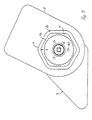
- eine Seitenansicht des Neigungsverstellbeschlags nach Fig. 1 von außen;
- Figur 4 -
- einen Schnitt entlang der Schnittebene IV - IV in Fig. 3;
- Figur 5 -
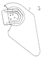
- eine Seitenansicht des Neigungsverstellbeschlags nach Fig. 1 von innen;
- Figur 6 -
- eine vergrößerte, perspektivische Darstellung des Beschlagteils mit Innenverzahnung nach Fig. 1;
- Figur 7 -
- eine vergrößerte perspektivische Darstellung des Schließrings nach Fig. 1;
- Figur 8 -
- eine vergrößerte perspektivische Darstellung des sitzteilfesten Flanschteils nach Fig. 1;
- Figur 9 -
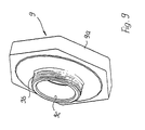
- eine vergrößerte perspektivische Darstellung des Gewinderings nach Fig. 1;
- Figur 10 -
- eine vergrößerte perspektivische Darstellung der Federscheibe nach Fig. 1;
- Figur 11 -
- eine Stirnansicht der Federscheibe nach Fig. 10.
Claims (11)
- Neigungsverstellbeschlag für die Rückenlehne eines Kraftfahrzeugsitzes, bei dem ein am sitz befestigbares Beschlagteil (3) und ein an der Rückenlehne befestigbares und gemeinsam mit ihr schwenkbares Beschlagteil (4) über einen drehbaren Exzenter (5) miteinander verbunden sind und ein erstes Beschlagteil (4) eine Innenverzahnung (4a) aufweist, an der eine einen Teil eines Taumelgetriebes bildende Außenverzahnung (3b) des zweiten Beschlagteils (3) abläuft, wobei das erste und das zweite Beschlagteil (4; 3) übergreifende Klammerbereiche (7a; 7b) vorgesehen sind,
dadurch gekennzeichnet, daß mindestens eines der Beschlagteile (3; 4) einen polygonalen Umfangsbereich (3e; 3f; 4b) aufweist, der in einer Aufnahmeöffnung (1a; 2a) an der Rückenlehne oder dem Sitzteil mit an mehreren Polygonflächen (3g; 4c) des Umfangsbereichs (3e; 3f; 4b) anliegenden Gegenflächen (1b; 2b) drehfest aufnehmbar ist und dessen Außenumfang von einem ringsum geschlossen verlaufenden Klammerbereich (7a; 7b) übergriffen wird. - Neigungsverstellbeschlag nach Anspruch 1,
dadurch gekennzeichnet, daß mindestens die eine von zwei Aufnahmeöffnungen (1a; 2a) ringsum geschlossen ausgebildet ist. - Neigungsverstellbeschlag nach Anspruch 1 oder 2,
dadurch gekennzeichnet, daß die Klammerbereiche (7a; 7b) an einem polygonal ausgebildeten Schließring (7) angeordnet sind, der den Außenumfang des ersten und des zweiten Beschlagteils (4; 3) übergreift. - Neigungsverstellbeschlag nach Anspruch 3,
dadurch gekennzeichnet, daß der Schließring (7) im Querschnittsprofil annähernd U-förmig ausgebildet ist. - Neigungsverstellbeschlag nach einem oder mehreren der Ansprüche 1 bis 4,
dadurch gekennzeichnet, daß der Schließring (7) zur Aufnahme der Beschlagteile (3; 4) mit geschlossen umlaufender Klammerung einen gerollten Klammerbereich (7a; 7b) aufweist. - Neigungsverstellbeschlag nach einem oder mehreren der Ansprüche 1 bis 5,
dadurch gekennzeichnet, daß der Schließring (7) in einem Klammerbereich (7a) axial vorstehende, spielbeseitigende Ausprägungen (7c) aufweist. - Neigungsverstellbeschlag nach einem oder mehreren der Ansprüche 1 bis 6,
dadurch gekennzeichnet, daß mindestens ei in einer polygonalen Aufnahmeöffnung (1a) drehfest aufnehmbares Beschlagteil (3) mit dem die Aufnahmeöffnung (1a) aufweisenden Rückenlehnen- oder Sitzteilbereich axial verschraubbar ist. - Neigungsverstellbeschlag nach Anspruch 7,
dadurch gekennzeichnet, daß das Beschlagteil (3) zentral von einer einen Bund (8a) aufweisenden Gewindebuchse (8) durchsetzt wird, die mit einem das Beschlagteil (3) axial unverschieblich an den die Aufnahmeöffnung (1a) aufweisenden Sitzteil- oder Rückenlehnenbereich anpressenden Gewindering (9) verschraubt ist. - Neigungsverstellbeschlag nach einem oder mehreren der Ansprüche 1 bis 8,
dadurch gekennzeichnet, daß der Gewindering (9) und die Gewindebuchse (8) von einer Mehrkantwelle (6) durchsetzt wird, auf der der Exzenter (5) drehfest gelagert ist. - Neigungsverstellbeschlag nach einem oder mehreren der Ansprüche 1 bis 9,
dadurch gekennzeichnet, daß das die Außenverzahnung tragende Beschlagteil (3) einen innenverzahnten Durchzug (3d) aufweist, in den ein eine in die Innenverzahnung (4a) des anderen Beschlagteils (4) eingreifende Außenverzahnung (3b) tragender Zahnring (3a) eingepreßt ist. - Neigungsverstellbeschlag nach einem oder mehreren der Ansprüche 1 bis 10,
dadurch gekennzeichnet, daß ein Beschlagteil (3) mehrere Durchzüge mit polygonal geformten Umfangsbereichen (3e; 3f) aufweist, die in die komplementär gestufte Aufnahmeöffnung (1a) unverdrehbar einsetzbar sind.
Applications Claiming Priority (3)
| Application Number | Priority Date | Filing Date | Title |
|---|---|---|---|
| DE10021403A DE10021403C2 (de) | 2000-05-03 | 2000-05-03 | Neigungsverstellbeschlag für die Rückenlehne eines Kraftfahrzeugsitzes |
| DE10021403 | 2000-05-03 | ||
| PCT/EP2001/001945 WO2001083259A1 (de) | 2000-05-03 | 2001-02-21 | Neigungsverstellbeschlag für die rückenlehne eines kraftfahrzeugsitzes |
Publications (2)
| Publication Number | Publication Date |
|---|---|
| EP1189784A1 EP1189784A1 (de) | 2002-03-27 |
| EP1189784B1 true EP1189784B1 (de) | 2003-08-13 |
Family
ID=7640564
Family Applications (1)
| Application Number | Title | Priority Date | Filing Date |
|---|---|---|---|
| EP01911672A Expired - Lifetime EP1189784B1 (de) | 2000-05-03 | 2001-02-21 | Neigungsverstellbeschlag für die rückenlehne eines kraftfahrzeugsitzes |
Country Status (4)
| Country | Link |
|---|---|
| EP (1) | EP1189784B1 (de) |
| JP (1) | JP4447815B2 (de) |
| DE (2) | DE10021403C2 (de) |
| WO (1) | WO2001083259A1 (de) |
Families Citing this family (13)
| Publication number | Priority date | Publication date | Assignee | Title |
|---|---|---|---|---|
| DE102004018042B3 (de) | 2004-04-08 | 2005-09-01 | Johnson Controls Gmbh | Verriegelungsvorrichtung, insbesondere für Fahrzeugsitz |
| JP4653569B2 (ja) * | 2005-06-09 | 2011-03-16 | 富士機工株式会社 | 車両用シートリクライニング装置 |
| JP4778733B2 (ja) * | 2005-06-09 | 2011-09-21 | 富士機工株式会社 | 車両用シートリクライニング装置 |
| JP4667126B2 (ja) * | 2005-06-09 | 2011-04-06 | 富士機工株式会社 | 車両用シートリクライニング装置 |
| DE102008028103A1 (de) | 2008-06-13 | 2009-12-17 | Brose Fahrzeugteile Gmbh & Co. Kommanditgesellschaft, Coburg | Verstellbeschlag |
| DE102008028102A1 (de) | 2008-06-13 | 2009-12-17 | Brose Fahrzeugteile Gmbh & Co. Kommanditgesellschaft, Coburg | Verstellbeschlag |
| PL2300266T3 (pl) | 2008-06-13 | 2017-06-30 | Brose Fahrzeugteile Gmbh & Co. Kommanditgesellschaft, Coburg | Okucie przestawne |
| DE102009041491B4 (de) * | 2009-09-10 | 2013-04-11 | Keiper Gmbh & Co. Kg | Beschlag für einen Fahrzeugsitz und Fahrzeugsitz |
| DE102010043626A1 (de) | 2010-11-09 | 2012-05-10 | Brose Fahrzeugteile Gmbh & Co. Kommanditgesellschaft, Coburg | Beschlag für einen Fahrzeugsitz mit daran angeordnetem Verstärkungsteil |
| DE102010043625A1 (de) | 2010-11-09 | 2012-05-10 | Brose Fahrzeugteile Gmbh & Co. Kommanditgesellschaft, Coburg | Sitzrahmen mit einem Beschlag |
| DE102013201514A1 (de) | 2013-01-30 | 2014-07-31 | Brose Fahrzeugteile Gmbh & Co. Kommanditgesellschaft, Coburg | Sitzrahmen eines Fahrzeugsitzes |
| DE102013013469B3 (de) * | 2013-06-28 | 2014-12-11 | Johnson Controls Components Gmbh & Co. Kg | Verstellvorrichtung mit einem festen element, einem verstellbaren element, einer ersten arretiervorrichtung und einer zweiten arretiervorrichtung |
| KR102647961B1 (ko) | 2022-02-28 | 2024-03-15 | 주식회사 다스 | 자동차 시트의 컨티뉴어스 리클라이너 |
Family Cites Families (4)
| Publication number | Priority date | Publication date | Assignee | Title |
|---|---|---|---|---|
| DE3214592A1 (de) * | 1982-04-20 | 1983-10-20 | P.A. Rentrop, Hubbert & Wagner Fahrzeugausstattungen GmbH &Co KG, 3060 Stadthagen | Gelenkbeschlag fuer kraftfahrzeugsitze mit verstellbarer lehne |
| DE4304725C2 (de) * | 1993-02-17 | 1997-04-10 | Faure Bertrand Sitztech Gmbh | Neigungsverstellbeschlag für die Rückenlehne von Kfz-Sitzen |
| DE4340696C1 (de) * | 1993-11-30 | 1995-06-29 | Keiper Recaro Gmbh Co | Rückenlehnenverstellvorrichtung für Sitze, insbesondere Kraftfahrzeugsitze |
| FR2729108B1 (fr) * | 1995-01-10 | 1997-03-28 | Faure Bertrand Equipements Sa | Articulation pour siege de vehicule, et siege de vehicule equipe d'une telle articulation |
-
2000
- 2000-05-03 DE DE10021403A patent/DE10021403C2/de not_active Expired - Fee Related
-
2001
- 2001-02-21 EP EP01911672A patent/EP1189784B1/de not_active Expired - Lifetime
- 2001-02-21 JP JP2001580108A patent/JP4447815B2/ja not_active Expired - Fee Related
- 2001-02-21 WO PCT/EP2001/001945 patent/WO2001083259A1/de not_active Ceased
- 2001-02-21 DE DE50100483T patent/DE50100483D1/de not_active Expired - Lifetime
Also Published As
| Publication number | Publication date |
|---|---|
| DE10021403A1 (de) | 2001-11-15 |
| EP1189784A1 (de) | 2002-03-27 |
| JP2003531707A (ja) | 2003-10-28 |
| DE50100483D1 (de) | 2003-09-18 |
| DE10021403C2 (de) | 2002-09-12 |
| WO2001083259A1 (de) | 2001-11-08 |
| JP4447815B2 (ja) | 2010-04-07 |
Similar Documents
| Publication | Publication Date | Title |
|---|---|---|
| EP1713659B1 (de) | Beschlag für einen fahrzeugsitz | |
| DE102004011268B3 (de) | Neigungsverstellbeschlag für die Rückenlehne eines Kraftfahrzeugsitzes | |
| EP0098952B1 (de) | Gelenkbeschlag für Kraftfahrzeugsitze mit verstellbarer Lehne | |
| EP1451035B1 (de) | Armlehne | |
| DE102010005471B4 (de) | Beschlagsystem für einen Fahrzeugsitz | |
| DE10033666C2 (de) | Verstellbeschlag für einen Kraftfahrzeugsitz,insb.Neigungsverstellbeschlag für dessen Rückenlehne | |
| EP2951052A1 (de) | Spindelgetriebe für eine einstellvorrichtung in einem kraftfahrzeug und fahrzeugsitz | |
| DE2849542C2 (de) | Gelenkbeschlag für Sitze mit verstellbarer Rückenlehne, insbesondere Kraftfahrzeugsitze | |
| EP2640600B1 (de) | Verstellvorrichtung eines fahrzeugsitzes mit einer selbstverstellbremse | |
| DE69401612T2 (de) | Gelenkbeschlag für Kraftfahrzeugsitze | |
| DE10021403C2 (de) | Neigungsverstellbeschlag für die Rückenlehne eines Kraftfahrzeugsitzes | |
| DE68909074T2 (de) | Neigungsverstellmechanismus für einen Sitz. | |
| DE102009002478B4 (de) | Ver- und Feststellvorrichtung eines Verstellbeschlages | |
| DE10021404C2 (de) | Sicherungsscheibe | |
| WO2006063720A1 (de) | Beschlag für einen fahrzeugsitz | |
| DE10232029B4 (de) | Neigungsverstellbeschlag für Rückenlehnen von Kraftfahrzeugsitzen | |
| DE19710540C2 (de) | Gelenk | |
| DE102004044753B4 (de) | Neigungsverstellbeschlag für die Rückenlehne eines Kraftfahrzeugsitzes | |
| DE102013201514A1 (de) | Sitzrahmen eines Fahrzeugsitzes | |
| DE4129515C2 (de) | Verstellbeschlag für Kraftfahrzeugsitze | |
| DE4018819A1 (de) | Gelenkbeschlag fuer sitze mit verstellbarer rueckenlehne | |
| WO2021083781A1 (de) | Taumelgetriebe für verstellvorrichtungen | |
| DE2118421A1 (de) | Vorrichtung zum Sichern von Schraub verbindungen | |
| DE10238619B4 (de) | Armlehne | |
| DE102005024942B4 (de) | Neigungsverstellbeschlag für die Rückenlehne eines Kraftfahrzeugsitzes |
Legal Events
| Date | Code | Title | Description |
|---|---|---|---|
| PUAI | Public reference made under article 153(3) epc to a published international application that has entered the european phase |
Free format text: ORIGINAL CODE: 0009012 |
|
| 17P | Request for examination filed |
Effective date: 20010724 |
|
| AK | Designated contracting states |
Kind code of ref document: A1 Designated state(s): AT BE CH CY DE DK ES FI FR GB GR IE IT LI LU MC NL PT SE TR |
|
| GRAH | Despatch of communication of intention to grant a patent |
Free format text: ORIGINAL CODE: EPIDOS IGRA |
|
| GRAH | Despatch of communication of intention to grant a patent |
Free format text: ORIGINAL CODE: EPIDOS IGRA |
|
| GRAA | (expected) grant |
Free format text: ORIGINAL CODE: 0009210 |
|
| AK | Designated contracting states |
Designated state(s): DE FR |
|
| REG | Reference to a national code |
Ref country code: IE Ref legal event code: FG4D Free format text: GERMAN |
|
| REF | Corresponds to: |
Ref document number: 50100483 Country of ref document: DE Date of ref document: 20030918 Kind code of ref document: P |
|
| REG | Reference to a national code |
Ref country code: IE Ref legal event code: FD4D |
|
| ET | Fr: translation filed | ||
| PLBE | No opposition filed within time limit |
Free format text: ORIGINAL CODE: 0009261 |
|
| STAA | Information on the status of an ep patent application or granted ep patent |
Free format text: STATUS: NO OPPOSITION FILED WITHIN TIME LIMIT |
|
| 26N | No opposition filed |
Effective date: 20040514 |
|
| PGFP | Annual fee paid to national office [announced via postgrant information from national office to epo] |
Ref country code: FR Payment date: 20100324 Year of fee payment: 10 |
|
| PGFP | Annual fee paid to national office [announced via postgrant information from national office to epo] |
Ref country code: DE Payment date: 20100202 Year of fee payment: 10 |
|
| REG | Reference to a national code |
Ref country code: FR Ref legal event code: ST Effective date: 20111102 |
|
| REG | Reference to a national code |
Ref country code: DE Ref legal event code: R119 Ref document number: 50100483 Country of ref document: DE Effective date: 20110901 |
|
| PG25 | Lapsed in a contracting state [announced via postgrant information from national office to epo] |
Ref country code: FR Free format text: LAPSE BECAUSE OF NON-PAYMENT OF DUE FEES Effective date: 20110228 |
|
| PG25 | Lapsed in a contracting state [announced via postgrant information from national office to epo] |
Ref country code: DE Free format text: LAPSE BECAUSE OF NON-PAYMENT OF DUE FEES Effective date: 20110901 |