EP1189792B1 - Zusatzgerät für eine vakuumpumpe - Google Patents
Zusatzgerät für eine vakuumpumpe Download PDFInfo
- Publication number
- EP1189792B1 EP1189792B1 EP01903519A EP01903519A EP1189792B1 EP 1189792 B1 EP1189792 B1 EP 1189792B1 EP 01903519 A EP01903519 A EP 01903519A EP 01903519 A EP01903519 A EP 01903519A EP 1189792 B1 EP1189792 B1 EP 1189792B1
- Authority
- EP
- European Patent Office
- Prior art keywords
- attachment
- fluid
- container
- gun
- passage
- Prior art date
- Legal status (The legal status is an assumption and is not a legal conclusion. Google has not performed a legal analysis and makes no representation as to the accuracy of the status listed.)
- Expired - Lifetime
Links
- 239000012530 fluid Substances 0.000 claims abstract description 53
- 230000008878 coupling Effects 0.000 claims abstract description 22
- 238000010168 coupling process Methods 0.000 claims abstract description 22
- 238000005859 coupling reaction Methods 0.000 claims abstract description 22
- 239000006260 foam Substances 0.000 claims description 4
- 230000003014 reinforcing effect Effects 0.000 claims description 3
- 230000000740 bleeding effect Effects 0.000 description 4
- 238000000034 method Methods 0.000 description 3
- 230000000994 depressogenic effect Effects 0.000 description 2
- 230000000903 blocking effect Effects 0.000 description 1
- 238000004891 communication Methods 0.000 description 1
- 238000007789 sealing Methods 0.000 description 1
Images


Classifications
-
- B—PERFORMING OPERATIONS; TRANSPORTING
- B60—VEHICLES IN GENERAL
- B60T—VEHICLE BRAKE CONTROL SYSTEMS OR PARTS THEREOF; BRAKE CONTROL SYSTEMS OR PARTS THEREOF, IN GENERAL; ARRANGEMENT OF BRAKING ELEMENTS ON VEHICLES IN GENERAL; PORTABLE DEVICES FOR PREVENTING UNWANTED MOVEMENT OF VEHICLES; VEHICLE MODIFICATIONS TO FACILITATE COOLING OF BRAKES
- B60T17/00—Component parts, details, or accessories of power brake systems not covered by groups B60T8/00, B60T13/00 or B60T15/00, or presenting other characteristic features
- B60T17/002—Air treatment devices
- B60T17/004—Draining and drying devices
-
- B—PERFORMING OPERATIONS; TRANSPORTING
- B60—VEHICLES IN GENERAL
- B60T—VEHICLE BRAKE CONTROL SYSTEMS OR PARTS THEREOF; BRAKE CONTROL SYSTEMS OR PARTS THEREOF, IN GENERAL; ARRANGEMENT OF BRAKING ELEMENTS ON VEHICLES IN GENERAL; PORTABLE DEVICES FOR PREVENTING UNWANTED MOVEMENT OF VEHICLES; VEHICLE MODIFICATIONS TO FACILITATE COOLING OF BRAKES
- B60T17/00—Component parts, details, or accessories of power brake systems not covered by groups B60T8/00, B60T13/00 or B60T15/00, or presenting other characteristic features
- B60T17/18—Safety devices; Monitoring
- B60T17/22—Devices for monitoring or checking brake systems; Signal devices
- B60T17/221—Procedure or apparatus for checking or keeping in a correct functioning condition of brake systems
Definitions
- the attachment may have a float valve located within the second passage for blocking this passage when the container is full of fluid.
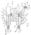
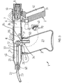
- a vacuum gun assembly 1 comprising a vacuum gun 2 and an attachment 3 for the gun 2.
- the gun assembly 1 will be described by way of example with reference to use in evacuating brake fluid from a vehicle brake system.
Landscapes
- Engineering & Computer Science (AREA)
- Transportation (AREA)
- Mechanical Engineering (AREA)
- Valves And Accessory Devices For Braking Systems (AREA)
- Loading And Unloading Of Fuel Tanks Or Ships (AREA)
- Compressors, Vaccum Pumps And Other Relevant Systems (AREA)
- Vehicle Cleaning, Maintenance, Repair, Refitting, And Outriggers (AREA)
- Braking Systems And Boosters (AREA)
- Jet Pumps And Other Pumps (AREA)
- Reciprocating Pumps (AREA)
- Massaging Devices (AREA)
Claims (20)
- Anbauteil (3) für eine Ansaugpumpe (2) zum Entleeren und Beinhalten einer Flüssigkeit aus einem Flüssigkeitsreservoir, wobei das Anbauteil (3) hat:einen Körper (21) mit einem Einlaß (22) für die Flüssigkeit und einem Auslaß (24), wobei der Auslaß (24) an der Pumpe (2) befestigbar ist;eine Kopplung (26) zwischen dem Einlaß (22) und dem Auslaß (24) ;einen Behälter (27), der lösbar an der Kopplung (26) befestigbar ist;einen ersten Verbindungsgang (33, 34), der sich zwischen dem Einlaß (22) und dem Behälter (27) erstreckt;einen zweiten Verbindungsgang (35, 36), der sich zwischen dem Behälter (27) und dem Auslaß (24) erstreckt; undein Betätigungselement, das mit wenigstens mit einem der Verbindungsgänge verbunden ist und das bewegbar ist, um den verbundenen Verbindungsgang entweder zu schließen oder zu öffnen, und wenn in dem Anbauteil (3) durch die Pumpe (2) ein Unterdruck erzeugt wird und das Betätigungselement in der offenen Stellung ist, kann die Flüssigkeit von dem Behälter (27) aufgenommen werden.
- Anbauteil (3) nach Anspruch 1, das zudem ein Schwimmerventil (83) hat, das in dem zweiten Verbindungsgang (35) angeordnet ist und das diesen Verbindungsgang (35) blockiert, wenn der Behälter (27) voll mit Flüssigkeit ist.
- Anbauteil (3) nach Anspruch 1 oder Anspruch 2, wobei das Betätigungselement aus einem Auslaufventil (70) besteht, das zwischen der offenen und der geschlossenen Stellung bewegbar ist.
- Anbauteil (3) nach Anspruch 3, wobei das Auslaufventil (70) in einem Zentrieransatz (43) aufgenommen ist, der sich von dem Anbauteilkörper (21) erstreckt, und das Auslaufventil (70) ist zum Schließen oder Öffnen beider der Verbindungsgänge geeignet.
- Anbauteil (3) nach Anspruch 4, wobei der erste Verbindungsgang (33, 34) in einem Teil durch ein lösbares mehrteiliges Zuführungsrohr (60, 46, 47) gegeben ist, das sich von dem Einlaß (22) zu dem Zentrieransatz (43) erstreckt.
- Anbauteil (3) nach Anspruch 5, wobei der Einlaß (22) an dem Ende einer Düsenbuchse (25) befindet, und die Düsenbuchse (25) ist von dem Rest des Körpers (21) lösbar.
- Anbauteil (3) nach Anspruch 6, das zudem einen Schlauch (23) hat, der an der Düsenbuchse (25) befestigbar ist.
- Anbauteil (3) nach einem der vorhergehenden Ansprüche, wobei der Behälter (27) Verstärkungsstrukturen hat, um zu verhindern, daß die Wände des Behälters (27) unter Unterdruck einfallen.
- Unterdruckpistolenanordnung (1) zum Entleeren und Beinhalten einer ersten Flüssigkeit von einem Flüssigkeitsreservoir, wobei die Pistolenanordnung (1) eine Unterdruckpistole (2) und ein Anbauteil (3) für die Pistole (2) aufweist, wobei die Pistole (2) hat:einen Körper (4) mit einem Griff (5), einem Pistolenlauf (6) und einer Bohrung (7), die sich durch den Pistolenlauf (6) von einem vorderen Ende zu einem hinteren Ende der Pistole (2) erstreckt;einen Venturi-Motor (10) mit einer Bohrung (7); undeinen Einlaß in den Körper (4) für eine zweite Flüssigkeit, die den Venturi-Motor (10) antreibt, und die zweite Flüssigkeit durch das Hinterende der Pistole (2) abfließt, so daß ein Unterdruck in dem Anbauteil (3) erzeugt wird, wobei das Anbauteil (3) hat:einen Körper (21) mit einem Einlaß (22) für die erste Flüssigkeit und einem Auslaß (24), und der Auslaß (24) ist an dem Vorderende der Pistole (2) befestigbar;eine Kopplung (26) zwischen dem Anbauteilkörpereinlaß (22) und -auslaß (24);einen Behälter (27), der lösbar an der Kopplung (26) befestigbar ist;einen ersten Verbindungsgang (33, 34), der sich zwischen dem Anbauteilkörpereinlaß (22) und dem Behälter (27) erstreckt;einen zweiten Verbindungsgang (35, 36), der sich zwischen dem Behälter (27) und dem Auslaß (24) erstreckt; undein Betätigungselement, das mit wenigstens einem der Verbindungsgänge verbunden ist und das bewegbar ist, um den verbundenen Verbindungsgang entweder zu schließen oder zu öffnen, und wenn durch die Pistole (2) ein Unterdruck in dem Anbauteil (3) erzeugt wird und das Betätigungselement in der offenen Stellung ist, kann die erste Flüssigkeit von dem Behälter (27) aufgenommen werden.
- Anordnung (1) nach Anspruch 9, die zudem ein in dem zweiten Verbindungsgang (35) angeordnetes Schwimmerventil (83) hat, das diesen Verbindungsgang (35) blockiert, wenn der Behälter (27) voll mit der ersten Flüssigkeit ist.
- Anordnung (1) nach Anspruch 9 oder Anspruch 10, wobei das Betätigungselement aus einem Auslaufventil (70) besteht, das zwischen der offenen und geschlossenen Stellung bewegbar ist.
- Anordnung (1) nach Anspruch 11, wobei das Auslaufventil (70) in einem Zentrieransatz (43) aufgenommen ist, der sich von dem Anbauteilkörper (21) erstreckt, und das Auslaufventil (70) ist zum Schließen oder Öffnen beider Verbindungsgänge geeignet.
- Anordnung (1) nach Anspruch 12, wobei der erste Verbindungsgang (33) in einem Teil durch ein lösbares mehrteiliges Zuführungsrohr (60, 46, 47) gegeben ist, das sich von dem Anbauteilkörpereinlaß (22) zu dem Zentrieransatz (43) erstreckt.
- Anordnung (1) nach Anspruch 13, wobei der Anbauteilkörpereinlaß (22) sich an dem Ende einer Düsenbuchse (25) befindet, und die Düsenbuchse (25) lösbar von dem Rest des Anbauteilkörpers (21) ist.
- Anordnung (1) nach Anspruch 14, die zudem einen Schlauch (23) hat, der an der Düsenbuchse (25) befestigbar ist.
- Anordnung (1) nach einem der Ansprüche 9 bis 15, wobei der Behälter (27) Verstärkungsstrukturen hat, um zu verhindern, daß die Wände des Behälters (27) unter Unterdruck einfallen.
- Anordnung (1) nach einem der Ansprüche 9 bis 16, wobei der Auslaß (24) einen ausreichenden Durchmesser zum hermetischen Abdichten um das Vorderende der Pistole (2) hat.
- Anordnung (1) nach einem der Ansprüche 9 bis 17, wobei die Pistole (2) eine perforierte Platte (18) hat, die das Ablaufende des Venturi-Motors (10) abdeckt, um das Geräusch der zweiten die Pistole (2) verlassenden Flüssigkeit zu reduzieren.
- Anordnung (1) nach Anspruch 18, wobei die Pistole (2) einen porösen Einsatz (17) angrenzend an die perforierte Platte (18) hat, um das Geräusch der zweiten Flüssigkeit vor dem Ablaufen zu reduzieren.
- Anordnung (1) nach Anspruch 19, wobei der Einsatz (17) aus Schaum hergestellt ist.
Applications Claiming Priority (3)
| Application Number | Priority Date | Filing Date | Title |
|---|---|---|---|
| AUPQ5651A AUPQ565100A0 (en) | 2000-02-15 | 2000-02-15 | Vacuum gun assembly |
| AUPQ565100 | 2000-02-15 | ||
| PCT/AU2001/000127 WO2001060671A1 (en) | 2000-02-15 | 2001-02-12 | An attachment for a vacuum pump |
Publications (3)
| Publication Number | Publication Date |
|---|---|
| EP1189792A1 EP1189792A1 (de) | 2002-03-27 |
| EP1189792A4 EP1189792A4 (de) | 2004-06-16 |
| EP1189792B1 true EP1189792B1 (de) | 2007-04-18 |
Family
ID=3819767
Family Applications (1)
| Application Number | Title | Priority Date | Filing Date |
|---|---|---|---|
| EP01903519A Expired - Lifetime EP1189792B1 (de) | 2000-02-15 | 2001-02-12 | Zusatzgerät für eine vakuumpumpe |
Country Status (7)
| Country | Link |
|---|---|
| US (1) | US6446683B1 (de) |
| EP (1) | EP1189792B1 (de) |
| JP (1) | JP2003522679A (de) |
| AT (1) | ATE359945T1 (de) |
| AU (1) | AUPQ565100A0 (de) |
| DE (1) | DE60127912T2 (de) |
| WO (1) | WO2001060671A1 (de) |
Families Citing this family (3)
| Publication number | Priority date | Publication date | Assignee | Title |
|---|---|---|---|---|
| AUPR387801A0 (en) | 2001-03-21 | 2001-04-12 | Abw Australia Pty. Ltd. | An attachment for a vacuum pump |
| AUPR850901A0 (en) * | 2001-10-26 | 2001-11-29 | Abw Australia Pty. Ltd. | An apparatus for collecting and containing fluid |
| US7395755B1 (en) | 2006-02-13 | 2008-07-08 | Deese Henry W | Container crusher and method of use thereof |
Family Cites Families (9)
| Publication number | Priority date | Publication date | Assignee | Title |
|---|---|---|---|---|
| US1439295A (en) * | 1921-05-13 | 1922-12-19 | Craig Hugh | Pump |
| AU620511B2 (en) * | 1990-04-30 | 1992-02-20 | Tseng, Tien-Tsai | A portable oil suction device |
| US5265653A (en) * | 1992-11-16 | 1993-11-30 | Herlth August H | Portable pneumatic liquid transfer assembly |
| US5497864A (en) * | 1995-06-20 | 1996-03-12 | Chrysler Corporation | Hydraulic brake bleeder apparatus |
| GB2304840B (en) * | 1995-09-06 | 1998-11-11 | Rover Group | Vacuum bleeding equipment |
| AUPO987597A0 (en) * | 1997-10-17 | 1997-11-13 | Abw Australia Pty. Ltd. | A gun for flushing vehicle cooling systems |
| US5964326A (en) | 1998-03-17 | 1999-10-12 | Lee; Kin Bong | Apparatus for bleeding and refilling hydraulic brake system |
| FR2777249B1 (fr) * | 1998-04-10 | 2000-07-13 | Gilles Bompuis | Purgeur par aspiration ou pression de circuit hydraulique de freinage ou d'embrayage |
| GB0220320D0 (en) | 2002-09-02 | 2002-10-09 | Zebedee Alan R | Hinge |
-
2000
- 2000-02-15 AU AUPQ5651A patent/AUPQ565100A0/en not_active Abandoned
-
2001
- 2001-02-12 US US09/926,306 patent/US6446683B1/en not_active Expired - Lifetime
- 2001-02-12 DE DE60127912T patent/DE60127912T2/de not_active Expired - Lifetime
- 2001-02-12 JP JP2001559740A patent/JP2003522679A/ja active Pending
- 2001-02-12 EP EP01903519A patent/EP1189792B1/de not_active Expired - Lifetime
- 2001-02-12 AT AT01903519T patent/ATE359945T1/de not_active IP Right Cessation
- 2001-02-12 WO PCT/AU2001/000127 patent/WO2001060671A1/en not_active Ceased
Also Published As
| Publication number | Publication date |
|---|---|
| DE60127912D1 (de) | 2007-05-31 |
| JP2003522679A (ja) | 2003-07-29 |
| US20020139435A1 (en) | 2002-10-03 |
| EP1189792A1 (de) | 2002-03-27 |
| US6446683B1 (en) | 2002-09-10 |
| ATE359945T1 (de) | 2007-05-15 |
| AUPQ565100A0 (en) | 2000-03-09 |
| WO2001060671A1 (en) | 2001-08-23 |
| EP1189792A4 (de) | 2004-06-16 |
| DE60127912T2 (de) | 2008-01-17 |
Similar Documents
| Publication | Publication Date | Title |
|---|---|---|
| CN101466478B (zh) | 纹理喷涂器 | |
| CA2351596A1 (en) | A gear pump and replaceable reservoir for a fluid sprayer | |
| EP1184084A3 (de) | Schlauchendsprühgerät vom Ansaugtyp | |
| US11896986B2 (en) | Nozzle device applied to high-pressure cleaning machine and handheld high-pressure cleaning machine | |
| CN103052515B (zh) | 无内胎轮胎就座装置 | |
| DE59008330D1 (de) | Austragvorrichtung für Medien. | |
| US6446683B1 (en) | Attachment for a vacuum pump | |
| US7354255B1 (en) | Piston vibratory pump | |
| US4060108A (en) | Vapor control spout | |
| AU770421B2 (en) | An attachment for a vacuum pump | |
| US3933179A (en) | Water and concentrate supply valves for proportioning mixer-dispenser | |
| US20040016047A1 (en) | Flushing device for toilets | |
| JP2017087116A (ja) | 二流体ノズル | |
| CA2404427A1 (en) | Valve assembly for a pressure flush system | |
| US20040159368A1 (en) | Quick fill cap for a toy water gun | |
| US6279176B1 (en) | Low water toilet | |
| CN1938218B (zh) | 双成分材料混合和分配装置 | |
| US6305393B1 (en) | Flushing system with pressurized air | |
| US4014363A (en) | Water and concentrate supply valves for proportioning mixer-dispenser | |
| US12521738B2 (en) | Foam-at-a-distance dispensers having small volume pump chambers and valve arrangements for same | |
| US6681812B2 (en) | Attachment for a vacuum pump | |
| CN217150506U (zh) | 一种压力式冲水装置和便器 | |
| WO2002061312A3 (en) | Water flow control valve | |
| EP1106462A3 (de) | Steuervorrichtung für Bremsflüssigkeitsdruck | |
| CN214262383U (zh) | 一种花洒 |
Legal Events
| Date | Code | Title | Description |
|---|---|---|---|
| PUAI | Public reference made under article 153(3) epc to a published international application that has entered the european phase |
Free format text: ORIGINAL CODE: 0009012 |
|
| 17P | Request for examination filed |
Effective date: 20011114 |
|
| AK | Designated contracting states |
Kind code of ref document: A1 Designated state(s): AT BE CH CY DE DK ES FI FR GB GR IE IT LI LU MC NL PT SE TR |
|
| AX | Request for extension of the european patent |
Free format text: AL;LT;LV;MK;RO;SI |
|
| A4 | Supplementary search report drawn up and despatched |
Effective date: 20040429 |
|
| GRAP | Despatch of communication of intention to grant a patent |
Free format text: ORIGINAL CODE: EPIDOSNIGR1 |
|
| GRAS | Grant fee paid |
Free format text: ORIGINAL CODE: EPIDOSNIGR3 |
|
| GRAA | (expected) grant |
Free format text: ORIGINAL CODE: 0009210 |
|
| AK | Designated contracting states |
Kind code of ref document: B1 Designated state(s): AT BE CH CY DE DK ES FI FR GB GR IE IT LI LU MC NL PT SE TR |
|
| PG25 | Lapsed in a contracting state [announced via postgrant information from national office to epo] |
Ref country code: CH Free format text: LAPSE BECAUSE OF FAILURE TO SUBMIT A TRANSLATION OF THE DESCRIPTION OR TO PAY THE FEE WITHIN THE PRESCRIBED TIME-LIMIT Effective date: 20070418 Ref country code: FI Free format text: LAPSE BECAUSE OF FAILURE TO SUBMIT A TRANSLATION OF THE DESCRIPTION OR TO PAY THE FEE WITHIN THE PRESCRIBED TIME-LIMIT Effective date: 20070418 Ref country code: LI Free format text: LAPSE BECAUSE OF FAILURE TO SUBMIT A TRANSLATION OF THE DESCRIPTION OR TO PAY THE FEE WITHIN THE PRESCRIBED TIME-LIMIT Effective date: 20070418 |
|
| REG | Reference to a national code |
Ref country code: CH Ref legal event code: EP |
|
| REG | Reference to a national code |
Ref country code: IE Ref legal event code: FG4D |
|
| REF | Corresponds to: |
Ref document number: 60127912 Country of ref document: DE Date of ref document: 20070531 Kind code of ref document: P |
|
| PG25 | Lapsed in a contracting state [announced via postgrant information from national office to epo] |
Ref country code: SE Free format text: LAPSE BECAUSE OF FAILURE TO SUBMIT A TRANSLATION OF THE DESCRIPTION OR TO PAY THE FEE WITHIN THE PRESCRIBED TIME-LIMIT Effective date: 20070718 |
|
| PG25 | Lapsed in a contracting state [announced via postgrant information from national office to epo] |
Ref country code: ES Free format text: LAPSE BECAUSE OF FAILURE TO SUBMIT A TRANSLATION OF THE DESCRIPTION OR TO PAY THE FEE WITHIN THE PRESCRIBED TIME-LIMIT Effective date: 20070729 |
|
| PG25 | Lapsed in a contracting state [announced via postgrant information from national office to epo] |
Ref country code: PT Free format text: LAPSE BECAUSE OF FAILURE TO SUBMIT A TRANSLATION OF THE DESCRIPTION OR TO PAY THE FEE WITHIN THE PRESCRIBED TIME-LIMIT Effective date: 20070918 |
|
| REG | Reference to a national code |
Ref country code: CH Ref legal event code: PL |
|
| NLV1 | Nl: lapsed or annulled due to failure to fulfill the requirements of art. 29p and 29m of the patents act | ||
| PG25 | Lapsed in a contracting state [announced via postgrant information from national office to epo] |
Ref country code: AT Free format text: LAPSE BECAUSE OF FAILURE TO SUBMIT A TRANSLATION OF THE DESCRIPTION OR TO PAY THE FEE WITHIN THE PRESCRIBED TIME-LIMIT Effective date: 20070418 |
|
| EN | Fr: translation not filed | ||
| PG25 | Lapsed in a contracting state [announced via postgrant information from national office to epo] |
Ref country code: BE Free format text: LAPSE BECAUSE OF FAILURE TO SUBMIT A TRANSLATION OF THE DESCRIPTION OR TO PAY THE FEE WITHIN THE PRESCRIBED TIME-LIMIT Effective date: 20070418 |
|
| PG25 | Lapsed in a contracting state [announced via postgrant information from national office to epo] |
Ref country code: NL Free format text: LAPSE BECAUSE OF FAILURE TO SUBMIT A TRANSLATION OF THE DESCRIPTION OR TO PAY THE FEE WITHIN THE PRESCRIBED TIME-LIMIT Effective date: 20070418 Ref country code: DK Free format text: LAPSE BECAUSE OF FAILURE TO SUBMIT A TRANSLATION OF THE DESCRIPTION OR TO PAY THE FEE WITHIN THE PRESCRIBED TIME-LIMIT Effective date: 20070418 |
|
| PLBE | No opposition filed within time limit |
Free format text: ORIGINAL CODE: 0009261 |
|
| STAA | Information on the status of an ep patent application or granted ep patent |
Free format text: STATUS: NO OPPOSITION FILED WITHIN TIME LIMIT |
|
| 26N | No opposition filed |
Effective date: 20080121 |
|
| PG25 | Lapsed in a contracting state [announced via postgrant information from national office to epo] |
Ref country code: FR Free format text: LAPSE BECAUSE OF FAILURE TO SUBMIT A TRANSLATION OF THE DESCRIPTION OR TO PAY THE FEE WITHIN THE PRESCRIBED TIME-LIMIT Effective date: 20071214 Ref country code: GR Free format text: LAPSE BECAUSE OF FAILURE TO SUBMIT A TRANSLATION OF THE DESCRIPTION OR TO PAY THE FEE WITHIN THE PRESCRIBED TIME-LIMIT Effective date: 20070719 Ref country code: IT Free format text: LAPSE BECAUSE OF FAILURE TO SUBMIT A TRANSLATION OF THE DESCRIPTION OR TO PAY THE FEE WITHIN THE PRESCRIBED TIME-LIMIT Effective date: 20070418 |
|
| PG25 | Lapsed in a contracting state [announced via postgrant information from national office to epo] |
Ref country code: MC Free format text: LAPSE BECAUSE OF NON-PAYMENT OF DUE FEES Effective date: 20080228 |
|
| PG25 | Lapsed in a contracting state [announced via postgrant information from national office to epo] |
Ref country code: FR Free format text: LAPSE BECAUSE OF FAILURE TO SUBMIT A TRANSLATION OF THE DESCRIPTION OR TO PAY THE FEE WITHIN THE PRESCRIBED TIME-LIMIT Effective date: 20070418 |
|
| PG25 | Lapsed in a contracting state [announced via postgrant information from national office to epo] |
Ref country code: IE Free format text: LAPSE BECAUSE OF NON-PAYMENT OF DUE FEES Effective date: 20080212 |
|
| PG25 | Lapsed in a contracting state [announced via postgrant information from national office to epo] |
Ref country code: CY Free format text: LAPSE BECAUSE OF FAILURE TO SUBMIT A TRANSLATION OF THE DESCRIPTION OR TO PAY THE FEE WITHIN THE PRESCRIBED TIME-LIMIT Effective date: 20070418 |
|
| PG25 | Lapsed in a contracting state [announced via postgrant information from national office to epo] |
Ref country code: LU Free format text: LAPSE BECAUSE OF NON-PAYMENT OF DUE FEES Effective date: 20080212 |
|
| PG25 | Lapsed in a contracting state [announced via postgrant information from national office to epo] |
Ref country code: TR Free format text: LAPSE BECAUSE OF FAILURE TO SUBMIT A TRANSLATION OF THE DESCRIPTION OR TO PAY THE FEE WITHIN THE PRESCRIBED TIME-LIMIT Effective date: 20070418 |
|
| PGFP | Annual fee paid to national office [announced via postgrant information from national office to epo] |
Ref country code: DE Payment date: 20160224 Year of fee payment: 16 |
|
| PGFP | Annual fee paid to national office [announced via postgrant information from national office to epo] |
Ref country code: GB Payment date: 20160222 Year of fee payment: 16 |
|
| REG | Reference to a national code |
Ref country code: DE Ref legal event code: R119 Ref document number: 60127912 Country of ref document: DE |
|
| GBPC | Gb: european patent ceased through non-payment of renewal fee |
Effective date: 20170212 |
|
| PG25 | Lapsed in a contracting state [announced via postgrant information from national office to epo] |
Ref country code: DE Free format text: LAPSE BECAUSE OF NON-PAYMENT OF DUE FEES Effective date: 20170901 |
|
| PG25 | Lapsed in a contracting state [announced via postgrant information from national office to epo] |
Ref country code: GB Free format text: LAPSE BECAUSE OF NON-PAYMENT OF DUE FEES Effective date: 20170212 |