EP1190779A2 - Dispositif et procédé de détection de timbres postaux, et dispositif et procédé de traitement de lettres - Google Patents
Dispositif et procédé de détection de timbres postaux, et dispositif et procédé de traitement de lettres Download PDFInfo
- Publication number
- EP1190779A2 EP1190779A2 EP01122039A EP01122039A EP1190779A2 EP 1190779 A2 EP1190779 A2 EP 1190779A2 EP 01122039 A EP01122039 A EP 01122039A EP 01122039 A EP01122039 A EP 01122039A EP 1190779 A2 EP1190779 A2 EP 1190779A2
- Authority
- EP
- European Patent Office
- Prior art keywords
- stamp
- section
- area
- letter
- face value
- Prior art date
- Legal status (The legal status is an assumption and is not a legal conclusion. Google has not performed a legal analysis and makes no representation as to the accuracy of the status listed.)
- Withdrawn
Links
Images







Classifications
-
- B—PERFORMING OPERATIONS; TRANSPORTING
- B07—SEPARATING SOLIDS FROM SOLIDS; SORTING
- B07C—POSTAL SORTING; SORTING INDIVIDUAL ARTICLES, OR BULK MATERIAL FIT TO BE SORTED PIECE-MEAL, e.g. BY PICKING
- B07C3/00—Sorting according to destination
- B07C3/10—Apparatus characterised by the means used for detection ofthe destination
- B07C3/14—Apparatus characterised by the means used for detection ofthe destination using light-responsive detecting means
-
- G—PHYSICS
- G06—COMPUTING OR CALCULATING; COUNTING
- G06V—IMAGE OR VIDEO RECOGNITION OR UNDERSTANDING
- G06V10/00—Arrangements for image or video recognition or understanding
- G06V10/20—Image preprocessing
- G06V10/24—Aligning, centring, orientation detection or correction of the image
- G06V10/242—Aligning, centring, orientation detection or correction of the image by image rotation, e.g. by 90 degrees
-
- G—PHYSICS
- G06—COMPUTING OR CALCULATING; COUNTING
- G06V—IMAGE OR VIDEO RECOGNITION OR UNDERSTANDING
- G06V10/00—Arrangements for image or video recognition or understanding
- G06V10/20—Image preprocessing
- G06V10/25—Determination of region of interest [ROI] or a volume of interest [VOI]
-
- G—PHYSICS
- G06—COMPUTING OR CALCULATING; COUNTING
- G06V—IMAGE OR VIDEO RECOGNITION OR UNDERSTANDING
- G06V10/00—Arrangements for image or video recognition or understanding
- G06V10/40—Extraction of image or video features
- G06V10/50—Extraction of image or video features by performing operations within image blocks; by using histograms, e.g. histogram of oriented gradients [HoG]; by summing image-intensity values; Projection analysis
- G06V10/507—Summing image-intensity values; Histogram projection analysis
-
- G—PHYSICS
- G06—COMPUTING OR CALCULATING; COUNTING
- G06V—IMAGE OR VIDEO RECOGNITION OR UNDERSTANDING
- G06V20/00—Scenes; Scene-specific elements
- G06V20/60—Type of objects
- G06V20/66—Trinkets, e.g. shirt buttons or jewellery items
Definitions
- This invention relates to a stamp detecting device, stamp detecting method, letter processing apparatus and letter processing method for detecting a stamp affixed to a postal letter, for example.
- this invention relates to a letter processing apparatus and letter processing method for sorting a postal letter by use of the above stamp detecting device.
- a stamp detecting device as various threshold values (for example, a threshold value used for distinguishing the stamp area and the ground area of the letter) used for detecting a stamp affixed to a postal letter, predetermined values or values derived by a statistical calculation based on an image of the letter are used when the stamp is detected based on a density projection value.
- threshold values for example, a threshold value used for distinguishing the stamp area and the ground area of the letter
- predetermined values or values derived by a statistical calculation based on an image of the letter are used when the stamp is detected based on a density projection value.
- the identification method which is not influenced by the affixed orientation of the stamp is used. Also, when the type of stamp affixed to the postal letter is identified, the identification method is effected without using knowledge of the face value of the stamp.
- the identification method which does not depend on the affixed orientation of the stamp has a problem that the identification performance is lower than that of the identification method which depends on the affixed orientation of the stamp.
- the identification method which depends on the affixed orientation of the stamp since it does not utilize the knowledge of the face value of the stamp, there occurs a problem that a lot of identification errors are made.
- an object of this invention is to provide a stamp detecting device, stamp detecting method, letter processing apparatus and letter processing method which makes it easy to set threshold values used for detecting a stamp and can always stably effect the stamp detecting operation.
- Another object of this invention is to provide a stamp detecting device, stamp detecting method, letter processing apparatus and letter processing method capable of more precisely detecting a stamp.
- a stamp detecting device comprises an image input section which inputs an image of a letter having at least one stamp affixed thereto; and a stamp detecting section which detects a stamp by determining a gap area as an internal area of the stamp if the size of the gap area is within a preset permissible range in a case where the gap area which is partly determined as an external area of the stamp is present in an area which is determined as the internal area of the stamp affixed to the letter based on the image input from the image input section.
- a letter processing apparatus comprises an image input section which inputs an image of a letter having at least one stamp affixed thereto; a stamp detecting section which detects a stamp by determining a gap area as an internal area of the stamp if the size of the gap area is within a preset permissible range in a case where the gap area which is partly determined as an external area of the stamp is present in an area which is determined as the internal area of the stamp affixed to the letter based on the image input from the image input section; a stamp identifying section which identifies a type of the stamp detected by the stamp detecting section; a stamp face value calculating section which derives a total face value of the stamps affixed to the letter based on the type of the stamp identified by the stamp identifying section; and a sorting section which sorts the letter based on the total face value of the stamps derived by the stamp face value calculating section.
- a letter processing apparatus comprises an image input section which inputs an image of a letter having at least one stamp affixed thereto; a stamp detecting section which detects a stamp affixed to the letter based on a density or luminance projection value derived according to the image input by the image input section; a stamp identifying section which identifies a type of the stamp detected by the stamp detecting section; a stamp face value calculating section which derives a total face value of the stamps affixed to the letter based on the type of the stamp identified by the stamp identifying section; and a sorting section which sorts the letter based on the total face value of the stamps derived by the stamp face value calculating section.
- a stamp detecting method comprises inputting an image of a letter having at least one stamp affixed thereto; and detecting a stamp by determining a gap area as an internal area of the stamp if the size of the gap area is within a preset permissible range in a case where the gap area which is partly determined as an external area of the stamp is present in an area which is determined as the internal area of the stamp affixed to the letter based on the image input in the image input step.
- a letter processing method comprises inputting an image of a letter having at least one stamp affixed thereto; detecting a stamp by determining a gap area as an internal area of the stamp if the size of the gap area is within a preset permissible range in a case where the gap area which is partly determined as an external area of the stamp is present in an area which is determined as the internal area of the stamp affixed to the letter based on the image input in the image input step; identifying a type of the stamp detected in the stamp detecting step; deriving a total face value of the stamps affixed to the letter based on the type of the stamp identified in the identifying step; and sorting the letter based on the total face value of the stamps derived in the total face value deriving step.
- a letter processing method comprises inputting an image of a letter having at least one stamp affixed thereto; deriving a density projection value based on the input image; detecting a stamp affixed to the letter based on the thus derived projection value; identifying a type of the detected stamp; deriving a total face value of the stamps affixed to the letter based on the type of the stamp thus identified; and sorting the letter based on the thus derived total face value of the stamps.
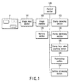
- FIG. 1 schematically shows the configuration of a letter processing apparatus to which a stamp detecting device according to the first embodiment of this invention is applied.
- the letter processing apparatus includes an image input section 101 which inputs an image (which is hereinafter referred to as a letter image) of a postal letter P having a stamp or stamps affixed thereto, an image memory 102 which temporarily stores an image input by the image input section 101, a stamp detecting section 103 which detects a stamp area from the letter image stored in the image memory 102, a stamp identifying section 104 which identifies the type of stamp based on the image of the stamp area detected by the stamp detecting section 103, a stamp face value determining section 105 which derives a total face value of the stamps based on the type of stamp identified by the stamp identifying section 104, a postmarking section (imprinting section) 106 which imprints a postmark on the letter P based on the coordinate value of the stamp area detected by the stamp detecting section 103, a sorting
- the image input section 101 inputs an image of the letter P by optically scanning the letter P and photo-electrically converting the image of the letter P and stores the image into the image memory 102 (S1).
- the stamp detecting section 103 derives a density projection value from the letter image stored in the image memory 102 (S2) and detects a stamp area based on the thus derived projection value (S3).
- the coordinate value of the stamp area detected at this time is used for determining the imprinting position in the postmarking process (S4) by the postmarking section 106.
- the stamp identifying section 106 identifies the type of the stamp affixed to the letter P based on the image of the stamp area detected by the stamp detecting section 103 (S5). Then, the stamp face value determining section 105 determines the total face value of the stamps based on the types of the stamps identified by the stamp identifying section 104 (S6). The total face value of the stamps derived at this time is used for the sorting process (S7) for the respective types (ordinary mail, express mail and the like) of the letters P by the sorting processing section 107.
- the stamp detecting section 103 detects the stamp by the following process, for example.
- a case wherein a projection value is derived based on luminance is explained, but the same process can also be effected if a projection value is derived based on density. That is, since the luminance and density are set in an opposed relation, the density becomes lower when the luminance becomes higher and the density becomes higher when the luminance becomes lower, for example. Therefore, if the following process is effected by use of the projection value based on the density, the determination results for the threshold values will be reversed.
- FIG. 3 An outline of the stamp detecting process is shown in FIG. 3 (which will be described in detail later).
- a luminance projection value is derived in the lateral orientation with respect to an area in which a stamp is considered to be affixed ((1) of FIG. 3). Since the luminance of the ground area of the letter P is generally high and the luminance of the stamp area is low, it is determined that the Y coordinate of the stamp area ranges from Ys to Ye by the threshold determining process which will be described later. If a plurality of stamps are affixed in the vertical orientation, plural sets of Ys and Ye are detected, and in such a case, the following process is effected for each set of Ys and Ye.
- a luminance projection value is derived in the vertical orientation for a band area limited by derived Ys, Ye ((2) of FIG. 3). Also, in this case, it is determined that the X coordinate of the stamp area ranges from Xs to Xe by the threshold determination process which is similar to that in the lateral orientation. Thus, the stamp area is detected. In the postmarking section 106, the postmarking operation is effected based on the coordinate information of the stamp area thus detected.
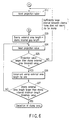
- the stamp detecting section 103 determines whether or not the derived projection value is smaller than a stamp internal area threshold value A1 (S11), and if it is larger than the threshold value, the stamp detecting section determines that it is not the stamp internal portion and performs the step of checking the projection value of a next area (S12). If it is determined in the step S11 that the projection value is smaller than the threshold value A1, the stamp detecting section 103 determines that the area is the stamp internal area and sets the length of the stamp internal area to "1" (S13).
- the stamp detecting section 103 checks whether or not the projection value of a next area is smaller than the stamp internal area threshold value A1 (S14, S15), and if the projection value is smaller than the threshold value A1, the stamp detecting section determines that it is a stamp internal portion and increments the length of the stamp internal area by one (S16).
- the stamp detecting section 103 determines that the area does not seem to be the stamp internal area (it seems to be a stamp external portion), sets the stamp internal gap length to "1" (S17) and then performs the step of checking the projection value of a next area (S18). After this, the stamp detecting section 103 checks whether or not the projection value of a next area is smaller than the stamp internal area threshold value A1 (S19), and if the projection value is not smaller than the threshold value A1, the stamp detecting section determines that it is a stamp external portion and increments the stamp internal gap length by one (S20).
- the stamp detecting section 103 checks whether or not the stamp internal gap length is smaller than a stamp internal gap permissible length threshold value A2 (S21), and if the gap length is smaller than the threshold value A2, the stamp detecting section returns the process to the step S18. At this time, if it is determined in the next step S19 that the projection value of the next area is smaller than the stamp internal area threshold value A1, the stamp detecting section 103 returns the process to the step S16 again and determines that the stamp internal area is continuous.
- a stamp internal gap permissible length threshold value A2 S21
- the stamp detecting section 103 determines that an area which may be determined as a stamp external portion is partially contained in the internal portion of the stamp and permits the existence of the area.
- the stamp detecting section 103 determines that the gap length is sufficiently large and the area is a stamp external area and performs the step S22.
- the stamp detecting section 103 checks whether the stamp internal area length incremented so far is larger than a stamp minimum length threshold value A3. If the area length is not larger than the threshold value A3, the stamp detecting section 103 determines that the area is not a sufficiently large stamp internal area (it is not a stamp) and returns the process to the step S12.
- the stamp detecting section 103 determines that an area which seems to be a stamp is detected and substitutes the stamp internal gap length into the stamp external area length (S23). Then, the stamp detecting section 103 performs the step of checking the projection value of a next area (S24) and checks whether the projection value is larger than a stamp external area threshold value A4 (S25). If the area is not larger than the threshold value A4, the stamp detecting section 103 determines that there is no sufficiently large stamp interval and the area does not seem to be a stamp and returns the process to the step S12 to continuously effect the searching operation.
- the stamp detecting section 103 determines that the area is a stamp external area and increments the stamp external area length by one (S26). Then, the stamp detecting section 103 checks whether the stamp external area length is larger than a stamp interval minimum length threshold value A5 (S27), and if it is not larger than the threshold value A5, the stamp detecting section 103 returns the process to the step S24 to continuously effect the searching operation until a sufficiently large stamp interval is detected. If it is determined in the step S27 that the area length is larger than the threshold value A5, the stamp detecting section 103 determines that a sufficiently large stamp interval is detected and an area which really seems to be a stamp is detected and terminates the stamp detecting process.
- the control section 108 makes rough setting of threshold values to detect a stamp (S31). More specifically, for example, the stamp internal area threshold value A1 is set to a rather large value, the stamp external area threshold value A4 is set to a rather small value, the stamp internal gap permissible length threshold value A2 is set to a rather large value, the stamp minimum length threshold value A3 is set to a rather small value, and the stamp interval minimum length threshold value A5 is set to a rather small value. Then, the stamp detecting section 103 performs the stamp detecting process under the conditions set by the control section 108 (S32).
- a large area including a plurality of stamps is temporarily detected by the rough setting of the threshold values in a case where the boundary between stamps is not clear due to stains of a letter or the printing pattern of the letter or where areas may be detected as a plurality of stamps since white portions exist in a pattern of the stamp internal portion.
- the control section 108 checks the length of a detected area (S33), and if it is proper length, it determines that one stamp area can be correctly detected and terminates the detecting process by the stamp detecting section 103. If it is determined in the step S33 that the length of the detected area is too long, the control section 108 slightly severely sets the threshold values (S34) so that the area can be easily divided and then starts to cause the stamp detecting section 103 to perform the stamp detecting process with respect to the internal portion of the area.
- S33 the threshold values
- the stamp internal area threshold value A1 is set on the small side
- the stamp external area threshold value A4 is set on the large side
- the stamp internal gap permissible length threshold value A2 is set on the small side
- the stamp minimum length threshold value A3 is set on the large side
- the stamp interval minimum length threshold value A5 is set on the large side, for example.
- the stamp identifying section 104 a process for identifying the type of stamp is effected with respect to a stamp area detected by the stamp detecting section 103.
- the identifying process may be effected by previously preparing standard patterns "Template” of stamps for respective types, calculating the similarity by deriving the inner product of the standard pattern and a detected stamp area (input pattern) "Detect” and determining the type based on the magnitude of the calculated similarity.
- the similarity is calculated according to the following equation.
- Various identifying methods such as a known multiple similarity method, local correlation method, partial spacing method, main component analyzing method, canonical determining/analyzing method can be used other than the above simple pattern matching method.
- an identification process which can cope with large variations in the pattern, such as a change or deviation in the light and shade, can be performed.
- the stamp face value determining section 105 determines the total face values of stamps affixed to the letter P based on type information of the stamp identified by the stamp identifying section 104 and an information table 109a which stores a table indicating a correspondence relation between the type of stamp and the face value as shown in FIG. 9.
- the sorting processing section 107 sorts and processes the letter P according to the type, such as ordinary mail, express mail or the like, based on the total face value of the stamps determined by the stamp face value determining section 105.
- the stamp identifying section 104 has standard patterns (templates) corresponding to a variety of affixed stamp orientations (rotating directions) of 0°, 90°, 180°, 270° (and angles therebetween), for example, which are previously stored in the memory section 109 and derives matching degrees between the respective standard patterns and the input pattern (the pattern of the detected stamp).
- the type and affixed orientation of the stamp are identified by selecting the standard pattern which gives the maximum similarity or similarity larger than a threshold value based on the similarities derived by the matching process.
- the orientation of the whole letter can be determined to be the same as the affixed orientation of the detected stamp.
- the orientation can be determined by the average orientation of the affixed stamps.
- the thus detected orientation information of the letter can be used for the recognition process of the destination address of the letter or the like.
- the whole configuration of a letter processing apparatus according to the third embodiment is similar to that of the first embodiment (FIG. 1) except that a stamp identifying section 104 is provided, as explained below. Portions similar to the first embodiment are not explained.
- a noticed area table 109b which stores information for specifying noticed partial areas is provided in the memory section 109. More specifically, for example, as shown in FIG. 11, the noticed area table 109b which previously stores information for specifying noticed partial areas when the identification process is precisely performed is provided and the precise identification process is performed based on an area specified by the information.
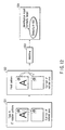
- FIGS. 12 and 13 The outline of the process is shown in FIGS. 12 and 13.
- the second embodiment in which the affixed orientation of the stamp is identified
- the present embodiment in which the identification process is performed with high precision based on the partial area of the stamp, is explained.
- a partial pattern of a noticed area is cut out for each identification candidate based on the noticed area table 109b of FIG. 11 and information on the affixed orientation of the stamp identified (S51).
- the coordinate area obtained at the time of 0° rotation is stored in the noticed area table 109b and the noticed area coordinate of the table is converted based on the affixed orientation of the detected stamp and then the partial pattern is cut out.
- a corresponding partial pattern of an input pattern is cut out (S52). Similarities can be acquired (S54) by performing an identifying process such as a matching process based on the above partial patterns (S53). A more precise identification result can be selected from the plurality of candidates by comparing the similarities.
- stamps of different face values having similar patterns can be precisely identified based on the difference therebetween since the similarity can be checked merely by paying attention to the price expressing figure portion.
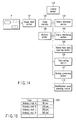
- FIG. 14 The whole configuration of a letter processing apparatus according to the fourth embodiment is shown in FIG. 14.
- the fourth embodiment is similar to the first embodiment (FIG. 1) except that an identification result selecting section 110 is additionally provided, as explained below. Portions similar to the first embodiment are not explained.
- the postage rate is determined by the type; ordinary mail, express mail or the like, and the weight of the letter.
- the price patterns which can be set are limited to certain patterns. Therefore, as shown in FIG. 15, a total face value table 109c which stores the types of total face values which can be set is provided in the memory section 109 and an identification result which is not inconsistent with the total face value is selected.
- the stamp identifying section 104 identifies a stamp area detected by the stamp detecting section 103 (S61). Thus, candidates of an identification result for each stamp area can be obtained (S62). Then, the total amount is calculated for a combination of a plurality of identification candidates (S63). After this, an identification result which is not inconsistent with the total face value is selected by collating the calculated total amount and the total face value patterns in the total face value table 109c of FIG. 15 (S64). Thus, a more precise identification result can be attained.
- FIG. 17 The flow of the process is shown in FIG. 17. Portions which are the same as those of FIG. 2 are denoted by the same reference numerals and the explanation thereof is omitted. That is, the processes such as the image input process, stamp detecting process, stamp identification process and the stamp face value determining process are effected in the same manner as in the first embodiment (the steps S1, S2, S4, S5, S6 in FIG. 2).
- stamp face value determining process is correctly effected (S71), and only if the stamp face value determining process is correctly effected, a postmarking process (S72) and sorting process (S73) are effected. If the stamp face value determining process is not correctly effected, a process for separately sorting the letter is effected as the result of process failure, for example, and then a reject process (S74) is effected.
Landscapes
- Engineering & Computer Science (AREA)
- Physics & Mathematics (AREA)
- General Physics & Mathematics (AREA)
- Multimedia (AREA)
- Theoretical Computer Science (AREA)
- Image Analysis (AREA)
- Character Input (AREA)
- Devices For Checking Fares Or Tickets At Control Points (AREA)
- Image Processing (AREA)
Applications Claiming Priority (2)
| Application Number | Priority Date | Filing Date | Title |
|---|---|---|---|
| JP2000286026 | 2000-09-20 | ||
| JP2000286026A JP2002092674A (ja) | 2000-09-20 | 2000-09-20 | 切手検出装置、切手検出方法、書状処理装置および書状処理方法 |
Publications (2)
| Publication Number | Publication Date |
|---|---|
| EP1190779A2 true EP1190779A2 (fr) | 2002-03-27 |
| EP1190779A3 EP1190779A3 (fr) | 2004-05-06 |
Family
ID=18770002
Family Applications (1)
| Application Number | Title | Priority Date | Filing Date |
|---|---|---|---|
| EP01122039A Withdrawn EP1190779A3 (fr) | 2000-09-20 | 2001-09-13 | Dispositif et procédé de détection de timbres postaux, et dispositif et procédé de traitement de lettres |
Country Status (6)
| Country | Link |
|---|---|
| US (1) | US6934404B2 (fr) |
| EP (1) | EP1190779A3 (fr) |
| JP (1) | JP2002092674A (fr) |
| KR (1) | KR100435125B1 (fr) |
| AU (1) | AU768373B2 (fr) |
| CA (1) | CA2357250C (fr) |
Cited By (2)
| Publication number | Priority date | Publication date | Assignee | Title |
|---|---|---|---|---|
| WO2003035284A3 (fr) * | 2001-10-16 | 2003-08-21 | Deutsche Post Ag | Procede et dispositif pour traiter des informations graphiques situees sur des surfaces d'envois postaux |
| FR2841673A1 (fr) * | 2002-06-26 | 2004-01-02 | Solystic | Chronomarquage d'objets postaux par signature d'image et machine de tri associee |
Families Citing this family (5)
| Publication number | Priority date | Publication date | Assignee | Title |
|---|---|---|---|---|
| JP4281321B2 (ja) * | 2002-10-15 | 2009-06-17 | 日本電気株式会社 | 定形外郵便物の選別・取揃え・押印処理装置 |
| JP2006113820A (ja) * | 2004-10-14 | 2006-04-27 | Sharp Corp | 携帯端末を利用した個人認証システム |
| US20080008376A1 (en) * | 2006-07-07 | 2008-01-10 | Lockheed Martin Corporation | Detection and identification of postal indicia |
| US20080008377A1 (en) * | 2006-07-07 | 2008-01-10 | Lockheed Martin Corporation | Postal indicia categorization system |
| CN102456745B (zh) * | 2010-10-22 | 2013-09-04 | 北京大学 | 一种快闪存储器及其制备方法和操作方法 |
Family Cites Families (20)
| Publication number | Priority date | Publication date | Assignee | Title |
|---|---|---|---|---|
| JPS5936051A (ja) * | 1982-08-23 | 1984-02-28 | Toshiba Corp | 紙葉類の穴検知装置 |
| JPS58140878A (ja) * | 1982-02-17 | 1983-08-20 | Toshiba Corp | 切手検出装置 |
| JPS59164183A (ja) * | 1983-03-09 | 1984-09-17 | Nec Corp | 郵便物等の自動取りそろえ押印装置 |
| JPS62138983A (ja) * | 1985-12-12 | 1987-06-22 | Toshiba Corp | 切手検出装置 |
| JP3038344B2 (ja) * | 1987-02-24 | 2000-05-08 | 株式会社東芝 | 郵便物読取処理装置 |
| JP2713911B2 (ja) * | 1987-07-08 | 1998-02-16 | 株式会社東芝 | 郵便物処理装置 |
| JPH026885A (ja) * | 1988-06-27 | 1990-01-11 | Toshiba Corp | 郵便物の判定装置 |
| JPH03220679A (ja) * | 1990-01-26 | 1991-09-27 | Toshiba Corp | 切手検出装置 |
| JP3394795B2 (ja) * | 1993-07-16 | 2003-04-07 | 株式会社東芝 | 対象物の処理装置及び対象物の処理方法 |
| US5943432A (en) * | 1993-11-17 | 1999-08-24 | Gilmore; Jack R. | Postage due detection system |
| US5537491A (en) * | 1993-11-24 | 1996-07-16 | Xerox Corporation | Analyzing an image or other data to obtain a stable number of groups |
| US5917925A (en) * | 1994-04-14 | 1999-06-29 | Moore; Lewis J. | System for dispensing, verifying and tracking postage and other information on mailpieces |
| US6047085A (en) * | 1994-07-21 | 2000-04-04 | Kabushiki Kaisha Toshiba | Image identifying apparatus |
| JP2715924B2 (ja) * | 1994-08-04 | 1998-02-18 | 日本電気株式会社 | 紙葉類押印装置 |
| JP2730665B2 (ja) * | 1994-12-15 | 1998-03-25 | 北陸先端科学技術大学院大学長 | 文字認識装置および方法 |
| DE19617557A1 (de) * | 1996-05-02 | 1997-11-06 | Francotyp Postalia Gmbh | Verfahren zur Ermittlung des günstigsten Beförderers und Postverarbeitungssystem mit Personalcomputer und mit einem Verfahren zur Datenverarbeitung |
| US5974230A (en) * | 1997-08-12 | 1999-10-26 | Jenkins; Peter G. | Label generating techniques and apparatus |
| US6151423A (en) * | 1998-03-04 | 2000-11-21 | Canon Kabushiki Kaisha | Character recognition with document orientation determination |
| JP2000115522A (ja) * | 1998-10-08 | 2000-04-21 | Ricoh Co Ltd | 画像処理装置 |
| US6222940B1 (en) * | 1999-01-06 | 2001-04-24 | National Instruments Corporation | Pattern matching system and method which detects rotated and scaled template images |
-
2000
- 2000-09-20 JP JP2000286026A patent/JP2002092674A/ja active Pending
-
2001
- 2001-09-12 CA CA002357250A patent/CA2357250C/fr not_active Expired - Fee Related
- 2001-09-12 AU AU70325/01A patent/AU768373B2/en not_active Ceased
- 2001-09-13 EP EP01122039A patent/EP1190779A3/fr not_active Withdrawn
- 2001-09-19 KR KR10-2001-0057904A patent/KR100435125B1/ko not_active Expired - Fee Related
- 2001-09-19 US US09/955,143 patent/US6934404B2/en not_active Expired - Fee Related
Cited By (4)
| Publication number | Priority date | Publication date | Assignee | Title |
|---|---|---|---|---|
| WO2003035284A3 (fr) * | 2001-10-16 | 2003-08-21 | Deutsche Post Ag | Procede et dispositif pour traiter des informations graphiques situees sur des surfaces d'envois postaux |
| FR2841673A1 (fr) * | 2002-06-26 | 2004-01-02 | Solystic | Chronomarquage d'objets postaux par signature d'image et machine de tri associee |
| WO2004002638A1 (fr) * | 2002-06-26 | 2004-01-08 | Solystic | Chronomarquage d'objets postaux par signature d'image et machine de tri postal associee |
| US7720256B2 (en) | 2002-06-26 | 2010-05-18 | Solystic | Idenitfication tag for postal objects by image signature and associated mail handling |
Also Published As
| Publication number | Publication date |
|---|---|
| AU7032501A (en) | 2002-03-21 |
| CA2357250C (fr) | 2004-11-02 |
| JP2002092674A (ja) | 2002-03-29 |
| US6934404B2 (en) | 2005-08-23 |
| US20020046663A1 (en) | 2002-04-25 |
| AU768373B2 (en) | 2003-12-11 |
| KR100435125B1 (ko) | 2004-06-09 |
| EP1190779A3 (fr) | 2004-05-06 |
| CA2357250A1 (fr) | 2002-03-20 |
| KR20020022599A (ko) | 2002-03-27 |
Similar Documents
| Publication | Publication Date | Title |
|---|---|---|
| US4998285A (en) | Character recognition apparatus | |
| US7356162B2 (en) | Method for sorting postal items in a plurality of sorting passes | |
| CN101678404B (zh) | 包括对与邮寄件相关的签名进行图形分类的邮寄件处理方法 | |
| CN101795783A (zh) | 利用与数字印记关联的客户代码处理邮政寄送件的方法 | |
| US20120072013A1 (en) | Character recognition apparatus, sorting apparatus, sorting control apparatus, and character recognition method | |
| KR100323351B1 (ko) | 주소인식방법 및 메일처리장치 | |
| CA2357250C (fr) | Dispositif et methode de detection des timbres, et appareil et methode de traitement des lettres | |
| US20020126904A1 (en) | Character-recognition pre-processing apparatus and method, and program recording medium | |
| JP2003109007A (ja) | 帳票様式分類装置、帳票様式分類方法、帳票様式分類プログラムおよび画像照合装置 | |
| US4769851A (en) | Apparatus for recognizing characters | |
| US20040024716A1 (en) | Mail sorting processes and systems | |
| AU2003255204A1 (en) | Letter processing apparatus and letter processing method | |
| KR20200061209A (ko) | 머신비전 기반의 인쇄오류검출시스템 | |
| JPH07249099A (ja) | 帳票識別装置 | |
| JP4084090B2 (ja) | 切手検出装置、及び切手検出方法 | |
| JPH08305794A (ja) | 宛名行抽出装置 | |
| JPS6379193A (ja) | 文字読取装置 | |
| JP3105918B2 (ja) | 文字認識装置、および文字認識方法 | |
| JPH06266884A (ja) | マーク認識方式 | |
| JPH04139593A (ja) | 郵便番号認識装置 | |
| JPH05242288A (ja) | 郵便物記載住所認識装置 | |
| JP3329630B2 (ja) | ビデオコ−ディング装置、ビデオコ−ディング方法、紙葉類区分機および紙葉類区分方法 | |
| JPH0644405A (ja) | Ocr読み取り位置補正制御装置 | |
| JPS59180783A (ja) | 光学的文字読取装置 | |
| JP2004122084A (ja) | 料額印認識装置、料額印認識方法、郵便物処理装置および郵便物処理方法 |
Legal Events
| Date | Code | Title | Description |
|---|---|---|---|
| PUAI | Public reference made under article 153(3) epc to a published international application that has entered the european phase |
Free format text: ORIGINAL CODE: 0009012 |
|
| 17P | Request for examination filed |
Effective date: 20010913 |
|
| AK | Designated contracting states |
Kind code of ref document: A2 Designated state(s): AT BE CH CY DE DK ES FI FR GB GR IE IT LI LU MC NL PT SE TR |
|
| AX | Request for extension of the european patent |
Free format text: AL;LT;LV;MK;RO;SI |
|
| PUAL | Search report despatched |
Free format text: ORIGINAL CODE: 0009013 |
|
| AK | Designated contracting states |
Kind code of ref document: A3 Designated state(s): AT BE CH CY DE DK ES FI FR GB GR IE IT LI LU MC NL PT SE TR |
|
| AX | Request for extension of the european patent |
Extension state: AL LT LV MK RO SI |
|
| AKX | Designation fees paid |
Designated state(s): DE FR GB |
|
| STAA | Information on the status of an ep patent application or granted ep patent |
Free format text: STATUS: THE APPLICATION IS DEEMED TO BE WITHDRAWN |
|
| 18D | Application deemed to be withdrawn |
Effective date: 20051124 |