EP1190804B1 - Procédé et dispositif de soudage par ultrasons de pièces - Google Patents
Procédé et dispositif de soudage par ultrasons de pièces Download PDFInfo
- Publication number
- EP1190804B1 EP1190804B1 EP20010122191 EP01122191A EP1190804B1 EP 1190804 B1 EP1190804 B1 EP 1190804B1 EP 20010122191 EP20010122191 EP 20010122191 EP 01122191 A EP01122191 A EP 01122191A EP 1190804 B1 EP1190804 B1 EP 1190804B1
- Authority
- EP
- European Patent Office
- Prior art keywords
- sonotrode
- generator
- switch
- signals
- workpieces
- Prior art date
- Legal status (The legal status is an assumption and is not a legal conclusion. Google has not performed a legal analysis and makes no representation as to the accuracy of the status listed.)
- Expired - Lifetime
Links
- 238000003466 welding Methods 0.000 title claims abstract description 25
- 238000000034 method Methods 0.000 title claims abstract description 18
- 238000012545 processing Methods 0.000 claims abstract description 43
- 230000003534 oscillatory effect Effects 0.000 claims description 4
- 238000002844 melting Methods 0.000 claims description 3
- 230000008018 melting Effects 0.000 claims description 3
- 230000010363 phase shift Effects 0.000 claims description 3
- 238000003754 machining Methods 0.000 description 15
- 239000000463 material Substances 0.000 description 10
- 238000010438 heat treatment Methods 0.000 description 6
- 230000010355 oscillation Effects 0.000 description 4
- 239000012815 thermoplastic material Substances 0.000 description 4
- 239000000155 melt Substances 0.000 description 3
- 239000004065 semiconductor Substances 0.000 description 3
- 150000001875 compounds Chemical class 0.000 description 2
- 230000001419 dependent effect Effects 0.000 description 2
- 230000005284 excitation Effects 0.000 description 2
- 230000006870 function Effects 0.000 description 2
- 238000004519 manufacturing process Methods 0.000 description 2
- 238000005259 measurement Methods 0.000 description 2
- 238000003908 quality control method Methods 0.000 description 2
- 230000001052 transient effect Effects 0.000 description 2
- 238000002604 ultrasonography Methods 0.000 description 2
- 210000001015 abdomen Anatomy 0.000 description 1
- 238000013459 approach Methods 0.000 description 1
- 238000012790 confirmation Methods 0.000 description 1
- 239000013078 crystal Substances 0.000 description 1
- 230000007423 decrease Effects 0.000 description 1
- 238000013461 design Methods 0.000 description 1
- 210000000056 organ Anatomy 0.000 description 1
- 239000004033 plastic Substances 0.000 description 1
- 230000001105 regulatory effect Effects 0.000 description 1
- 230000000284 resting effect Effects 0.000 description 1
- 230000001360 synchronised effect Effects 0.000 description 1
- 230000009466 transformation Effects 0.000 description 1
- 230000000007 visual effect Effects 0.000 description 1
- 238000005493 welding type Methods 0.000 description 1
Images
Classifications
-
- B—PERFORMING OPERATIONS; TRANSPORTING
- B29—WORKING OF PLASTICS; WORKING OF SUBSTANCES IN A PLASTIC STATE IN GENERAL
- B29C—SHAPING OR JOINING OF PLASTICS; SHAPING OF MATERIAL IN A PLASTIC STATE, NOT OTHERWISE PROVIDED FOR; AFTER-TREATMENT OF THE SHAPED PRODUCTS, e.g. REPAIRING
- B29C65/00—Joining or sealing of preformed parts, e.g. welding of plastics materials; Apparatus therefor
- B29C65/02—Joining or sealing of preformed parts, e.g. welding of plastics materials; Apparatus therefor by heating, with or without pressure
- B29C65/08—Joining or sealing of preformed parts, e.g. welding of plastics materials; Apparatus therefor by heating, with or without pressure using ultrasonic vibrations
-
- B—PERFORMING OPERATIONS; TRANSPORTING
- B23—MACHINE TOOLS; METAL-WORKING NOT OTHERWISE PROVIDED FOR
- B23K—SOLDERING OR UNSOLDERING; WELDING; CLADDING OR PLATING BY SOLDERING OR WELDING; CUTTING BY APPLYING HEAT LOCALLY, e.g. FLAME CUTTING; WORKING BY LASER BEAM
- B23K20/00—Non-electric welding by applying impact or other pressure, with or without the application of heat, e.g. cladding or plating
- B23K20/10—Non-electric welding by applying impact or other pressure, with or without the application of heat, e.g. cladding or plating making use of vibrations, e.g. ultrasonic welding
-
- B—PERFORMING OPERATIONS; TRANSPORTING
- B29—WORKING OF PLASTICS; WORKING OF SUBSTANCES IN A PLASTIC STATE IN GENERAL
- B29C—SHAPING OR JOINING OF PLASTICS; SHAPING OF MATERIAL IN A PLASTIC STATE, NOT OTHERWISE PROVIDED FOR; AFTER-TREATMENT OF THE SHAPED PRODUCTS, e.g. REPAIRING
- B29C65/00—Joining or sealing of preformed parts, e.g. welding of plastics materials; Apparatus therefor
- B29C65/02—Joining or sealing of preformed parts, e.g. welding of plastics materials; Apparatus therefor by heating, with or without pressure
- B29C65/04—Dielectric heating, e.g. high-frequency welding, i.e. radio frequency welding of plastic materials having dielectric properties, e.g. PVC
-
- B—PERFORMING OPERATIONS; TRANSPORTING
- B29—WORKING OF PLASTICS; WORKING OF SUBSTANCES IN A PLASTIC STATE IN GENERAL
- B29C—SHAPING OR JOINING OF PLASTICS; SHAPING OF MATERIAL IN A PLASTIC STATE, NOT OTHERWISE PROVIDED FOR; AFTER-TREATMENT OF THE SHAPED PRODUCTS, e.g. REPAIRING
- B29C65/00—Joining or sealing of preformed parts, e.g. welding of plastics materials; Apparatus therefor
- B29C65/56—Joining or sealing of preformed parts, e.g. welding of plastics materials; Apparatus therefor using mechanical means or mechanical connections, e.g. form-fits
- B29C65/60—Riveting or staking
- B29C65/606—Riveting or staking the rivets being integral with one of the parts to be joined, i.e. staking
- B29C65/607—Riveting or staking the rivets being integral with one of the parts to be joined, i.e. staking the integral rivets being hollow
-
- B—PERFORMING OPERATIONS; TRANSPORTING
- B29—WORKING OF PLASTICS; WORKING OF SUBSTANCES IN A PLASTIC STATE IN GENERAL
- B29C—SHAPING OR JOINING OF PLASTICS; SHAPING OF MATERIAL IN A PLASTIC STATE, NOT OTHERWISE PROVIDED FOR; AFTER-TREATMENT OF THE SHAPED PRODUCTS, e.g. REPAIRING
- B29C66/00—General aspects of processes or apparatus for joining preformed parts
- B29C66/01—General aspects dealing with the joint area or with the area to be joined
- B29C66/05—Particular design of joint configurations
- B29C66/10—Particular design of joint configurations particular design of the joint cross-sections
- B29C66/11—Joint cross-sections comprising a single joint-segment, i.e. one of the parts to be joined comprising a single joint-segment in the joint cross-section
- B29C66/112—Single lapped joints
- B29C66/1122—Single lap to lap joints, i.e. overlap joints
-
- B—PERFORMING OPERATIONS; TRANSPORTING
- B29—WORKING OF PLASTICS; WORKING OF SUBSTANCES IN A PLASTIC STATE IN GENERAL
- B29C—SHAPING OR JOINING OF PLASTICS; SHAPING OF MATERIAL IN A PLASTIC STATE, NOT OTHERWISE PROVIDED FOR; AFTER-TREATMENT OF THE SHAPED PRODUCTS, e.g. REPAIRING
- B29C66/00—General aspects of processes or apparatus for joining preformed parts
- B29C66/01—General aspects dealing with the joint area or with the area to be joined
- B29C66/05—Particular design of joint configurations
- B29C66/20—Particular design of joint configurations particular design of the joint lines, e.g. of the weld lines
- B29C66/21—Particular design of joint configurations particular design of the joint lines, e.g. of the weld lines said joint lines being formed by a single dot or dash or by several dots or dashes, i.e. spot joining or spot welding
-
- B—PERFORMING OPERATIONS; TRANSPORTING
- B29—WORKING OF PLASTICS; WORKING OF SUBSTANCES IN A PLASTIC STATE IN GENERAL
- B29C—SHAPING OR JOINING OF PLASTICS; SHAPING OF MATERIAL IN A PLASTIC STATE, NOT OTHERWISE PROVIDED FOR; AFTER-TREATMENT OF THE SHAPED PRODUCTS, e.g. REPAIRING
- B29C66/00—General aspects of processes or apparatus for joining preformed parts
- B29C66/01—General aspects dealing with the joint area or with the area to be joined
- B29C66/05—Particular design of joint configurations
- B29C66/302—Particular design of joint configurations the area to be joined comprising melt initiators
- B29C66/3022—Particular design of joint configurations the area to be joined comprising melt initiators said melt initiators being integral with at least one of the parts to be joined
-
- B—PERFORMING OPERATIONS; TRANSPORTING
- B29—WORKING OF PLASTICS; WORKING OF SUBSTANCES IN A PLASTIC STATE IN GENERAL
- B29C—SHAPING OR JOINING OF PLASTICS; SHAPING OF MATERIAL IN A PLASTIC STATE, NOT OTHERWISE PROVIDED FOR; AFTER-TREATMENT OF THE SHAPED PRODUCTS, e.g. REPAIRING
- B29C66/00—General aspects of processes or apparatus for joining preformed parts
- B29C66/01—General aspects dealing with the joint area or with the area to be joined
- B29C66/32—Measures for keeping the burr form under control; Avoiding burr formation; Shaping the burr
- B29C66/322—Providing cavities in the joined article to collect the burr
-
- B—PERFORMING OPERATIONS; TRANSPORTING
- B29—WORKING OF PLASTICS; WORKING OF SUBSTANCES IN A PLASTIC STATE IN GENERAL
- B29C—SHAPING OR JOINING OF PLASTICS; SHAPING OF MATERIAL IN A PLASTIC STATE, NOT OTHERWISE PROVIDED FOR; AFTER-TREATMENT OF THE SHAPED PRODUCTS, e.g. REPAIRING
- B29C66/00—General aspects of processes or apparatus for joining preformed parts
- B29C66/40—General aspects of joining substantially flat articles, e.g. plates, sheets or web-like materials; Making flat seams in tubular or hollow articles; Joining single elements to substantially flat surfaces
- B29C66/41—Joining substantially flat articles ; Making flat seams in tubular or hollow articles
-
- B—PERFORMING OPERATIONS; TRANSPORTING
- B29—WORKING OF PLASTICS; WORKING OF SUBSTANCES IN A PLASTIC STATE IN GENERAL
- B29C—SHAPING OR JOINING OF PLASTICS; SHAPING OF MATERIAL IN A PLASTIC STATE, NOT OTHERWISE PROVIDED FOR; AFTER-TREATMENT OF THE SHAPED PRODUCTS, e.g. REPAIRING
- B29C66/00—General aspects of processes or apparatus for joining preformed parts
- B29C66/40—General aspects of joining substantially flat articles, e.g. plates, sheets or web-like materials; Making flat seams in tubular or hollow articles; Joining single elements to substantially flat surfaces
- B29C66/41—Joining substantially flat articles ; Making flat seams in tubular or hollow articles
- B29C66/43—Joining a relatively small portion of the surface of said articles
-
- B—PERFORMING OPERATIONS; TRANSPORTING
- B29—WORKING OF PLASTICS; WORKING OF SUBSTANCES IN A PLASTIC STATE IN GENERAL
- B29C—SHAPING OR JOINING OF PLASTICS; SHAPING OF MATERIAL IN A PLASTIC STATE, NOT OTHERWISE PROVIDED FOR; AFTER-TREATMENT OF THE SHAPED PRODUCTS, e.g. REPAIRING
- B29C66/00—General aspects of processes or apparatus for joining preformed parts
- B29C66/70—General aspects of processes or apparatus for joining preformed parts characterised by the composition, physical properties or the structure of the material of the parts to be joined; Joining with non-plastics material
- B29C66/73—General aspects of processes or apparatus for joining preformed parts characterised by the composition, physical properties or the structure of the material of the parts to be joined; Joining with non-plastics material characterised by the intensive physical properties of the material of the parts to be joined, by the optical properties of the material of the parts to be joined, by the extensive physical properties of the parts to be joined, by the state of the material of the parts to be joined or by the material of the parts to be joined being a thermoplastic or a thermoset
- B29C66/739—General aspects of processes or apparatus for joining preformed parts characterised by the composition, physical properties or the structure of the material of the parts to be joined; Joining with non-plastics material characterised by the intensive physical properties of the material of the parts to be joined, by the optical properties of the material of the parts to be joined, by the extensive physical properties of the parts to be joined, by the state of the material of the parts to be joined or by the material of the parts to be joined being a thermoplastic or a thermoset characterised by the material of the parts to be joined being a thermoplastic or a thermoset
- B29C66/7392—General aspects of processes or apparatus for joining preformed parts characterised by the composition, physical properties or the structure of the material of the parts to be joined; Joining with non-plastics material characterised by the intensive physical properties of the material of the parts to be joined, by the optical properties of the material of the parts to be joined, by the extensive physical properties of the parts to be joined, by the state of the material of the parts to be joined or by the material of the parts to be joined being a thermoplastic or a thermoset characterised by the material of the parts to be joined being a thermoplastic or a thermoset characterised by the material of at least one of the parts being a thermoplastic
-
- B—PERFORMING OPERATIONS; TRANSPORTING
- B29—WORKING OF PLASTICS; WORKING OF SUBSTANCES IN A PLASTIC STATE IN GENERAL
- B29C—SHAPING OR JOINING OF PLASTICS; SHAPING OF MATERIAL IN A PLASTIC STATE, NOT OTHERWISE PROVIDED FOR; AFTER-TREATMENT OF THE SHAPED PRODUCTS, e.g. REPAIRING
- B29C66/00—General aspects of processes or apparatus for joining preformed parts
- B29C66/80—General aspects of machine operations or constructions and parts thereof
-
- B—PERFORMING OPERATIONS; TRANSPORTING
- B29—WORKING OF PLASTICS; WORKING OF SUBSTANCES IN A PLASTIC STATE IN GENERAL
- B29C—SHAPING OR JOINING OF PLASTICS; SHAPING OF MATERIAL IN A PLASTIC STATE, NOT OTHERWISE PROVIDED FOR; AFTER-TREATMENT OF THE SHAPED PRODUCTS, e.g. REPAIRING
- B29C66/00—General aspects of processes or apparatus for joining preformed parts
- B29C66/80—General aspects of machine operations or constructions and parts thereof
- B29C66/81—General aspects of the pressing elements, i.e. the elements applying pressure on the parts to be joined in the area to be joined, e.g. the welding jaws or clamps
- B29C66/814—General aspects of the pressing elements, i.e. the elements applying pressure on the parts to be joined in the area to be joined, e.g. the welding jaws or clamps characterised by the design of the pressing elements, e.g. of the welding jaws or clamps
- B29C66/8141—General aspects of the pressing elements, i.e. the elements applying pressure on the parts to be joined in the area to be joined, e.g. the welding jaws or clamps characterised by the design of the pressing elements, e.g. of the welding jaws or clamps characterised by the surface geometry of the part of the pressing elements, e.g. welding jaws or clamps, coming into contact with the parts to be joined
- B29C66/81411—General aspects of the pressing elements, i.e. the elements applying pressure on the parts to be joined in the area to be joined, e.g. the welding jaws or clamps characterised by the design of the pressing elements, e.g. of the welding jaws or clamps characterised by the surface geometry of the part of the pressing elements, e.g. welding jaws or clamps, coming into contact with the parts to be joined characterised by its cross-section, e.g. transversal or longitudinal, being non-flat
- B29C66/81421—General aspects of the pressing elements, i.e. the elements applying pressure on the parts to be joined in the area to be joined, e.g. the welding jaws or clamps characterised by the design of the pressing elements, e.g. of the welding jaws or clamps characterised by the surface geometry of the part of the pressing elements, e.g. welding jaws or clamps, coming into contact with the parts to be joined characterised by its cross-section, e.g. transversal or longitudinal, being non-flat being convex or concave
- B29C66/81423—General aspects of the pressing elements, i.e. the elements applying pressure on the parts to be joined in the area to be joined, e.g. the welding jaws or clamps characterised by the design of the pressing elements, e.g. of the welding jaws or clamps characterised by the surface geometry of the part of the pressing elements, e.g. welding jaws or clamps, coming into contact with the parts to be joined characterised by its cross-section, e.g. transversal or longitudinal, being non-flat being convex or concave being concave
-
- B—PERFORMING OPERATIONS; TRANSPORTING
- B29—WORKING OF PLASTICS; WORKING OF SUBSTANCES IN A PLASTIC STATE IN GENERAL
- B29C—SHAPING OR JOINING OF PLASTICS; SHAPING OF MATERIAL IN A PLASTIC STATE, NOT OTHERWISE PROVIDED FOR; AFTER-TREATMENT OF THE SHAPED PRODUCTS, e.g. REPAIRING
- B29C66/00—General aspects of processes or apparatus for joining preformed parts
- B29C66/80—General aspects of machine operations or constructions and parts thereof
- B29C66/81—General aspects of the pressing elements, i.e. the elements applying pressure on the parts to be joined in the area to be joined, e.g. the welding jaws or clamps
- B29C66/814—General aspects of the pressing elements, i.e. the elements applying pressure on the parts to be joined in the area to be joined, e.g. the welding jaws or clamps characterised by the design of the pressing elements, e.g. of the welding jaws or clamps
- B29C66/8141—General aspects of the pressing elements, i.e. the elements applying pressure on the parts to be joined in the area to be joined, e.g. the welding jaws or clamps characterised by the design of the pressing elements, e.g. of the welding jaws or clamps characterised by the surface geometry of the part of the pressing elements, e.g. welding jaws or clamps, coming into contact with the parts to be joined
- B29C66/81427—General aspects of the pressing elements, i.e. the elements applying pressure on the parts to be joined in the area to be joined, e.g. the welding jaws or clamps characterised by the design of the pressing elements, e.g. of the welding jaws or clamps characterised by the surface geometry of the part of the pressing elements, e.g. welding jaws or clamps, coming into contact with the parts to be joined comprising a single ridge, e.g. for making a weakening line; comprising a single tooth
- B29C66/81429—General aspects of the pressing elements, i.e. the elements applying pressure on the parts to be joined in the area to be joined, e.g. the welding jaws or clamps characterised by the design of the pressing elements, e.g. of the welding jaws or clamps characterised by the surface geometry of the part of the pressing elements, e.g. welding jaws or clamps, coming into contact with the parts to be joined comprising a single ridge, e.g. for making a weakening line; comprising a single tooth comprising a single tooth
-
- B—PERFORMING OPERATIONS; TRANSPORTING
- B29—WORKING OF PLASTICS; WORKING OF SUBSTANCES IN A PLASTIC STATE IN GENERAL
- B29C—SHAPING OR JOINING OF PLASTICS; SHAPING OF MATERIAL IN A PLASTIC STATE, NOT OTHERWISE PROVIDED FOR; AFTER-TREATMENT OF THE SHAPED PRODUCTS, e.g. REPAIRING
- B29C66/00—General aspects of processes or apparatus for joining preformed parts
- B29C66/80—General aspects of machine operations or constructions and parts thereof
- B29C66/81—General aspects of the pressing elements, i.e. the elements applying pressure on the parts to be joined in the area to be joined, e.g. the welding jaws or clamps
- B29C66/814—General aspects of the pressing elements, i.e. the elements applying pressure on the parts to be joined in the area to be joined, e.g. the welding jaws or clamps characterised by the design of the pressing elements, e.g. of the welding jaws or clamps
- B29C66/8141—General aspects of the pressing elements, i.e. the elements applying pressure on the parts to be joined in the area to be joined, e.g. the welding jaws or clamps characterised by the design of the pressing elements, e.g. of the welding jaws or clamps characterised by the surface geometry of the part of the pressing elements, e.g. welding jaws or clamps, coming into contact with the parts to be joined
- B29C66/81431—General aspects of the pressing elements, i.e. the elements applying pressure on the parts to be joined in the area to be joined, e.g. the welding jaws or clamps characterised by the design of the pressing elements, e.g. of the welding jaws or clamps characterised by the surface geometry of the part of the pressing elements, e.g. welding jaws or clamps, coming into contact with the parts to be joined comprising a single cavity, e.g. a groove
-
- B—PERFORMING OPERATIONS; TRANSPORTING
- B29—WORKING OF PLASTICS; WORKING OF SUBSTANCES IN A PLASTIC STATE IN GENERAL
- B29C—SHAPING OR JOINING OF PLASTICS; SHAPING OF MATERIAL IN A PLASTIC STATE, NOT OTHERWISE PROVIDED FOR; AFTER-TREATMENT OF THE SHAPED PRODUCTS, e.g. REPAIRING
- B29C66/00—General aspects of processes or apparatus for joining preformed parts
- B29C66/80—General aspects of machine operations or constructions and parts thereof
- B29C66/83—General aspects of machine operations or constructions and parts thereof characterised by the movement of the joining or pressing tools
- B29C66/832—Reciprocating joining or pressing tools
- B29C66/8322—Joining or pressing tools reciprocating along one axis
-
- B—PERFORMING OPERATIONS; TRANSPORTING
- B29—WORKING OF PLASTICS; WORKING OF SUBSTANCES IN A PLASTIC STATE IN GENERAL
- B29C—SHAPING OR JOINING OF PLASTICS; SHAPING OF MATERIAL IN A PLASTIC STATE, NOT OTHERWISE PROVIDED FOR; AFTER-TREATMENT OF THE SHAPED PRODUCTS, e.g. REPAIRING
- B29C66/00—General aspects of processes or apparatus for joining preformed parts
- B29C66/90—Measuring or controlling the joining process
- B29C66/92—Measuring or controlling the joining process by measuring or controlling the pressure, the force, the mechanical power or the displacement of the joining tools
- B29C66/924—Measuring or controlling the joining process by measuring or controlling the pressure, the force, the mechanical power or the displacement of the joining tools by controlling or regulating the pressure, the force, the mechanical power or the displacement of the joining tools
- B29C66/9241—Measuring or controlling the joining process by measuring or controlling the pressure, the force, the mechanical power or the displacement of the joining tools by controlling or regulating the pressure, the force, the mechanical power or the displacement of the joining tools by controlling or regulating the pressure, the force or the mechanical power
- B29C66/92441—Measuring or controlling the joining process by measuring or controlling the pressure, the force, the mechanical power or the displacement of the joining tools by controlling or regulating the pressure, the force, the mechanical power or the displacement of the joining tools by controlling or regulating the pressure, the force or the mechanical power the pressure, the force or the mechanical power being non-constant over time
- B29C66/92443—Measuring or controlling the joining process by measuring or controlling the pressure, the force, the mechanical power or the displacement of the joining tools by controlling or regulating the pressure, the force, the mechanical power or the displacement of the joining tools by controlling or regulating the pressure, the force or the mechanical power the pressure, the force or the mechanical power being non-constant over time following a pressure-time profile
-
- B—PERFORMING OPERATIONS; TRANSPORTING
- B29—WORKING OF PLASTICS; WORKING OF SUBSTANCES IN A PLASTIC STATE IN GENERAL
- B29C—SHAPING OR JOINING OF PLASTICS; SHAPING OF MATERIAL IN A PLASTIC STATE, NOT OTHERWISE PROVIDED FOR; AFTER-TREATMENT OF THE SHAPED PRODUCTS, e.g. REPAIRING
- B29C66/00—General aspects of processes or apparatus for joining preformed parts
- B29C66/90—Measuring or controlling the joining process
- B29C66/92—Measuring or controlling the joining process by measuring or controlling the pressure, the force, the mechanical power or the displacement of the joining tools
- B29C66/929—Measuring or controlling the joining process by measuring or controlling the pressure, the force, the mechanical power or the displacement of the joining tools characterized by specific pressure, force, mechanical power or displacement values or ranges
- B29C66/9292—Measuring or controlling the joining process by measuring or controlling the pressure, the force, the mechanical power or the displacement of the joining tools characterized by specific pressure, force, mechanical power or displacement values or ranges in explicit relation to another variable, e.g. pressure diagrams
- B29C66/92921—Measuring or controlling the joining process by measuring or controlling the pressure, the force, the mechanical power or the displacement of the joining tools characterized by specific pressure, force, mechanical power or displacement values or ranges in explicit relation to another variable, e.g. pressure diagrams in specific relation to time, e.g. pressure-time diagrams
-
- B—PERFORMING OPERATIONS; TRANSPORTING
- B29—WORKING OF PLASTICS; WORKING OF SUBSTANCES IN A PLASTIC STATE IN GENERAL
- B29C—SHAPING OR JOINING OF PLASTICS; SHAPING OF MATERIAL IN A PLASTIC STATE, NOT OTHERWISE PROVIDED FOR; AFTER-TREATMENT OF THE SHAPED PRODUCTS, e.g. REPAIRING
- B29C66/00—General aspects of processes or apparatus for joining preformed parts
- B29C66/90—Measuring or controlling the joining process
- B29C66/95—Measuring or controlling the joining process by measuring or controlling specific variables not covered by groups B29C66/91 - B29C66/94
- B29C66/951—Measuring or controlling the joining process by measuring or controlling specific variables not covered by groups B29C66/91 - B29C66/94 by measuring or controlling the vibration frequency and/or the vibration amplitude of vibrating joining tools, e.g. of ultrasonic welding tools
- B29C66/9515—Measuring or controlling the joining process by measuring or controlling specific variables not covered by groups B29C66/91 - B29C66/94 by measuring or controlling the vibration frequency and/or the vibration amplitude of vibrating joining tools, e.g. of ultrasonic welding tools by measuring their vibration amplitude
-
- B—PERFORMING OPERATIONS; TRANSPORTING
- B29—WORKING OF PLASTICS; WORKING OF SUBSTANCES IN A PLASTIC STATE IN GENERAL
- B29C—SHAPING OR JOINING OF PLASTICS; SHAPING OF MATERIAL IN A PLASTIC STATE, NOT OTHERWISE PROVIDED FOR; AFTER-TREATMENT OF THE SHAPED PRODUCTS, e.g. REPAIRING
- B29C66/00—General aspects of processes or apparatus for joining preformed parts
- B29C66/90—Measuring or controlling the joining process
- B29C66/95—Measuring or controlling the joining process by measuring or controlling specific variables not covered by groups B29C66/91 - B29C66/94
- B29C66/951—Measuring or controlling the joining process by measuring or controlling specific variables not covered by groups B29C66/91 - B29C66/94 by measuring or controlling the vibration frequency and/or the vibration amplitude of vibrating joining tools, e.g. of ultrasonic welding tools
- B29C66/9516—Measuring or controlling the joining process by measuring or controlling specific variables not covered by groups B29C66/91 - B29C66/94 by measuring or controlling the vibration frequency and/or the vibration amplitude of vibrating joining tools, e.g. of ultrasonic welding tools by controlling their vibration amplitude
-
- B—PERFORMING OPERATIONS; TRANSPORTING
- B29—WORKING OF PLASTICS; WORKING OF SUBSTANCES IN A PLASTIC STATE IN GENERAL
- B29C—SHAPING OR JOINING OF PLASTICS; SHAPING OF MATERIAL IN A PLASTIC STATE, NOT OTHERWISE PROVIDED FOR; AFTER-TREATMENT OF THE SHAPED PRODUCTS, e.g. REPAIRING
- B29C57/00—Shaping of tube ends, e.g. flanging, belling or closing; Apparatus therefor, e.g. collapsible mandrels
-
- B—PERFORMING OPERATIONS; TRANSPORTING
- B29—WORKING OF PLASTICS; WORKING OF SUBSTANCES IN A PLASTIC STATE IN GENERAL
- B29C—SHAPING OR JOINING OF PLASTICS; SHAPING OF MATERIAL IN A PLASTIC STATE, NOT OTHERWISE PROVIDED FOR; AFTER-TREATMENT OF THE SHAPED PRODUCTS, e.g. REPAIRING
- B29C66/00—General aspects of processes or apparatus for joining preformed parts
- B29C66/70—General aspects of processes or apparatus for joining preformed parts characterised by the composition, physical properties or the structure of the material of the parts to be joined; Joining with non-plastics material
- B29C66/73—General aspects of processes or apparatus for joining preformed parts characterised by the composition, physical properties or the structure of the material of the parts to be joined; Joining with non-plastics material characterised by the intensive physical properties of the material of the parts to be joined, by the optical properties of the material of the parts to be joined, by the extensive physical properties of the parts to be joined, by the state of the material of the parts to be joined or by the material of the parts to be joined being a thermoplastic or a thermoset
- B29C66/731—General aspects of processes or apparatus for joining preformed parts characterised by the composition, physical properties or the structure of the material of the parts to be joined; Joining with non-plastics material characterised by the intensive physical properties of the material of the parts to be joined, by the optical properties of the material of the parts to be joined, by the extensive physical properties of the parts to be joined, by the state of the material of the parts to be joined or by the material of the parts to be joined being a thermoplastic or a thermoset characterised by the intensive physical properties of the material of the parts to be joined
- B29C66/7315—Mechanical properties
- B29C66/73151—Hardness
-
- B—PERFORMING OPERATIONS; TRANSPORTING
- B29—WORKING OF PLASTICS; WORKING OF SUBSTANCES IN A PLASTIC STATE IN GENERAL
- B29C—SHAPING OR JOINING OF PLASTICS; SHAPING OF MATERIAL IN A PLASTIC STATE, NOT OTHERWISE PROVIDED FOR; AFTER-TREATMENT OF THE SHAPED PRODUCTS, e.g. REPAIRING
- B29C66/00—General aspects of processes or apparatus for joining preformed parts
- B29C66/90—Measuring or controlling the joining process
- B29C66/94—Measuring or controlling the joining process by measuring or controlling the time
-
- B—PERFORMING OPERATIONS; TRANSPORTING
- B29—WORKING OF PLASTICS; WORKING OF SUBSTANCES IN A PLASTIC STATE IN GENERAL
- B29C—SHAPING OR JOINING OF PLASTICS; SHAPING OF MATERIAL IN A PLASTIC STATE, NOT OTHERWISE PROVIDED FOR; AFTER-TREATMENT OF THE SHAPED PRODUCTS, e.g. REPAIRING
- B29C66/00—General aspects of processes or apparatus for joining preformed parts
- B29C66/90—Measuring or controlling the joining process
- B29C66/94—Measuring or controlling the joining process by measuring or controlling the time
- B29C66/949—Measuring or controlling the joining process by measuring or controlling the time characterised by specific time values or ranges
-
- B—PERFORMING OPERATIONS; TRANSPORTING
- B29—WORKING OF PLASTICS; WORKING OF SUBSTANCES IN A PLASTIC STATE IN GENERAL
- B29C—SHAPING OR JOINING OF PLASTICS; SHAPING OF MATERIAL IN A PLASTIC STATE, NOT OTHERWISE PROVIDED FOR; AFTER-TREATMENT OF THE SHAPED PRODUCTS, e.g. REPAIRING
- B29C66/00—General aspects of processes or apparatus for joining preformed parts
- B29C66/90—Measuring or controlling the joining process
- B29C66/95—Measuring or controlling the joining process by measuring or controlling specific variables not covered by groups B29C66/91 - B29C66/94
- B29C66/951—Measuring or controlling the joining process by measuring or controlling specific variables not covered by groups B29C66/91 - B29C66/94 by measuring or controlling the vibration frequency and/or the vibration amplitude of vibrating joining tools, e.g. of ultrasonic welding tools
- B29C66/9513—Measuring or controlling the joining process by measuring or controlling specific variables not covered by groups B29C66/91 - B29C66/94 by measuring or controlling the vibration frequency and/or the vibration amplitude of vibrating joining tools, e.g. of ultrasonic welding tools characterised by specific vibration frequency values or ranges
-
- B—PERFORMING OPERATIONS; TRANSPORTING
- B29—WORKING OF PLASTICS; WORKING OF SUBSTANCES IN A PLASTIC STATE IN GENERAL
- B29C—SHAPING OR JOINING OF PLASTICS; SHAPING OF MATERIAL IN A PLASTIC STATE, NOT OTHERWISE PROVIDED FOR; AFTER-TREATMENT OF THE SHAPED PRODUCTS, e.g. REPAIRING
- B29C66/00—General aspects of processes or apparatus for joining preformed parts
- B29C66/90—Measuring or controlling the joining process
- B29C66/95—Measuring or controlling the joining process by measuring or controlling specific variables not covered by groups B29C66/91 - B29C66/94
- B29C66/951—Measuring or controlling the joining process by measuring or controlling specific variables not covered by groups B29C66/91 - B29C66/94 by measuring or controlling the vibration frequency and/or the vibration amplitude of vibrating joining tools, e.g. of ultrasonic welding tools
- B29C66/9517—Measuring or controlling the joining process by measuring or controlling specific variables not covered by groups B29C66/91 - B29C66/94 by measuring or controlling the vibration frequency and/or the vibration amplitude of vibrating joining tools, e.g. of ultrasonic welding tools characterised by specific vibration amplitude values or ranges
-
- B—PERFORMING OPERATIONS; TRANSPORTING
- B29—WORKING OF PLASTICS; WORKING OF SUBSTANCES IN A PLASTIC STATE IN GENERAL
- B29L—INDEXING SCHEME ASSOCIATED WITH SUBCLASS B29C, RELATING TO PARTICULAR ARTICLES
- B29L2031/00—Other particular articles
- B29L2031/30—Vehicles, e.g. ships or aircraft, or body parts thereof
- B29L2031/3005—Body finishings
- B29L2031/3014—Door linings
-
- B—PERFORMING OPERATIONS; TRANSPORTING
- B29—WORKING OF PLASTICS; WORKING OF SUBSTANCES IN A PLASTIC STATE IN GENERAL
- B29L—INDEXING SCHEME ASSOCIATED WITH SUBCLASS B29C, RELATING TO PARTICULAR ARTICLES
- B29L2031/00—Other particular articles
- B29L2031/30—Vehicles, e.g. ships or aircraft, or body parts thereof
- B29L2031/3044—Bumpers
Definitions
- the invention relates to a method according to the preamble of claim 1 and a Device of the type referred to in the preamble of claim 3 (See, e.g., GB-A-1 171 498).
- Methods and devices of this kind are used in particular for the connection of two Workpieces by point, rivet, tenon or surface welding used, where at least one of the two workpieces consists of a thermoplastic material.
- the workpieces are locally heated so much that they merge together.
- the heating of the workpieces is caused by a too mechanical Vibrations excited sonotrode is pressed against at least one of the workpieces.
- these vibrations can also be used be to deform or cut the workpiece.
- the sonotrodes usually with ultrasonic frequencies of z. B. 20 kHz or 35 kHz swing, such Machining operations generally referred to as ultrasonic machining.
- the main application area the devices described is in the processing of plastic parts, for housings of electrical appliances and in particular in the automotive industry both for body parts such as bumpers and for interior trim such as Door panels and consoles are used.
- the in connection with the workpiece standing sonotrodes are depending on the type and material to be processed Workpieces designed differently.
- Point, rivet or stud welds are usually carried out in that the Sonotrode on preselected points or on a so-called welding or rivet dome of the Workpiece is pressed on a first, resting on an anvil workpiece is formed, through a corresponding hole of a second, with this connecting workpiece protrudes and z.
- B. 10 mm high and possibly formed a hollow cylinder is.
- the sonotrode points at their aufmoniden on the welding or rivet dome Machining surface usually a concave, annular heating zone and a ring surrounding this bearing surface, which at the end of the welding process on the relevant upper workpiece hangs and thus the weld annularly surrounding, wherein the annular shape may be circular, rectangular or otherwise.
- each sonotrode a sensor in the form of a mechanical Assign buttons that runs ahead of the sonotrode and after putting on the Top of the relevant workpiece is moved against the force of a spring until he at the end of a defined adjustment by means of an electric switch Shutdown signal for the energy supply triggers.
- the invention is therefore based on the technical problem, the method and the Device of the genera initially described to improve that the Processing cycles are terminated at times, which is a perfect welding result ensure the equipment is reduced and in the sonotrode area There is no additional space required for sensors, buttons or other aids.
- the invention is based on the insight gained through protracted attempts that when placing the sonotrode support surfaces on the tops of the concerned Workpieces different parameters or state variables within the ultrasonic generator measurably change. These changes are used according to the invention as a criterion for the completion of the welding process and for generating the energy supply terminating off signal used. Additional components in the area of the sonotrodes, z. B. for switching off when reaching a preselected depth, are therefore unnecessary.
- the invention can be applied to all commonly used workpiece materials be applied.
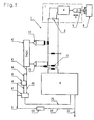
- Fig. 1 is essentially the control and control elements of a general embodiment of the invention in a schematic representation again.
- a conventional, generally designated by the reference numeral 1 oscillatory structure of an electromechanical, preferably piezoelectric converter 2, a mechanically connected to this sonotrode 3 and optionally an intermediate Amplungsentransformations consultancy 4 the sonotrode 3 are placed with a processing surface 5 on a workpiece 6 can, in a known manner to perform a machining operation, in particular a welding operation.
- the vibrating structure 1 is coupled for this purpose with a feed unit, not shown, and mounted by means of this mostly perpendicular to the workpiece surface in the direction of a double arrow v up and down movable in a frame, also not shown.
- the sonotrode 3 and possibly the amplitude transformation piece 4 are arranged so that the oscillatory structure 1 oscillates resonantly at the resonant frequency of the converter 2 at substantially the same frequency.
- the processing surface 5 of the sonotrode 3 oscillates with a factory-set, mechanical vibration amplitude of, for example, 7 microns to 30 microns.
- the distance of the working surface 5 of the converter 2 is chosen so that there is always a vibration of her belly.
- Ultrasonic processing devices of this type are well known (e.g. DE 34 39 776 C2, DE 42 06 584 C2, DE 44 39 470 C1 and DE 297 13 448 U1) and therefore need not be explained in more detail.
- the piezoelectric converter 2 is generally connected to an AC circuit connected to the reference numeral 7 designated ultrasonic generator.
- AC circuit is a specific for the excitation of the converter 2 AC whose frequency of the oscillation frequency of the converter 2 and the sonotrode 3rd and its strength for the mechanical vibration amplitude of the sonotrode 3 is characteristic in the region of the processing surface 5.
- a transformer 12 is connected and a high-frequency signal with the desired Frequency gives off.
- the secondary coil of the transformer 12 is parallel to the converter 2, which can be considered electrically as a capacitance, connected in the AC circuit, wherein the transformer 12 is dimensioned in the embodiment so that its secondary coil is an AC voltage of z. B. generates 600 V eff .
- the AC circuit preferably includes inductively coupled elements, the z. B. at outputs 17 and 18 each provide an electrical state variable. This is z. B. the output 17 is set up to output a signal representing the active current flowing in the AC circuit, while the output 18 is used to deliver the voltage lying on the secondary coil AC voltage.
- the AC circuit with the elements 2 and 12 for energy reasons preferably formed essentially as a resonant circuit
- the manufacturer of the Device is tuned to the resonant frequency of the converter 2 and under Normal conditions with a frequency of about 35 kHz works.
- the AC circuit to be part of a control loop, in addition to the power section 8 contains and is to maintain the preselected oscillation amplitude of the sonotrode 3.
- the measurement of the actual value of the amplitude can be via the measurement of any appropriate size in the AC circuit of the generator 7 done.
- the sonotrode 3 is always set in vibration only when actually a processing cycle is to be performed, d. H. the AC circuit or even the entire control loop is in the breaks between two machining cycles off and on again shortly before the beginning of the next processing cycle.
- z. B the power unit 8 via a line 24, a switch-on and a Line 25 is supplied to a switch-off signal. This means that the control loop after the Turning on starts working.
- the settling time is with z. B. 0.5 sec normally so short that the sonotrode 3 when hitting the workpiece 6, the desired Has oscillation amplitude.
- control loop is through today realized usual microprocessor techniques.
- current in the AC circuit however, in any way, generally known in ultrasonic welding be generated.
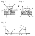
- FIGS. 2 and 3 show schematically details of the sonotrode 3 provided in the exemplary embodiment and suitable for point, rivet or stud welds, which is movable in the direction of an arrow w by means of a feed unit, not shown, and has a processing surface 29.
- the processing surface 29 is formed circular and provided in its center with a protruding pin 30.
- the processing surface 29 is provided with a concave depression, while in an concentric surrounding these and the pin 30, outer region has an annular bearing surface 32 which in the direction of the arrow w against the pin 30 mostly something is behind, but could also easily protrude over the pin 30.
- Fig. 2 and 3 two workpieces to be welded 33 and 34 are also shown.
- the lower workpiece 33 is below when performing a processing cycle the sonotrode 3 z. B. on an anvil, not shown.
- It also exists a thermoplastic material and is on a top in the usual way with a towering, here hollow cylindrical rivet 35 provided.
- the size of the rivet dome 35 of itself consist of any material. It is so on the workpiece before the machining cycle 33 launched that his hole receives the rivet 35 and is penetrated by this.
- the rivet 35 has a length such that it is a pre-selected measure projects beyond the workpiece 34, as shown in FIG. 2.
- a processing cycle is initiated by the sonotrode 3 is moved by means of the feed unit in the direction of the arrow w to approach their work surface 29 to the workpieces 33, 34.
- the arrangement in the exemplary embodiment is such that initially the pin 30 enters the cavity of the rivet mandrel 35 and the sonotrode 3 thereby centered, while subsequently the upper edge of the rivet mandrel 35 comes into contact with the concave heating zone 31.
- a turn-on signal is supplied to the z. B. generated by a feed unit coupled to the switch or any other synchronized with the movement of the feed unit organ.
- the material of the rivet mandrel 35 in contact with its processing zone 31 is gradually melted and taken up in the concave depression upon further downward movement of the sonotrode 3.
- the support surface 32 of the sonotrode 3 finally settles on a surface 36 of the upper workpiece 34 facing it (FIG. 3).
- the material of the rivet mandrel 35 received in the concave depression is thereby deformed into a rivet head 37 (FIG. 3) which bears against the edge of the workpiece 34 which adjoins the hole and thereby connects it to the workpiece 33 in a substantially positive fit.
- the power supply to the converter 2 is turned off and the sonotrode 3 raised again to start a new machining cycle.
- the supply of ultrasonic energy to sonotrode 3 should be interrupted as exactly as possible become when their support surface 32 on the surface 36 of the workpiece 34 hangs up. If the energy supply is interrupted too early, remains between the surface 36 and the rivet head 37 an air gap, the insufficient form or Adhesion of the compound and also an undesirable play between the Workpieces 33, 34 result. If the energy supply to sonotrode 3, however, to turned off late, its support surface 32 in the surface 36 of the workpiece 34th dig in and thereby produce mainly visually unsightly edge zones. this is a Consequence of trying to determine the amplitude of the sonotrode vibration when touchdown the bearing surface 32 on the surface 36 because of the resulting additional load should actually be reduced, via the control circuit To keep substantially constant in FIG. 1, so that the support surface 32 in the same manner as before the heating zone 31 on the material of the workpiece 34th acts and melts this uncontrollably.
- Fig. 4 shows the dependence of the expressed in watts, the converter 2 supplied electrical active power of the time measured in seconds. It is assumed that the power supply is initiated by a turn-on signal in the line 24 at a time t o .
- the active power P then increases during a transient phase, the z. B. about 0.5 sec, along a curve portion 39 initially strong, and then drop at a time t 1 on a curve portion 40 which has a substantially constant height.
- This curve section 40 results when the heating zone 31 of the processing surface 29 of the sonotrode 3 acts on the rivet dome 35 and melts it.
- this is used to generate a switch-off signal.
- the outputs 17 and 18, at which the alternating current I and the Wechelschreib U are tapped, placed on two inputs of a multiplier 42, in which the product P U ⁇ I formed and at one Output 43 is delivered.
- the output 43 is connected on the one hand via a line 44 to a data memory 45, on the other hand via a line 46 to an input of a comparator 47 having a second, connected via a line 48 to an output of the data memory 45 input and one connected to the line 25 Output owns.
- the line 24 is connected via a line 49 to an input of a timer 50 having an output connected via a line 51 to a further input of the data memory 45.
- the power P is constantly being determined. Their respective actual value is supplied to both the data memory 45 and the comparator 47. At the same time causes the timer 50 via line 51, that a preselected period of time from the appearance of the turn-on, z. B. at a time t 4 , on the one hand, the comparator 47 is activated and on the other hand, the data memory 45 at this time t 4 existing value of the active power P firmly takes over and puts on the associated input of the comparator 47. In the further course, the comparator 47 compares the power value stored in the data memory 45 with the respective actual value which is output by the multiplier stage 42.
- the comparator 47 If this value is greater than the value present in the data memory 45 by a preselected amount, the comparator 47 outputs a signal which appears as a switch-off signal in the line 25 and terminates the supply of ultrasound energy to the converter 2. In addition, the power-off signal may be used to reset the device to the initial state and clear the data memory 45.
- the predetermined by the timing 50 preferably adjustable period of time is suitably chosen so large with t 1 ⁇ t 4 ⁇ t 2 as shown in FIG. 4 that the data memory 45 takes a value of the active power P , resulting in the region of the curve section 40 and therefore is characteristic of a time between t 1 and t 2 after completion of a settling time.
- the comparator 47 is set up so that it outputs the switch-off signal in the line 25 when the current actual value of the active power P by a preselected amount is greater than the value stored in the data memory 45 and z. B. at a time t 5 is obtained.
- the comparator 45 z. B. have a threshold associated with its output threshold.
- the time t 5 can follow the time t 2 , in particular very briefly, when the time t 4 lies safely in the curve section 40.
- the time t 5 would have to be selected so that the active power P present then is greater than it can become along the curve section 39 during the transient process.
- the generation of the switch-off can be made taking into account any other appropriate electrical state variable of the generator 7, z. B. taking into account the frequency at the output of the power unit 8 or the phase shift between the current at the output 17 and the voltage at the output 18. The components 42, 45, 47 and 50 would then have to be adapted accordingly.
- the term "taking into account the respective state variable” should be understood to mean that the switch-off signals are generated as a function of which change the state variable after placement of the support surface 32 on the workpiece 34 in comparison to the previous processing during a normal or useful detected processing time undergoes the z. B. is defined by the time interval between t 0 and t 2 in Fig. 4.
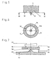
- the support surface 32 according to FIGS. 5 and 6 as large as possible.
- the workpiece should 54 here consist of a comparatively hard material, so that the mechanical Vibrations of the sonotrode 57 do not lead to a melting of its surface 59, but cause the entire workpiece 54 to vibrate with the result that the Energy Vietnamesesgeber 60 melts and thereby lowering the sonotrode 57 the two workpieces 53, 54 welded together.
- Fig. 4 at least one electrical state variable of the ultrasonic generator used at the moment when the two connecting surfaces 55, 56 are adjacent to each other, strongly to or from, so that they are exploited to generate a shutdown signal can. In this case, a timely shutdown of the power supply has the consequence that the sonotrode 57 can not dig into the surface 59 of the workpiece 54.
- the invention is not limited to the described embodiments, which can be modified in many ways.
- a mean value measured from the time t 0 or t 1 could be used and a switch-off signal generated if the mean value changes significantly compared to the normal processing cycle or if the actual value of the state variable deviates significantly from the mean value.
- the power supply after the impact of the sonotrode 3 on the workpiece 34 or the workpiece 54 on the workpiece 53 remains switched on for a preselected time if this is to achieve of a good processing result has proven to be useful.
- the shutdown of the power supply takes place only when the value of the state variable is greater than any value that can occur within a recognized as useful processing time.
- the operations described with reference to FIGS. 2, 4 and 7 and the associated sonotrode shapes are to be understood as examples only. It will also be understood that the described apparatus may include a plurality of sonotrodes, which are lowered in a common operation to a corresponding plurality of processing stations, and a corresponding number of these individually associated circuits 42 to 51.
- the invention can also be applied analogously to spot welding, in which case the preselected contact surface 32 of the sonotrode can be substantially larger in proportion and can practically consist of the entire sonotrode underside.
- the generator 7 and the circuit formed by the elements 42 to 51 may be constructed differently than shown.
Landscapes
- Engineering & Computer Science (AREA)
- Mechanical Engineering (AREA)
- Lining Or Joining Of Plastics Or The Like (AREA)
- Pressure Welding/Diffusion-Bonding (AREA)
- Apparatuses For Generation Of Mechanical Vibrations (AREA)
Claims (10)
- Procédé d'usinage par ultrasons de pièces (33, 34 ; 53, 54) avec une structure vibrante (1) présentant une sonotrode (3, 57) et un convertisseur (2), dans lequel, pour l'exécution de cycles d'usinage, la sonotrode (3, 57) est approchée des pièces (33, 34 ; 53, 54) et à cette occasion pressée contre une des pièces (33, 34 ; 53, 54) de telle manière que les deux pièces (33, 34 ; 53, 54) soient rigidement reliées ensemble par fusion locale de zones présélectionnées (35, 60) et dans lequel on ne fournit de l'énergie ultrasonore au convertisseur (2), au moyen d'un générateur d'ultrasons (7) qui est activé et désactivé par des signaux d'activation et de désactivation électriques, que pendant la durée des cycles d'usinage, caractérisé par le fait que l'usinage est réalisé de telle manière que les cycles d'usinage se terminent sensiblement exactement quand une surface d'appui (32) sélectionnée de la sonotrode (3) et une surface de pièce (36) tournée vers elle ou deux surfaces d'assemblage (55, 56) se faisant face des pièces (53, 54) entrent en contact mutuel, les signaux de désactivation étant générés en tenant compte d'au moins une grandeur d'état électrique (P) du générateur (7) qui subit un changement caractéristique, indiquant le contact, lors du contact mutuel des surfaces (32, 36 ; 55, 56).
- Procédé selon la revendication 1, caractérisé par le fait que l'on utilise comme grandeur d'état électrique la fréquence du courant circulant dans le générateur (7), le déphasage entre le courant et la tension dans le générateur (7) et/ou la puissance ultrasonore électrique (P) générée par le générateur (7).
- Dispositif pour l'usinage par ultrasons de pièces (33, 34 ; 53, 54) comprenant :une structure vibrante (1) avec une sonotrode (3, 57) et un convertisseur électromécanique (2), un générateur (7) relié au convertisseur (2), destiné à l'amenée d'énergie ultrasonore, une unité d'avance pour déplacer la sonotrode (3, 57) pendant des cycles d'usinage en direction des pièces (33, 34 ; 53, 54) jusqu'à la mise en contact mutuel d'une surface d'appui (32) sélectionnée de la sonotrode (3) et d'une surface de pièce (36) tournée vers elle ou deux surfaces d'assemblage (55, 56) se faisant face des pièces (53, 54), des moyens (24, 25) pour générer des signaux d'activation et de désactivation pour le générateur (7) respectivement au début et à la fin des cycles d'usinage, caractérisé par au moins une sortie (17, 18 ou 43) prévue pour délivrer une grandeur d'état électrique (P) sélectionnée du générateur (7), la grandeur d'état électrique étant une grandeur d'état qui change lors du contact mutuel des surfaces (32, 36 ; 55, 56) et les signaux de désactivation pouvant être générés lorsque la grandeur d'état électrique a subi un changement présélectionné.
- Dispositif selon la revendication 3, caractérisé par le fait que la grandeur d'état électrique est la fréquence du courant circulant dans le générateur (7), le déphasage entre le courant et la tension dans le générateur (7) et/ou la puissance active (P) générée par le générateur (7).
- Dispositif selon la revendication 3 ou 4, caractérisé par le fait que la sortie (17, 18 ou 43) prévue pour délivrer la grandeur d'état électrique (P) est reliée à un circuit (44 à 51) destiné à délivrer les signaux de désactivation, qui délivre toujours les signaux de désactivation lorsque la grandeur d'état électrique (P) diffère d'un montant présélectionné de valeurs qu'elle peut prendre pendant une durée d'usinage reconnue comme utile.
- Dispositif selon la revendication 5, caractérisé par le fait que les signaux de désactivation peuvent être générés lorsque la grandeur d'état électrique (P) diffère d'un montant présélectionné d'une valeur moyenne que l'on obtient entre des instants présélectionnés pendant une durée d'usinage reconnue comme utile.
- Dispositif selon la revendication 5 ou 6, caractérisé par le fait que le circuit (44 à 51) ne peut être activé chaque fois qu'un certain temps (t4) présélectionné après apparition des signaux d'activation (t0).
- Dispositif selon l'une des revendications 3 à 7, caractérisé par le fait que lors du soudage par points, de rivets ou de goujons, les signaux de désactivation peuvent être générés à des instants (t5) qui correspondent à la pose de la surface d'appui (32) présélectionnée de la sonotrode (3) sur la surface (36) tournée vers elle d'une pièce (34) associée.
- Dispositif selon l'une des revendications 3 à 7, caractérisé par le fait que lors du soudage plan avec des directeurs d'énergie (60), les signaux de désactivation peuvent être générés à des instants qui correspondent à la mise en contact plan des deux surfaces d'assemblage (55, 56).
- Dispositif selon la revendication 8, caractérisé par le fait que la surface d'appui (32a) de la sonotrode (3) est choisie plus grande que nécessaire au minimum pour la réalisation de l'usinage.
Applications Claiming Priority (2)
| Application Number | Priority Date | Filing Date | Title |
|---|---|---|---|
| DE10046451 | 2000-09-18 | ||
| DE2000146451 DE10046451A1 (de) | 2000-09-18 | 2000-09-18 | Verfahren und Vorrichtung zum Ultraschallschweißen von Werkstücken |
Publications (2)
| Publication Number | Publication Date |
|---|---|
| EP1190804A1 EP1190804A1 (fr) | 2002-03-27 |
| EP1190804B1 true EP1190804B1 (fr) | 2005-08-31 |
Family
ID=7656869
Family Applications (1)
| Application Number | Title | Priority Date | Filing Date |
|---|---|---|---|
| EP20010122191 Expired - Lifetime EP1190804B1 (fr) | 2000-09-18 | 2001-09-17 | Procédé et dispositif de soudage par ultrasons de pièces |
Country Status (4)
| Country | Link |
|---|---|
| US (1) | US6752886B2 (fr) |
| EP (1) | EP1190804B1 (fr) |
| AT (1) | ATE303225T1 (fr) |
| DE (2) | DE10046451A1 (fr) |
Cited By (1)
| Publication number | Priority date | Publication date | Assignee | Title |
|---|---|---|---|---|
| DE102011052283A1 (de) * | 2011-07-29 | 2013-01-31 | Herrmann Ultraschalltechnik Gmbh & Co. Kg | Verfahren zur Berechnung der Schwingungsamplitude einer Sonotrode |
Families Citing this family (24)
| Publication number | Priority date | Publication date | Assignee | Title |
|---|---|---|---|---|
| AU2002347128A1 (en) | 2001-12-24 | 2003-07-15 | Woodwelding Ag | Method for applying elements to surfaces of constructed objects used for road traffic |
| DE10309607B9 (de) * | 2003-03-05 | 2006-12-14 | Osram Opto Semiconductors Gmbh | Verfahren zur Verkapselung von funktionellen Komponenten eines optoelektronischen Bauelements |
| DE102004018309B4 (de) | 2004-04-13 | 2009-01-02 | Maschinenfabrik Spaichingen Gmbh | Vorrichtung zum Stanzen und Schweißen oder Kleben von Werkstücken |
| DK1659286T3 (da) * | 2004-11-18 | 2009-02-23 | Eickhoff Maschinenfabrik Gmbh | Törneindretning til at drive en drivmotor og transmission i et vindkraftanlæg |
| DE102004057453B3 (de) | 2004-11-25 | 2006-04-27 | Maschinenfabrik Spaichingen Gmbh | Verfahren und Vorrichtung zum Verbinden von Gegenständen mittels wenigstens eines plastifizierbaren Verbindungselements |
| JP4792945B2 (ja) * | 2005-01-28 | 2011-10-12 | 日産自動車株式会社 | 超音波接合装置および接合構造体 |
| DE102005009096A1 (de) | 2005-02-22 | 2006-08-24 | Maschinenfabrik Spaichingen Gmbh | Vorrichtung zum Bearbeiten von Kunststoff enthaltenden Werkstücken |
| GB2425179A (en) * | 2005-04-14 | 2006-10-18 | Warwickshire Mfg Group | Assessing the quality of rivets by evaluating the complex valued electrical impedance of a piezoelectric ultrasonic transducer |
| DE102005060026B4 (de) * | 2005-12-14 | 2013-08-29 | Ms Spaichingen Gmbh | Vorrichtung zur Durchführung von Stanz- und/oder Schweiß- und/oder Klebearbeiten |
| US9914263B2 (en) * | 2006-05-08 | 2018-03-13 | Dukane Ias, Llc | Ultrasonic press with automatic speed changes in advancing movement of welding stack |
| DE102007035484A1 (de) | 2007-07-28 | 2009-01-29 | Dr. Ing. H.C. F. Porsche Aktiengesellschaft | Bauteilanordnung |
| DE102008011151A1 (de) * | 2008-02-26 | 2009-08-27 | Maschinenfabrik Spaichingen Gmbh | Verfahren und Vorrichtung zum Verbinden von Gegenständen |
| EP2285520B1 (fr) * | 2008-05-02 | 2019-01-02 | Sonics & Materials Inc. | Système pour empêcher des surcharges pour des applications de rivetage par ultrasons |
| DE102010004468A1 (de) * | 2010-01-13 | 2011-07-14 | Maschinenfabrik Spaichingen GmbH, 78549 | Verfahren und Vorrichtung zur Ultraschallbearbeitung |
| US8425706B2 (en) * | 2010-02-25 | 2013-04-23 | GM Global Technology Operations LLC | Joint design for welding plastic assemblies |
| CN102229022A (zh) * | 2011-06-21 | 2011-11-02 | 西安理工大学 | 超声波辅助亚稳合金快速凝固焊接装置及焊接方法 |
| US9550323B2 (en) * | 2013-09-06 | 2017-01-24 | GM Global Technology Operations LLC | Systems and methods for adaptive process control using a target kinematics profile in welding together multiple polymeric workpieces |
| DE102017107617A1 (de) * | 2017-04-10 | 2018-10-11 | Herrmann Ultraschalltechnik Gmbh & Co. Kg | Verfahren zum intermittierenden Ultraschallbearbeiten einer Materialbahn |
| CN108213688A (zh) * | 2018-02-09 | 2018-06-29 | 中国人民解放军陆军装甲兵学院 | 一种超声振动辅助焊接试验装置 |
| DE102019109262B4 (de) * | 2019-04-09 | 2025-11-20 | Lisa Dräxlmaier GmbH | VORRICHTUNG UND VERFAHREN ZUM BESTIMMEN EINES ZUSTANDS EINES ULTRASCHALLSCHWEIßPROZESSES |
| FR3102943B1 (fr) * | 2019-11-07 | 2021-10-15 | Faurecia Interieur Ind | Pièce de véhicule destinée à être soudée par ultrasons, ensembles comprenant une telle pièce et procédé de soudage par ultrasons d’une telle pièce |
| DE102020200184A1 (de) * | 2020-01-09 | 2021-07-15 | Magna Exteriors (Bohemia) s.r.o. | Verfahren zum Ultraschallverschweißen zweier Kunststoffkomponenten und dadurch hergestellte Kunststoffbauteile |
| CN111823601B (zh) * | 2020-06-11 | 2026-03-20 | 厦门建霖健康家居股份有限公司 | 一种降低工程塑料超声波焊接难度的方法 |
| CN113909577A (zh) * | 2021-10-12 | 2022-01-11 | 科益展智能装备有限公司 | 超声波加工装置及其控制方法 |
Family Cites Families (14)
| Publication number | Priority date | Publication date | Assignee | Title |
|---|---|---|---|---|
| US3784079A (en) | 1972-04-03 | 1974-01-08 | Motorola Inc | Ultrasonic bond control apparatus |
| US4341574A (en) | 1980-08-25 | 1982-07-27 | Texas Instruments Incorporated | Ultrasonic bond energy monitor |
| DD154343A1 (de) | 1980-12-22 | 1982-03-17 | Wolfgang Klimes | Verfahren zur begrenzung der auf das werkstueck uebertragenen schweissenergie beim ultraschallplastfuegen |
| US4746051A (en) * | 1982-12-08 | 1988-05-24 | General Motors Corporation | Ultrasonic welding control |
| DE3429776A1 (de) | 1984-08-13 | 1986-02-13 | Siemens AG, 1000 Berlin und 8000 München | Verfahren zur qualitaetskontrolle beim ultraschallschweissen sowie zugehoerige vorrichtung |
| SU1315341A1 (ru) | 1985-06-12 | 1987-06-07 | Всесоюзный научно-исследовательский проектно-конструкторский и технологический институт токов высокой частоты им.В.П.Вологдина | Способ регулировани ультразвуковой сварки термопластичных материалов |
| SE451972B (sv) * | 1985-06-28 | 1987-11-09 | Tetra Pak Ab | Sett och anordning for att reglera energitillforseln till ett ultraljudforseglingsdon |
| US4865687A (en) * | 1988-12-23 | 1989-09-12 | Eastman Kodak Company | Ultrasonic securing method |
| DE4206584C2 (de) | 1992-03-03 | 1994-03-10 | Fraunhofer Ges Forschung | Vorrichtung und Verfahren zum Verbinden zweier Bauteile mittels Ultraschall |
| DE567426T1 (de) * | 1992-04-21 | 1994-02-03 | Emerson Electric Co | Verfahren und Gerät zur Werkstückbearbeitung mit Ultraschallenergie. |
| US5855706A (en) * | 1992-04-21 | 1999-01-05 | Branson Ultrasonics Corporation | Simultaneous amplitude and force profiling during ultrasonic welding of thermoplastic workpieces |
| US5658408A (en) * | 1992-04-21 | 1997-08-19 | Branson Ultrasonics Corporation | Method for processing workpieces by ultrasonic energy |
| DE4439470C2 (de) | 1994-11-08 | 1999-05-20 | Herrmann Ultraschalltechnik | Vorrichtung zum Ultraschallbearbeiten eines Werkstücks |
| DE29713448U1 (de) | 1997-07-29 | 1997-10-23 | Spaichingen Gmbh Maschf | Vorrichtung zur Ultraschallbearbeitung von Werkstücken |
-
2000
- 2000-09-18 DE DE2000146451 patent/DE10046451A1/de not_active Withdrawn
-
2001
- 2001-09-17 US US09/954,584 patent/US6752886B2/en not_active Expired - Lifetime
- 2001-09-17 DE DE50107261T patent/DE50107261D1/de not_active Expired - Lifetime
- 2001-09-17 AT AT01122191T patent/ATE303225T1/de not_active IP Right Cessation
- 2001-09-17 EP EP20010122191 patent/EP1190804B1/fr not_active Expired - Lifetime
Cited By (1)
| Publication number | Priority date | Publication date | Assignee | Title |
|---|---|---|---|---|
| DE102011052283A1 (de) * | 2011-07-29 | 2013-01-31 | Herrmann Ultraschalltechnik Gmbh & Co. Kg | Verfahren zur Berechnung der Schwingungsamplitude einer Sonotrode |
Also Published As
| Publication number | Publication date |
|---|---|
| US6752886B2 (en) | 2004-06-22 |
| DE10046451A1 (de) | 2002-03-28 |
| ATE303225T1 (de) | 2005-09-15 |
| EP1190804A1 (fr) | 2002-03-27 |
| US20020100534A1 (en) | 2002-08-01 |
| DE50107261D1 (de) | 2005-10-06 |
Similar Documents
| Publication | Publication Date | Title |
|---|---|---|
| EP1190804B1 (fr) | Procédé et dispositif de soudage par ultrasons de pièces | |
| DE69307179T2 (de) | Ultraschallschweissverfahren | |
| DE102009023853B4 (de) | Widerstandsschweißverfahren und geschweißte Struktur | |
| EP1812200A1 (fr) | Dispositif pour la mise en oeuvre d'un procede de traitement de surface, d'assemblage ou de separation, en particulier d'un procede de soudage | |
| EP3030373B1 (fr) | Procédé et dispositif de soudage par résistance de tôles sandwich | |
| EP0340671A2 (fr) | Procédé et appareil pour la commande des paramètres d'une machine de soudage par friction | |
| EP0421019A1 (fr) | Méthode et dispositif de jointure d'éléments en matière plastique par ultrasons | |
| WO2014173472A1 (fr) | Appareil de placement et de soudage, composants modulaires dudit appareil et procédé d'assemblage en continu pouvant être mis en œuvre au moyen dudit appareil | |
| EP1418016A2 (fr) | Appareil de soudace à l'arc électrique, procédé pour souder des tôles à des pièces correspondantes métalliques et élément de soudage | |
| EP0208310A1 (fr) | Méthode pour régler le déroulement du processus et pour le contrôle de la qualité pour le soudage à ultrasons de pièces d'ouvrage | |
| DE4321874A1 (de) | Verfahren und Vorrichtung zum Steuern und Regeln von Prozeßparametern beim Ultraschallschweißen | |
| CH671355A5 (fr) | ||
| DE3933982C2 (de) | Kontaktierungsverfahren und Kontaktierungsvorrichtung | |
| EP2085161A1 (fr) | Procédé et dispositif d'enlèvement de creux d'une structure électrique conductrice et plate en vue de la formation d'une structure lisse | |
| EP2058109A2 (fr) | Dispositif de soudure à ultrasons | |
| DE102004051389B4 (de) | Verfahren und System zum Verschweißen eines eine kegelartige Stirnfläche aufweisenden Bolzens mit einem Träger | |
| EP1714771A2 (fr) | Procédé et dispositif pour souder deux pièces thermoplastiques par soudage laser | |
| DE3635946A1 (de) | Verfahren und vorrichtung zum warzenschweissen | |
| DE19955691C2 (de) | Verfahren und Vorrichtung zum Widerstandsschweissen | |
| WO2017216104A1 (fr) | Dispositif et procédé de sertissage d'éléments de liaison et liaison par sertissage | |
| DE102011018653A1 (de) | Widerstands-Schweißvorrichtung | |
| EP0611643A1 (fr) | Procédé pour la fabrication de joints soudés par joints ou par petites surfaces avec au moins deux couches en matière thermoplastique qui sont l'une sur l'autre ou qui s'approchent l'une de l'autre | |
| DE3342619A1 (de) | Verfahren und maschine zum ultraschallschweissen von thermoplastischen kunststoffteilen | |
| EP0196584A1 (fr) | Dispositif servant à raccorder, en particulier des conducteurs électriques | |
| DE4328391C2 (de) | Verfahren und Vorrichtung zum Verschweißen von Kunststoffprofilen |
Legal Events
| Date | Code | Title | Description |
|---|---|---|---|
| PUAI | Public reference made under article 153(3) epc to a published international application that has entered the european phase |
Free format text: ORIGINAL CODE: 0009012 |
|
| AK | Designated contracting states |
Kind code of ref document: A1 Designated state(s): AT BE CH CY DE DK ES FI FR GB GR IE IT LI LU MC NL PT SE TR |
|
| AX | Request for extension of the european patent |
Free format text: AL;LT;LV;MK;RO;SI |
|
| 17P | Request for examination filed |
Effective date: 20020824 |
|
| 17Q | First examination report despatched |
Effective date: 20021023 |
|
| AKX | Designation fees paid |
Free format text: AT BE CH CY DE DK ES FI FR GB GR IE IT LI LU MC NL PT SE TR |
|
| GRAP | Despatch of communication of intention to grant a patent |
Free format text: ORIGINAL CODE: EPIDOSNIGR1 |
|
| GRAS | Grant fee paid |
Free format text: ORIGINAL CODE: EPIDOSNIGR3 |
|
| GRAA | (expected) grant |
Free format text: ORIGINAL CODE: 0009210 |
|
| AK | Designated contracting states |
Kind code of ref document: B1 Designated state(s): AT BE CH CY DE DK ES FI FR GB GR IE IT LI LU MC NL PT SE TR |
|
| PG25 | Lapsed in a contracting state [announced via postgrant information from national office to epo] |
Ref country code: FI Free format text: LAPSE BECAUSE OF FAILURE TO SUBMIT A TRANSLATION OF THE DESCRIPTION OR TO PAY THE FEE WITHIN THE PRESCRIBED TIME-LIMIT Effective date: 20050831 Ref country code: TR Free format text: LAPSE BECAUSE OF FAILURE TO SUBMIT A TRANSLATION OF THE DESCRIPTION OR TO PAY THE FEE WITHIN THE PRESCRIBED TIME-LIMIT Effective date: 20050831 Ref country code: NL Free format text: LAPSE BECAUSE OF FAILURE TO SUBMIT A TRANSLATION OF THE DESCRIPTION OR TO PAY THE FEE WITHIN THE PRESCRIBED TIME-LIMIT Effective date: 20050831 Ref country code: IE Free format text: LAPSE BECAUSE OF FAILURE TO SUBMIT A TRANSLATION OF THE DESCRIPTION OR TO PAY THE FEE WITHIN THE PRESCRIBED TIME-LIMIT Effective date: 20050831 |
|
| REG | Reference to a national code |
Ref country code: CH Ref legal event code: EP Ref country code: GB Ref legal event code: FG4D Free format text: NOT ENGLISH |
|
| PG25 | Lapsed in a contracting state [announced via postgrant information from national office to epo] |
Ref country code: CY Free format text: LAPSE BECAUSE OF FAILURE TO SUBMIT A TRANSLATION OF THE DESCRIPTION OR TO PAY THE FEE WITHIN THE PRESCRIBED TIME-LIMIT Effective date: 20050917 Ref country code: AT Free format text: LAPSE BECAUSE OF NON-PAYMENT OF DUE FEES Effective date: 20050917 |
|
| REG | Reference to a national code |
Ref country code: IE Ref legal event code: FG4D Free format text: LANGUAGE OF EP DOCUMENT: GERMAN |
|
| PG25 | Lapsed in a contracting state [announced via postgrant information from national office to epo] |
Ref country code: CH Free format text: LAPSE BECAUSE OF NON-PAYMENT OF DUE FEES Effective date: 20050930 Ref country code: BE Free format text: LAPSE BECAUSE OF NON-PAYMENT OF DUE FEES Effective date: 20050930 Ref country code: LI Free format text: LAPSE BECAUSE OF NON-PAYMENT OF DUE FEES Effective date: 20050930 Ref country code: MC Free format text: LAPSE BECAUSE OF NON-PAYMENT OF DUE FEES Effective date: 20050930 |
|
| REF | Corresponds to: |
Ref document number: 50107261 Country of ref document: DE Date of ref document: 20051006 Kind code of ref document: P |
|
| PGFP | Annual fee paid to national office [announced via postgrant information from national office to epo] |
Ref country code: FR Payment date: 20051024 Year of fee payment: 5 |
|
| PG25 | Lapsed in a contracting state [announced via postgrant information from national office to epo] |
Ref country code: LU Free format text: LAPSE BECAUSE OF NON-PAYMENT OF DUE FEES Effective date: 20051031 |
|
| PGFP | Annual fee paid to national office [announced via postgrant information from national office to epo] |
Ref country code: GB Payment date: 20051109 Year of fee payment: 5 |
|
| PG25 | Lapsed in a contracting state [announced via postgrant information from national office to epo] |
Ref country code: GR Free format text: LAPSE BECAUSE OF FAILURE TO SUBMIT A TRANSLATION OF THE DESCRIPTION OR TO PAY THE FEE WITHIN THE PRESCRIBED TIME-LIMIT Effective date: 20051130 Ref country code: DK Free format text: LAPSE BECAUSE OF FAILURE TO SUBMIT A TRANSLATION OF THE DESCRIPTION OR TO PAY THE FEE WITHIN THE PRESCRIBED TIME-LIMIT Effective date: 20051130 Ref country code: SE Free format text: LAPSE BECAUSE OF FAILURE TO SUBMIT A TRANSLATION OF THE DESCRIPTION OR TO PAY THE FEE WITHIN THE PRESCRIBED TIME-LIMIT Effective date: 20051130 |
|
| PG25 | Lapsed in a contracting state [announced via postgrant information from national office to epo] |
Ref country code: ES Free format text: LAPSE BECAUSE OF FAILURE TO SUBMIT A TRANSLATION OF THE DESCRIPTION OR TO PAY THE FEE WITHIN THE PRESCRIBED TIME-LIMIT Effective date: 20051212 |
|
| GBT | Gb: translation of ep patent filed (gb section 77(6)(a)/1977) |
Effective date: 20051130 |
|
| PG25 | Lapsed in a contracting state [announced via postgrant information from national office to epo] |
Ref country code: PT Free format text: LAPSE BECAUSE OF FAILURE TO SUBMIT A TRANSLATION OF THE DESCRIPTION OR TO PAY THE FEE WITHIN THE PRESCRIBED TIME-LIMIT Effective date: 20060222 |
|
| NLV1 | Nl: lapsed or annulled due to failure to fulfill the requirements of art. 29p and 29m of the patents act | ||
| REG | Reference to a national code |
Ref country code: IE Ref legal event code: FD4D |
|
| REG | Reference to a national code |
Ref country code: CH Ref legal event code: PL |
|
| ET | Fr: translation filed | ||
| PLBE | No opposition filed within time limit |
Free format text: ORIGINAL CODE: 0009261 |
|
| STAA | Information on the status of an ep patent application or granted ep patent |
Free format text: STATUS: NO OPPOSITION FILED WITHIN TIME LIMIT |
|
| 26N | No opposition filed |
Effective date: 20060601 |
|
| PGFP | Annual fee paid to national office [announced via postgrant information from national office to epo] |
Ref country code: IT Payment date: 20060930 Year of fee payment: 6 |
|
| GBPC | Gb: european patent ceased through non-payment of renewal fee |
Effective date: 20060917 |
|
| REG | Reference to a national code |
Ref country code: FR Ref legal event code: ST Effective date: 20070531 |
|
| PG25 | Lapsed in a contracting state [announced via postgrant information from national office to epo] |
Ref country code: GB Free format text: LAPSE BECAUSE OF NON-PAYMENT OF DUE FEES Effective date: 20060917 |
|
| BERE | Be: lapsed |
Owner name: MASCHINENFABRIK SPAICHINGEN G.M.B.H. Effective date: 20050930 |
|
| PG25 | Lapsed in a contracting state [announced via postgrant information from national office to epo] |
Ref country code: FR Free format text: LAPSE BECAUSE OF NON-PAYMENT OF DUE FEES Effective date: 20061002 |
|
| PG25 | Lapsed in a contracting state [announced via postgrant information from national office to epo] |
Ref country code: IT Free format text: LAPSE BECAUSE OF NON-PAYMENT OF DUE FEES Effective date: 20070917 |
|
| REG | Reference to a national code |
Ref country code: DE Ref legal event code: R082 Ref document number: 50107261 Country of ref document: DE Representative=s name: MANITZ, FINSTERWALD & PARTNER GBR, DE |
|
| REG | Reference to a national code |
Ref country code: DE Ref legal event code: R082 Ref document number: 50107261 Country of ref document: DE Representative=s name: MANITZ FINSTERWALD PATENTANWAELTE PARTMBB, DE Effective date: 20121219 Ref country code: DE Ref legal event code: R081 Ref document number: 50107261 Country of ref document: DE Owner name: MS SPAICHINGEN GMBH, DE Free format text: FORMER OWNER: MASCHINENFABRIK SPAICHINGEN GMBH, 78549 SPAICHINGEN, DE Effective date: 20121219 Ref country code: DE Ref legal event code: R082 Ref document number: 50107261 Country of ref document: DE Representative=s name: MANITZ, FINSTERWALD & PARTNER GBR, DE Effective date: 20121219 |
|
| PGFP | Annual fee paid to national office [announced via postgrant information from national office to epo] |
Ref country code: DE Payment date: 20161129 Year of fee payment: 16 |
|
| REG | Reference to a national code |
Ref country code: DE Ref legal event code: R119 Ref document number: 50107261 Country of ref document: DE |
|
| PG25 | Lapsed in a contracting state [announced via postgrant information from national office to epo] |
Ref country code: DE Free format text: LAPSE BECAUSE OF NON-PAYMENT OF DUE FEES Effective date: 20180404 |