EP1190883A2 - Agencement d'un radiateur - Google Patents
Agencement d'un radiateur Download PDFInfo
- Publication number
- EP1190883A2 EP1190883A2 EP01203336A EP01203336A EP1190883A2 EP 1190883 A2 EP1190883 A2 EP 1190883A2 EP 01203336 A EP01203336 A EP 01203336A EP 01203336 A EP01203336 A EP 01203336A EP 1190883 A2 EP1190883 A2 EP 1190883A2
- Authority
- EP
- European Patent Office
- Prior art keywords
- radiator
- bore
- collar
- support member
- spring clip
- Prior art date
- Legal status (The legal status is an assumption and is not a legal conclusion. Google has not performed a legal analysis and makes no representation as to the accuracy of the status listed.)
- Granted
Links
- 238000000034 method Methods 0.000 claims abstract description 11
- 238000003780 insertion Methods 0.000 claims abstract description 9
- 230000037431 insertion Effects 0.000 claims abstract description 8
- 238000010068 moulding (rubber) Methods 0.000 claims description 13
- 238000009434 installation Methods 0.000 claims description 2
- 238000000465 moulding Methods 0.000 description 6
- 229920001971 elastomer Polymers 0.000 description 3
- 230000005540 biological transmission Effects 0.000 description 2
- 230000006835 compression Effects 0.000 description 2
- 238000007906 compression Methods 0.000 description 2
- 238000001816 cooling Methods 0.000 description 2
- 238000013016 damping Methods 0.000 description 2
- 239000002184 metal Substances 0.000 description 2
- 230000035939 shock Effects 0.000 description 2
- 230000000694 effects Effects 0.000 description 1
- 239000000806 elastomer Substances 0.000 description 1
- 230000000116 mitigating effect Effects 0.000 description 1
- 238000012986 modification Methods 0.000 description 1
- 230000004048 modification Effects 0.000 description 1
- 238000004073 vulcanization Methods 0.000 description 1
Images

Classifications
-
- B—PERFORMING OPERATIONS; TRANSPORTING
- B62—LAND VEHICLES FOR TRAVELLING OTHERWISE THAN ON RAILS
- B62D—MOTOR VEHICLES; TRAILERS
- B62D25/00—Superstructure or monocoque structure sub-units; Parts or details thereof not otherwise provided for
- B62D25/08—Front or rear portions
- B62D25/082—Engine compartments
- B62D25/084—Radiator supports
-
- B—PERFORMING OPERATIONS; TRANSPORTING
- B60—VEHICLES IN GENERAL
- B60K—ARRANGEMENT OR MOUNTING OF PROPULSION UNITS OR OF TRANSMISSIONS IN VEHICLES; ARRANGEMENT OR MOUNTING OF PLURAL DIVERSE PRIME-MOVERS IN VEHICLES; AUXILIARY DRIVES FOR VEHICLES; INSTRUMENTATION OR DASHBOARDS FOR VEHICLES; ARRANGEMENTS IN CONNECTION WITH COOLING, AIR INTAKE, GAS EXHAUST OR FUEL SUPPLY OF PROPULSION UNITS IN VEHICLES
- B60K11/00—Arrangement in connection with cooling of propulsion units
- B60K11/02—Arrangement in connection with cooling of propulsion units with liquid cooling
- B60K11/04—Arrangement or mounting of radiators, radiator shutters, or radiator blinds
-
- B—PERFORMING OPERATIONS; TRANSPORTING
- B62—LAND VEHICLES FOR TRAVELLING OTHERWISE THAN ON RAILS
- B62D—MOTOR VEHICLES; TRAILERS
- B62D27/00—Connections between superstructure or understructure sub-units
- B62D27/04—Connections between superstructure or understructure sub-units resilient
Definitions
- the present invention relates to the mounting of a radiator on the chassis of a vehicle and is particularly applicable to vehicles, such as tractors, where access to the opposite side of the support member onto which the radiator is to be mounted is restricted.
- the chassis in a tractor is commonly formed by the engine block and transmission housing.
- a bolster or front support member is secured to the front end of the engine and forms a structural part of the chassis which projects forward of the engine block. This bolster may be used to attach an implement to the front end of the tractor and often carries heavy blocks to weigh down the front end of the tractor.
- the bolster is also used to support the radiator of the engine cooling system.
- bores are provided in the bolster and the radiator is secured by means of bolts that are screwed from the underside of the bolster into legs of the radiator.
- a difficulty encountered in mounting a radiator in this manner is caused by the fact that the bolster is located above the front axle of the tractor. Access to its underside, to allow the bolts to be screwed into the radiator legs, is severely restricted by the front axle and this precludes the use of power tools. As a result, mounting the radiator on its support member in a tractor has hitherto proved to be a cumbersome and time consuming task.
- the present invention provides in accordance with a first aspect, a method of mounting a radiator onto a support member in a vehicle, which comprises the steps of securing to the radiator a collar having a reduced diameter portion or a groove that defines a shoulder facing towards the radiator, providing a groove or reduced diameter portion in the inner surface of a radiator mounting bore formed in the support member to define a second shoulder facing away from the radiator, positioning a spring clip against one of the shoulders on the collar and the bore and inserting the collar into the bore, the spring clip being compressed radially during insertion of the collar into the bore and being released after full insertion of the collar into the bore to abut both shoulders and prevent withdrawal of the collar from the bore.
- the invention proposes mounting a radiator on the support member using a locking mechanism analogous to those adopted in security seals that are used to prevent tampering with shipping containers and trailers.
- Such seals one example of which is described in US-A-5.005.883, have a metal bolt which can be inserted into a lock body and once so inserted cannot be separated from the lock body.
- the bore in the lock body has an internal groove within which there sits a spring clip.
- the end of the bolt is tapered so that as it is inserted into the lock body, the spring clip expands into the groove and does not impede insertion of the bolt.
- the bolt also has a groove on its outer surface which on reaching the spring clip releases compression forces on the latter. The spring clip then expands and prevents withdrawal of the bolt from the lock body.
- This form of secure fixing is used in the present invention to allow a radiator to be mounted on its support member by assembling retaining collars on the legs or mounting points of the radiator and then pushing the collars into the bores in the support member until the spring clips engage.
- This simple operation does not require access to the opposite side of the support member for the purpose of assembling the radiator on the support member.
- both shoulders are defined by grooves only slightly wider than the spring clip as this allows the spring clip to prevent movement of the radiator in both directions.
- the radiator cannot be pulled away from the support member, if the retaining collar is bolted onto the radiator then the radiator can be removed from the support member by unbolting the collar from the radiator. This allows the radiator to be separated from the support member while leaving the collar in place. Such removal would require tool access to the opposite side of the support member.
- a method of mounting a radiator onto a support member in a vehicle comprising the steps of securing to the radiator a resilient mounting bush having a first annular groove in its outer surface, providing a second annular groove in the inner surface of a radiator mounting bore formed in the support member, positioning a spring clip in one of the two annular grooves and inserting the bush into the bore, the spring clip being compressed radially during insertion of the bush into the bore and being released when the annular grooves are axially aligned with one another to lock the bush within the bore.
- the mounting collar forms part of a resilient mounting bush serving to absorb shocks and vibrations.
- Resilient mounts and bushes have been used to support radiators on vehicle bodies and examples of such mounts are shown for example in US-A-4.519.467 or US-A-5.785.140.
- the invention succeeds in combining the advantages of a resilient mounting with ease of assembly and mounting.
- a vehicle having a radiator mounted on a support member, wherein the radiator is fitted with a retaining collar having a first annular groove in its outer surface, the support member has a radiator mounting bore within which the retaining collar is received, the wall of which mounting bore is formed with a second annular groove, and a spring clip engages within both grooves to prevent the radiator from being separated from the support member.
- the collar is the outer collar of a resilient bush which additionally comprises an inner sleeve and a rubber moulding separating the inner sleeve from the outer collar.
- the rubber moulding is preferably shaped to make direct contact additionally with the radiator body and the wall of the bore in the support member. It is further preferred to interpose a washer between the end of the inner sleeve and the head of a bolt or a nut serving to secure the retaining collar to the radiator and to shape the rubber moulding to make direct contact with the washer.
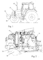
- FIGS 1 and 2 show the manner in which a radiator 10 is mounted in a tractor 12.
- the chassis of the tractor 12 is formed by the engine block 14 and transmission housing.
- a bolster or front support member 16 is secured to the front end of the engine block 14 and forms a structural part of the chassis which projects forward of the engine block 14. This bolster 16 may be used to attach an implement to the front end of the tractor 12 and often carries heavy blocks 18 to weigh down the front end of the tractor 12.
- the bolster 16 is also used to support the radiator 10 of the engine cooling system.
- bores are provided in the bolster 16 and conventionally the radiator would be secured by means of bolts that are screwed from the underside of the bolster into legs of the radiator 10.
- a difficulty encountered in mounting a radiator in this conventional manner is caused by the fact that the bolster 16 is located above the front axle 20 of the tractor. Access to its underside, to allow the bolts to be screwed into the radiator legs, is severely restricted by the front axle 20 and this precludes the use of power tools. As a result, mounting the radiator on the bolster 16 in a tractor 10 has hitherto proved to be a cumbersome and time consuming task.
- the invention provides a mounting that allows the radiator 10 to be dropped into position from above.
- the mounting of the preferred embodiment of the invention is shown within the frame drawn in dotted lines in Figure 2, this part of the drawing being shown to a much enlarged scale in Figure 3.
- FIG 3 shows just one leg 50 of the radiator 10 mounted in a bore 52 in the bolster 16.
- the radiator has two (or more) legs 50, each of which is formed by a U-shaped bracket welded to the lower tank of the radiator 10 and has a nut 54 welded to the upper surface of the base 56 of the bracket.
- a mounting bush 60 is fitted to each leg 10 of the radiator before it is introduced into the bolster 16.
- the bush 60 comprises a central metal sleeve 62 and an outer retaining collar 64 separated from one another by a rubber moulding 66 which acts to absorb shocks and prevent vibrations.
- the bush is secured to the leg 50 by means of a bolt 70 and a washer 72.
- the outer retaining collar 64 is formed with a circumferential groove 68 within which there is placed a spring clip 74.
- the natural outer diameter of the spring clip 74 is greater than that of the narrower section of bore 52 and its inner diameter is smaller than the outer diameter of the collar 64.
- the clip 74 is not continuous around the circumference of the collar 64 but can be compressed to lie entirely within the annular groove 68 surrounding the collar 64.
- the bores 52 have a conically tapering mouth which has the effect of compressing the spring clip 74 as the bush 60 is lowered in the bore 52.
- the tapering mouth ends in a cylindrical, lower portion provided with a further annular groove.
- the bush 60 continues to penetrate into the bore 52 until the groove 68 in the collar 64 becomes axially aligned with the corresponding groove in the wall of the bore 52. At this point, the clip 16 springs out into the position shown in Figure 3 and prevents the retaining collar 64 from being withdrawn from the bore 52.
- the rubber moulding 66 could be a cylindrical body sandwiched between the inner sleeve 62 and the outer collar 64 of the bush 60, it is preferred to form it in the manner illustrated in Figure 4.
- the rubber moulding is shown in its compressed state and a relaxed state is shown in dotted lines to indicate the manner in which it is compressed after the bush 60 has been inserted in the bore 52.
- the direct contact of the moulding 66 with the bore 52 reduces noise and vibration by restricting relative movement between the bush 60 and the bolster 16. This contact also restricts the movement of the retaining collar 64, thus allowing the width of the groove within the bore 52 to be large or to be formed only by one shoulder. Lastly, the contact of the moulding with the bore 52 provides additional resistance as the radiator, with its bushes attached, is pushed into the bores 52 in the bolster 16.
- the rubber moulding additionally makes contact with the washer 72 to provide rebound damping.
- the washer 72 also serves to prevent the radiator 10 from separating from the bolster 16 if the rubber moulding should fail.
- the bush 60 is made by placing a retaining collar 64 and a conically tapering sleeve 62 within a die, the cavity of which is then filled with a suitable elastomer, for example a vulcanised rubber of type M170-60.
- a suitable elastomer for example a vulcanised rubber of type M170-60.
- the vulcanisation process bonds the moulding 66 to the two parts 62 and 64 to form a unitary bush 60.
Landscapes
- Engineering & Computer Science (AREA)
- Chemical & Material Sciences (AREA)
- Combustion & Propulsion (AREA)
- Transportation (AREA)
- Mechanical Engineering (AREA)
- Cooling, Air Intake And Gas Exhaust, And Fuel Tank Arrangements In Propulsion Units (AREA)
- Cooling Or The Like Of Semiconductors Or Solid State Devices (AREA)
- Led Device Packages (AREA)
Applications Claiming Priority (2)
| Application Number | Priority Date | Filing Date | Title |
|---|---|---|---|
| GB0023521 | 2000-09-26 | ||
| GB0023521A GB2367042A (en) | 2000-09-26 | 2000-09-26 | Radiator mounting |
Publications (3)
| Publication Number | Publication Date |
|---|---|
| EP1190883A2 true EP1190883A2 (fr) | 2002-03-27 |
| EP1190883A3 EP1190883A3 (fr) | 2005-11-02 |
| EP1190883B1 EP1190883B1 (fr) | 2009-05-20 |
Family
ID=9900114
Family Applications (1)
| Application Number | Title | Priority Date | Filing Date |
|---|---|---|---|
| EP01203336A Expired - Lifetime EP1190883B1 (fr) | 2000-09-26 | 2001-09-04 | Véhicule automobile et procédé de fixation pour le montage d'un radiateur de véhicule automobile |
Country Status (5)
| Country | Link |
|---|---|
| US (1) | US6550558B2 (fr) |
| EP (1) | EP1190883B1 (fr) |
| AT (1) | ATE431793T1 (fr) |
| DE (1) | DE60138745D1 (fr) |
| GB (1) | GB2367042A (fr) |
Cited By (2)
| Publication number | Priority date | Publication date | Assignee | Title |
|---|---|---|---|---|
| FR2864817A1 (fr) * | 2004-01-07 | 2005-07-08 | Zahnradfabrik Friedrichshafen | Dispositif pour fixer une piece sur une carrosserie |
| US20220063395A1 (en) * | 2020-08-31 | 2022-03-03 | Toyota Jidosha Kabushiki Kaisha | Vehicle |
Families Citing this family (19)
| Publication number | Priority date | Publication date | Assignee | Title |
|---|---|---|---|---|
| JP3401489B2 (ja) * | 2000-08-30 | 2003-04-28 | 川崎重工業株式会社 | エンジンのラジエター装置 |
| KR100506646B1 (ko) * | 2002-07-22 | 2005-08-03 | 현대모비스 주식회사 | 차량 라디에이터 상부 마운팅 구조 |
| DE10359357A1 (de) * | 2003-12-16 | 2005-07-28 | Behr Gmbh & Co. Kg | Anordnung zur Befestigung eines Wärmeübertragers, insbesondere eines Kühlmoduls in einem Kraftfahrzeug |
| JP4270502B2 (ja) * | 2004-02-13 | 2009-06-03 | 東海ゴム工業株式会社 | エンジンマウント |
| JP2006096164A (ja) * | 2004-09-29 | 2006-04-13 | Honda Motor Co Ltd | 鞍乗型車両の車体フレーム |
| CN101825139B (zh) * | 2009-03-07 | 2013-02-20 | 深圳富泰宏精密工业有限公司 | 铰链筒及应用该铰链筒的便携式电子装置 |
| US8235155B2 (en) * | 2009-06-02 | 2012-08-07 | Deere & Company | Radiator mounting arrangement on utility vehicle |
| US10048023B2 (en) * | 2015-08-27 | 2018-08-14 | Denso International America, Inc. | Heat exchanger shroud mount |
| US10545002B2 (en) | 2016-04-10 | 2020-01-28 | Forum Us, Inc. | Method for monitoring a heat exchanger unit |
| US10514205B2 (en) | 2016-04-10 | 2019-12-24 | Forum Us, Inc. | Heat exchanger unit |
| US10502597B2 (en) | 2016-04-10 | 2019-12-10 | Forum Us, Inc. | Monitored heat exchanger system |
| US10520220B2 (en) * | 2016-04-10 | 2019-12-31 | Forum Us, Inc. | Heat exchanger unit |
| US10533881B2 (en) | 2016-04-10 | 2020-01-14 | Forum Us, Inc. | Airflow sensor assembly for monitored heat exchanger system |
| US10882378B2 (en) * | 2017-08-18 | 2021-01-05 | Zhejiang CFMOTO Power Co., Ltd. | ATV air heat exchanger with mounting structure and linkage |
| US20190145719A1 (en) * | 2017-11-14 | 2019-05-16 | Valeo North America, Inc. | Exchanger frame and core assembly of a motor vehicle and methods of use thereof |
| EP3546264B1 (fr) * | 2018-03-28 | 2020-09-16 | Cikautxo, S. Coop. | Support de radiateur |
| US11098962B2 (en) | 2019-02-22 | 2021-08-24 | Forum Us, Inc. | Finless heat exchanger apparatus and methods |
| US11946667B2 (en) | 2019-06-18 | 2024-04-02 | Forum Us, Inc. | Noise suppresion vertical curtain apparatus for heat exchanger units |
| CN115875121B (zh) * | 2022-12-14 | 2023-07-14 | 江苏科力普汽车部件有限公司 | 一种具有防护结构的拖拉机用散热器 |
Family Cites Families (22)
| Publication number | Priority date | Publication date | Assignee | Title |
|---|---|---|---|---|
| FR2226032A5 (fr) * | 1973-04-11 | 1974-11-08 | Chausson Usines Sa | |
| US3929201A (en) * | 1974-03-01 | 1975-12-30 | Gen Motors Corp | Radiator mountings for internal combustion engines |
| DE2553254C2 (de) * | 1975-11-27 | 1982-11-04 | Daimler-Benz Ag, 7000 Stuttgart | Kühler, insbesondere für Kraftfahrzeuge |
| DE2557967C3 (de) * | 1975-12-22 | 1978-12-14 | Daimler-Benz Ag, 7000 Stuttgart | Kühlerbefestigung eines Kraftfahrzeuges |
| JPS5784223A (en) * | 1980-11-13 | 1982-05-26 | Nissan Motor Co Ltd | Vibration absorber of vehicle |
| JPS6011317B2 (ja) * | 1982-07-10 | 1985-03-25 | トヨタ自動車株式会社 | ラジエ−タの支持装置 |
| US4519467A (en) * | 1982-11-01 | 1985-05-28 | Paccar Inc. | Lower radiator mount |
| DE3246583C1 (de) * | 1982-12-16 | 1984-04-05 | Daimler-Benz Ag, 7000 Stuttgart | Halterung fuer den Kuehler eines Kraftwagens |
| JPS6046335U (ja) * | 1983-09-02 | 1985-04-01 | マツダ株式会社 | 自動車のラジエ−タ支持構造 |
| JPS62253523A (ja) * | 1986-04-28 | 1987-11-05 | Mazda Motor Corp | 車両のラジエ−タ支持装置 |
| GB2198096A (en) * | 1986-12-02 | 1988-06-08 | Ford Motor Co | Mounting arrangement |
| DE3814007C1 (en) * | 1988-04-26 | 1989-04-27 | Daimler-Benz Aktiengesellschaft, 7000 Stuttgart, De | Radiator fixing |
| DE3926569C1 (fr) * | 1989-08-11 | 1991-02-07 | Mercedes-Benz Aktiengesellschaft, 7000 Stuttgart, De | |
| US5005883A (en) * | 1990-05-24 | 1991-04-09 | E. J. Brooks Company | Tamper indicator for a locking seal |
| DE4105844A1 (de) * | 1991-02-25 | 1992-09-03 | Deere & Co | Verkleidung fuer den motorbereich eines kraftfahrzeuges |
| DE4310144C1 (de) * | 1993-03-29 | 1994-06-01 | Daimler Benz Ag | Kühlerbefestigung in einem Kraftfahrzeug |
| US5544714A (en) * | 1994-05-18 | 1996-08-13 | Chrysler Corporation | Quick-connect fastener and vibration isolator unit for attachment of automotive components |
| GB2297066B (en) * | 1995-01-17 | 1997-04-02 | Suzuki Motor Co | Vehicular vibration isolating apparatus |
| JP3308787B2 (ja) * | 1995-12-27 | 2002-07-29 | 東海ゴム工業株式会社 | ラジエータサポート |
| JP3085945B1 (ja) * | 1999-02-24 | 2000-09-11 | 本田技研工業株式会社 | 車両のラジエータ取付け構造 |
| JP3526424B2 (ja) * | 1999-11-30 | 2004-05-17 | 本田技研工業株式会社 | ラジエータ取付構造 |
| KR100364099B1 (ko) * | 1999-12-07 | 2002-12-11 | 현대자동차주식회사 | 라디에이터의 진동을 흡수하는 방진장치 |
-
2000
- 2000-09-26 GB GB0023521A patent/GB2367042A/en not_active Withdrawn
-
2001
- 2001-09-04 AT AT01203336T patent/ATE431793T1/de not_active IP Right Cessation
- 2001-09-04 DE DE60138745T patent/DE60138745D1/de not_active Expired - Lifetime
- 2001-09-04 EP EP01203336A patent/EP1190883B1/fr not_active Expired - Lifetime
- 2001-09-18 US US09/954,949 patent/US6550558B2/en not_active Expired - Lifetime
Cited By (3)
| Publication number | Priority date | Publication date | Assignee | Title |
|---|---|---|---|---|
| FR2864817A1 (fr) * | 2004-01-07 | 2005-07-08 | Zahnradfabrik Friedrichshafen | Dispositif pour fixer une piece sur une carrosserie |
| US20220063395A1 (en) * | 2020-08-31 | 2022-03-03 | Toyota Jidosha Kabushiki Kaisha | Vehicle |
| US11505058B2 (en) * | 2020-08-31 | 2022-11-22 | Toyota Jidosha Kabushiki Kaisha | Vehicle |
Also Published As
| Publication number | Publication date |
|---|---|
| ATE431793T1 (de) | 2009-06-15 |
| DE60138745D1 (de) | 2009-07-02 |
| GB2367042A (en) | 2002-03-27 |
| EP1190883B1 (fr) | 2009-05-20 |
| GB0023521D0 (en) | 2000-11-08 |
| US20020079150A1 (en) | 2002-06-27 |
| US6550558B2 (en) | 2003-04-22 |
| EP1190883A3 (fr) | 2005-11-02 |
Similar Documents
| Publication | Publication Date | Title |
|---|---|---|
| EP1190883B1 (fr) | Véhicule automobile et procédé de fixation pour le montage d'un radiateur de véhicule automobile | |
| US4667764A (en) | Resilient mounting device for transversely disposed engine of front-engine front-drive vehicle | |
| EP0133743A2 (fr) | Jambe de suspension à entretien facile pour un véhicule à moteur | |
| US5275389A (en) | Jounce bumper and dust shield subassembly for a suspension damper | |
| US6270051B1 (en) | Drive train mount adapter plate and pivot bracket | |
| US6182953B1 (en) | Spring and strut module with restraint for strut bumper | |
| CN106460986A (zh) | 筒型隔振装置 | |
| CN106794735A (zh) | 用于车辆悬架系统的弹簧座组件 | |
| JP4777867B2 (ja) | 防振支持装置 | |
| US7055895B1 (en) | Protective plate assembly for land vehicle drive line and wheel differential | |
| US20190329618A1 (en) | Two-piece vertical control arm bushing | |
| US5193787A (en) | Sleeve and bushing assembly and method of manufacturing the same | |
| US3687404A (en) | Automobile engine mounting and method | |
| US6474430B2 (en) | Mount for mounting a cab on a vehicle frame | |
| US6082749A (en) | Alignment pin and slot structure for a spring and strut module of an automotive vehicle | |
| FR2769568A1 (fr) | Dispositif de fixation d'une facade avant a la structure avant d'un vehicule automobile | |
| US3694895A (en) | Method of mounting an automobile engine | |
| JPH06129461A (ja) | クッション組立体 | |
| JP2006220208A (ja) | 防振ブッシュの取付け構造 | |
| US3643320A (en) | Method of mounting an automobile engine | |
| JP2008175333A (ja) | 防振装置及び防振装置の製造方法 | |
| KR20220062535A (ko) | 댐핑장치 및 그 설치 방법 | |
| JP3334039B2 (ja) | 自動車用防振装置 | |
| EP1375204A1 (fr) | Joint d'étanchéité pour tige de piston d'un amortisseur avec régulation du niveau pneumatique | |
| US12134171B1 (en) | On-vehicle track bar bushing removal tool for trucks |
Legal Events
| Date | Code | Title | Description |
|---|---|---|---|
| PUAI | Public reference made under article 153(3) epc to a published international application that has entered the european phase |
Free format text: ORIGINAL CODE: 0009012 |
|
| AK | Designated contracting states |
Kind code of ref document: A2 Designated state(s): AT BE CH CY DE DK ES FI FR GB GR IE IT LI LU MC NL PT SE TR |
|
| AX | Request for extension of the european patent |
Free format text: AL;LT;LV;MK;RO;SI |
|
| RAP1 | Party data changed (applicant data changed or rights of an application transferred) |
Owner name: CNH U.K. LIMITED |
|
| PUAL | Search report despatched |
Free format text: ORIGINAL CODE: 0009013 |
|
| AK | Designated contracting states |
Kind code of ref document: A3 Designated state(s): AT BE CH CY DE DK ES FI FR GB GR IE IT LI LU MC NL PT SE TR |
|
| AX | Request for extension of the european patent |
Extension state: AL LT LV MK RO SI |
|
| RIC1 | Information provided on ipc code assigned before grant |
Ipc: 7B 60K 11/04 A Ipc: 7B 62D 65/04 B Ipc: 7B 62D 25/08 B |
|
| 17P | Request for examination filed |
Effective date: 20060425 |
|
| AKX | Designation fees paid |
Designated state(s): AT BE CH CY DE DK ES FI FR GB GR IE IT LI LU MC NL PT SE TR |
|
| RTI1 | Title (correction) |
Free format text: VEHICLE AND METHOD OF MOUNTING A RADIATOR IN THE VEHICLE |
|
| GRAP | Despatch of communication of intention to grant a patent |
Free format text: ORIGINAL CODE: EPIDOSNIGR1 |
|
| GRAS | Grant fee paid |
Free format text: ORIGINAL CODE: EPIDOSNIGR3 |
|
| GRAA | (expected) grant |
Free format text: ORIGINAL CODE: 0009210 |
|
| AK | Designated contracting states |
Kind code of ref document: B1 Designated state(s): AT BE CH CY DE DK ES FI FR GB GR IE IT LI LU MC NL PT SE TR |
|
| REG | Reference to a national code |
Ref country code: GB Ref legal event code: FG4D |
|
| REG | Reference to a national code |
Ref country code: CH Ref legal event code: EP |
|
| REG | Reference to a national code |
Ref country code: IE Ref legal event code: FG4D |
|
| REF | Corresponds to: |
Ref document number: 60138745 Country of ref document: DE Date of ref document: 20090702 Kind code of ref document: P |
|
| PG25 | Lapsed in a contracting state [announced via postgrant information from national office to epo] |
Ref country code: ES Free format text: LAPSE BECAUSE OF FAILURE TO SUBMIT A TRANSLATION OF THE DESCRIPTION OR TO PAY THE FEE WITHIN THE PRESCRIBED TIME-LIMIT Effective date: 20090831 Ref country code: FI Free format text: LAPSE BECAUSE OF FAILURE TO SUBMIT A TRANSLATION OF THE DESCRIPTION OR TO PAY THE FEE WITHIN THE PRESCRIBED TIME-LIMIT Effective date: 20090520 Ref country code: PT Free format text: LAPSE BECAUSE OF FAILURE TO SUBMIT A TRANSLATION OF THE DESCRIPTION OR TO PAY THE FEE WITHIN THE PRESCRIBED TIME-LIMIT Effective date: 20090920 Ref country code: AT Free format text: LAPSE BECAUSE OF FAILURE TO SUBMIT A TRANSLATION OF THE DESCRIPTION OR TO PAY THE FEE WITHIN THE PRESCRIBED TIME-LIMIT Effective date: 20090520 |
|
| NLV1 | Nl: lapsed or annulled due to failure to fulfill the requirements of art. 29p and 29m of the patents act | ||
| PG25 | Lapsed in a contracting state [announced via postgrant information from national office to epo] |
Ref country code: SE Free format text: LAPSE BECAUSE OF FAILURE TO SUBMIT A TRANSLATION OF THE DESCRIPTION OR TO PAY THE FEE WITHIN THE PRESCRIBED TIME-LIMIT Effective date: 20090820 Ref country code: NL Free format text: LAPSE BECAUSE OF FAILURE TO SUBMIT A TRANSLATION OF THE DESCRIPTION OR TO PAY THE FEE WITHIN THE PRESCRIBED TIME-LIMIT Effective date: 20090520 |
|
| PG25 | Lapsed in a contracting state [announced via postgrant information from national office to epo] |
Ref country code: DK Free format text: LAPSE BECAUSE OF FAILURE TO SUBMIT A TRANSLATION OF THE DESCRIPTION OR TO PAY THE FEE WITHIN THE PRESCRIBED TIME-LIMIT Effective date: 20090520 |
|
| PG25 | Lapsed in a contracting state [announced via postgrant information from national office to epo] |
Ref country code: BE Free format text: LAPSE BECAUSE OF FAILURE TO SUBMIT A TRANSLATION OF THE DESCRIPTION OR TO PAY THE FEE WITHIN THE PRESCRIBED TIME-LIMIT Effective date: 20090520 |
|
| PLBE | No opposition filed within time limit |
Free format text: ORIGINAL CODE: 0009261 |
|
| STAA | Information on the status of an ep patent application or granted ep patent |
Free format text: STATUS: NO OPPOSITION FILED WITHIN TIME LIMIT |
|
| 26N | No opposition filed |
Effective date: 20100223 |
|
| PG25 | Lapsed in a contracting state [announced via postgrant information from national office to epo] |
Ref country code: MC Free format text: LAPSE BECAUSE OF NON-PAYMENT OF DUE FEES Effective date: 20090930 |
|
| REG | Reference to a national code |
Ref country code: CH Ref legal event code: PL |
|
| REG | Reference to a national code |
Ref country code: IE Ref legal event code: MM4A |
|
| PG25 | Lapsed in a contracting state [announced via postgrant information from national office to epo] |
Ref country code: IE Free format text: LAPSE BECAUSE OF NON-PAYMENT OF DUE FEES Effective date: 20090904 |
|
| PG25 | Lapsed in a contracting state [announced via postgrant information from national office to epo] |
Ref country code: CH Free format text: LAPSE BECAUSE OF NON-PAYMENT OF DUE FEES Effective date: 20090930 Ref country code: LI Free format text: LAPSE BECAUSE OF NON-PAYMENT OF DUE FEES Effective date: 20090930 Ref country code: GR Free format text: LAPSE BECAUSE OF FAILURE TO SUBMIT A TRANSLATION OF THE DESCRIPTION OR TO PAY THE FEE WITHIN THE PRESCRIBED TIME-LIMIT Effective date: 20090821 |
|
| PG25 | Lapsed in a contracting state [announced via postgrant information from national office to epo] |
Ref country code: LU Free format text: LAPSE BECAUSE OF NON-PAYMENT OF DUE FEES Effective date: 20090904 |
|
| PG25 | Lapsed in a contracting state [announced via postgrant information from national office to epo] |
Ref country code: TR Free format text: LAPSE BECAUSE OF FAILURE TO SUBMIT A TRANSLATION OF THE DESCRIPTION OR TO PAY THE FEE WITHIN THE PRESCRIBED TIME-LIMIT Effective date: 20090520 |
|
| PG25 | Lapsed in a contracting state [announced via postgrant information from national office to epo] |
Ref country code: CY Free format text: LAPSE BECAUSE OF FAILURE TO SUBMIT A TRANSLATION OF THE DESCRIPTION OR TO PAY THE FEE WITHIN THE PRESCRIBED TIME-LIMIT Effective date: 20090520 |
|
| REG | Reference to a national code |
Ref country code: FR Ref legal event code: PLFP Year of fee payment: 16 |
|
| REG | Reference to a national code |
Ref country code: FR Ref legal event code: PLFP Year of fee payment: 17 |
|
| PGFP | Annual fee paid to national office [announced via postgrant information from national office to epo] |
Ref country code: FR Payment date: 20170628 Year of fee payment: 17 |
|
| PGFP | Annual fee paid to national office [announced via postgrant information from national office to epo] |
Ref country code: GB Payment date: 20170703 Year of fee payment: 17 Ref country code: IT Payment date: 20170905 Year of fee payment: 17 Ref country code: DE Payment date: 20170706 Year of fee payment: 17 |
|
| REG | Reference to a national code |
Ref country code: DE Ref legal event code: R119 Ref document number: 60138745 Country of ref document: DE |
|
| GBPC | Gb: european patent ceased through non-payment of renewal fee |
Effective date: 20180904 |
|
| PG25 | Lapsed in a contracting state [announced via postgrant information from national office to epo] |
Ref country code: IT Free format text: LAPSE BECAUSE OF NON-PAYMENT OF DUE FEES Effective date: 20180904 Ref country code: DE Free format text: LAPSE BECAUSE OF NON-PAYMENT OF DUE FEES Effective date: 20190402 |
|
| PG25 | Lapsed in a contracting state [announced via postgrant information from national office to epo] |
Ref country code: FR Free format text: LAPSE BECAUSE OF NON-PAYMENT OF DUE FEES Effective date: 20180930 |
|
| PG25 | Lapsed in a contracting state [announced via postgrant information from national office to epo] |
Ref country code: GB Free format text: LAPSE BECAUSE OF NON-PAYMENT OF DUE FEES Effective date: 20180904 |