EP1190894A2 - Rückenlehne eines Kraftfahrzeugsitzes mit einem Rückenlehnenrahmen als Blechpressteil - Google Patents
Rückenlehne eines Kraftfahrzeugsitzes mit einem Rückenlehnenrahmen als Blechpressteil Download PDFInfo
- Publication number
- EP1190894A2 EP1190894A2 EP01109315A EP01109315A EP1190894A2 EP 1190894 A2 EP1190894 A2 EP 1190894A2 EP 01109315 A EP01109315 A EP 01109315A EP 01109315 A EP01109315 A EP 01109315A EP 1190894 A2 EP1190894 A2 EP 1190894A2
- Authority
- EP
- European Patent Office
- Prior art keywords
- edge
- bead
- backrest
- main area
- backrest according
- Prior art date
- Legal status (The legal status is an assumption and is not a legal conclusion. Google has not performed a legal analysis and makes no representation as to the accuracy of the status listed.)
- Granted
Links
- 239000011324 bead Substances 0.000 claims abstract description 75
- 239000002184 metal Substances 0.000 claims abstract description 20
- 238000004519 manufacturing process Methods 0.000 description 3
- 239000000463 material Substances 0.000 description 3
- 230000001133 acceleration Effects 0.000 description 2
- 230000007704 transition Effects 0.000 description 2
- 238000010276 construction Methods 0.000 description 1
- 238000011031 large-scale manufacturing process Methods 0.000 description 1
- 238000000034 method Methods 0.000 description 1
- 238000010137 moulding (plastic) Methods 0.000 description 1
Images

Classifications
-
- B—PERFORMING OPERATIONS; TRANSPORTING
- B60—VEHICLES IN GENERAL
- B60N—SEATS SPECIALLY ADAPTED FOR VEHICLES; VEHICLE PASSENGER ACCOMMODATION NOT OTHERWISE PROVIDED FOR
- B60N2/00—Seats specially adapted for vehicles; Arrangement or mounting of seats in vehicles
- B60N2/68—Seat frames
-
- B—PERFORMING OPERATIONS; TRANSPORTING
- B60—VEHICLES IN GENERAL
- B60N—SEATS SPECIALLY ADAPTED FOR VEHICLES; VEHICLE PASSENGER ACCOMMODATION NOT OTHERWISE PROVIDED FOR
- B60N2/00—Seats specially adapted for vehicles; Arrangement or mounting of seats in vehicles
- B60N2/24—Seats specially adapted for vehicles; Arrangement or mounting of seats in vehicles for particular purposes or particular vehicles
- B60N2/42—Seats specially adapted for vehicles; Arrangement or mounting of seats in vehicles for particular purposes or particular vehicles the seat constructed to protect the occupant from the effect of abnormal g-forces, e.g. crash or safety seats
- B60N2/4207—Seats specially adapted for vehicles; Arrangement or mounting of seats in vehicles for particular purposes or particular vehicles the seat constructed to protect the occupant from the effect of abnormal g-forces, e.g. crash or safety seats characterised by the direction of the g-forces
- B60N2/4214—Seats specially adapted for vehicles; Arrangement or mounting of seats in vehicles for particular purposes or particular vehicles the seat constructed to protect the occupant from the effect of abnormal g-forces, e.g. crash or safety seats characterised by the direction of the g-forces longitudinal
- B60N2/4228—Seats specially adapted for vehicles; Arrangement or mounting of seats in vehicles for particular purposes or particular vehicles the seat constructed to protect the occupant from the effect of abnormal g-forces, e.g. crash or safety seats characterised by the direction of the g-forces longitudinal due to impact coming from the rear
-
- B—PERFORMING OPERATIONS; TRANSPORTING
- B60—VEHICLES IN GENERAL
- B60N—SEATS SPECIALLY ADAPTED FOR VEHICLES; VEHICLE PASSENGER ACCOMMODATION NOT OTHERWISE PROVIDED FOR
- B60N2/00—Seats specially adapted for vehicles; Arrangement or mounting of seats in vehicles
- B60N2/24—Seats specially adapted for vehicles; Arrangement or mounting of seats in vehicles for particular purposes or particular vehicles
- B60N2/42—Seats specially adapted for vehicles; Arrangement or mounting of seats in vehicles for particular purposes or particular vehicles the seat constructed to protect the occupant from the effect of abnormal g-forces, e.g. crash or safety seats
- B60N2/4249—Seats specially adapted for vehicles; Arrangement or mounting of seats in vehicles for particular purposes or particular vehicles the seat constructed to protect the occupant from the effect of abnormal g-forces, e.g. crash or safety seats fixed structures, i.e. where neither the seat nor a part thereof are displaced during a crash
- B60N2/4256—Seats specially adapted for vehicles; Arrangement or mounting of seats in vehicles for particular purposes or particular vehicles the seat constructed to protect the occupant from the effect of abnormal g-forces, e.g. crash or safety seats fixed structures, i.e. where neither the seat nor a part thereof are displaced during a crash the shape of the seat being specially adapted for a particular purpose or for particular vehicles
Definitions
- the invention relates to a backrest of a motor vehicle seat, with a backrest frame that turns into a sheet metal blank Sheet metal part is formed and a main area and one transverse to this Main area extending edge, which edge from one another passing sections is composed, namely from one Top edge, a left and a right curved corner edge and one left and right side margins.
- the backrest frame gives a backrest mechanical strength.
- the backrest frame particularly supports the upholstery parts of the backrest and generally a headrest too. He is in general pivotally articulated on a base of the motor vehicle seat. at Accident-related stress, particularly in the event of a rear-end collision, must be avoided can absorb high acceleration forces from one on the Passenger seat are exercised. With a backrest for a belt integral seat, the backrest also has to Front impact accidents can absorb high accident-related forces.
- this task solved by providing a left and a right, stiffening bead is, each in an upper end region of the page margin and in the main area a) in the immediately adjacent to this upper end area Part of the main area and b) in the neighborhood of the associated corner edge.
- This bead advantageously reinforces the backrest frame that it can also absorb high forces.
- the bead is simply too manufacture, it does not require any additional components, only special ones Precautions in the mold.
- the material of the backrest frame is through the bead intelligently exploited. There will be a significant increase in strength reached.
- the bead forms between the upper end region the respective page margin and the immediately adjacent section of the main area from a bead edge that runs offset opposite an edge between the corner edge and the main area and an edge between Main area and margin below the top of the Side edge.
- This bead edge is offset from the normal edge in the transition between the main area and the page margin. This gives the Backrest frame has greater strength.
- the sheet metal pressed part is in the bead deformed so that it is offset in the main area in the direction in which also the edge protrudes and that it is in the area of the edge inside is offset. This will make the outer contours of the backrest frame not affected by the bead. The bead is rather inside the volume of the contours of the backrest frame is limited.
- the bead In a preferred embodiment is located between the corner edge and the bead an undisturbed, arcuate strip of the main area.
- the bead has proved to be particularly effective in this training. It stiffens the Main area near the corner edge, but without actually going to Extend edge where the corner edge begins. Rather, that remains free arcuate stripes that can be quite narrow, the width of which, for example is only a few millimeters to a maximum of 30 mm. It is advantageous, this undisturbed, arc-shaped strip to the top, free To widen the end of the bead. This is especially true at the top.
- the sheet metal blank in the bead is approximately 3 to 30 mm, preferably about 12 - 18 mm over the undisturbed Sheet metal cutting and the undisturbed edge offset.
- Such Forming gives the desired increase in strength without large Forming would be necessary.
- the bead has a direction transverse to Top edge, that is from top to bottom, an elongation that is about double is as long as the length of the upper end area of the side margin.
- the bead extends approximately to near the top edge, but without to come into contact with this top edge.
- a side bead is provided, which is at a distance from the one discussed Beading is located in the side margin and in an adjacent Part of the main area is formed.
- This side bead causes an additional stiffening. It preferably extends in the direction across the top edge over a distance that is about the appropriate size corresponds to the bead discussed.
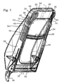
- the backrest frame shown in the figures represents the supporting structure a backrest of a motor vehicle seat.
- the backrest frame is made from a sheet metal blank by a plastic molding process. The result is called a pressed sheet metal part.
- This sheet metal pressed part has a main area 20 and an edge.
- the edge runs around a U-shape. It is made in one piece from a top rim 22, a left curved corner edge 24, a right curved Corner edge 26, a left side edge 28 and a right side edge 30.
- Two large cutouts 32 are provided in the main area, namely one upper cutout 32 and a lower cutout 34. They are by one transverse web 36 separated, this web is profiled.
- the pressed sheet metal is essentially mirror-symmetrical to a central plane 37.
- Two beads are arranged in the upper area of the pressed sheet metal part is discussed in more detail below. It is a left stiffening Bead 38 and an identical, right bead 40. The following is the left bead 38 described, the same applies to the right bead 40.
- the bead 38 is located on the one hand in the side edge 28, namely in an upper one End area 42 of this side edge 28 and on the other hand in the main area 20.
- the upper end region 42 is a shorter piece of the entire side edge 28, it extends about 1 / 8th of the total length of the page margin 28. It begins a little below the transition from the left margin 28 in the left corner edge 24, in particular in FIG. 1, is the distance, which is a few millimeters.
- the main area 20 is thus located directly on the upper area End area adjacent portion of the main area a first main area part the bead.
- a second main part of the bead is located immediately following this first part of the main area and in Neighborhood of the associated corner edge, i.e. the left corner edge 24.
- This second main area part has no contact with the edge, but is only in the main area. It is from the neighboring one Corner edge 24 by an undisturbed, arcuate strip 46 of the Main area 20 separately.
- the edges of the bead 38 follow on the one hand the curvature of the corner edge and on the other hand the curvature of the upper Detail 32.
- the bead 38 to the plane of symmetry Backrest frame completed by a parallel to this Course.
- the bead 28 has essentially boundary lines, which are either parallel to the plane of symmetry or essentially run across this.
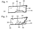
- the bead has a bead edge 48 which is offset parallel to one Edge between the side edge 28 and the main area 20. It still has a first bead surface 50 in the region of the upper end region, this first bead surface 50 is located in a plane that is offset in parallel to the level of the left side edge 28. It also has a second bead surface 52, which is in a plane that is offset parallel to Level of the main area around the bead 38. This second bead surface 52 consists of the two above Main area parts together. The bead jumps about 15 mm over the undisturbed material. More specifically the first bead surface is at a distance of about 15 mm beyond the left side edge 28.
- the second bead surface 52 is located at a distance of about 15 mm to the front, in the direction in which the Side edge 28 projects, offset from the undisturbed main area 20.
- Each bead 38, 40 extends across about 20 transverse to the plane of symmetry % of the transverse dimension of the sheet metal part.
- the first bead surface 50 is in the essentially a rectangle.
- the second bead surface 52 has one more complicated form.
- the bead 28 does not extend over the entire height of the side edge 28, rather it ends at a distance from the free end of the page edge. It stretches more than half, especially between 60 and 80% of the height of the page margin 28. At the free end, the page margin is after bent outside in a U-shape. There is a sidebar there.
- Left and right side beads 54 are also provided in each case.
- the left side bead 54 which is identical in construction, is again described below is with the right side bead. It is located a short distance below the bead 28, between the two is an undisturbed area 56. This is about 15 to 20 mm high.
- the side bead has one across the top edge 22 Length dimension, which is roughly the corresponding dimension of the left Bead 38 corresponds. It is also the same dimension, i.e. about 15 mm, molded out of the undisturbed sheet material.
- the side bead 54 has in the area of the left side edge 28 a bead surface that is approximately rectangular is in any case in the form of an elongated rectangle. In the main area 20 the side bead 54 is relatively small, it extends here for about 20 to 30 mm, this corresponds approximately to the width of the bead 28 in its lowest section.
- the side bead 54 closes at the bottom approximately with the lower edge of the web 36 from.
- the side bead 54 is located in the area of the upper half of the side edge 28. Your bead edge extends the bead edge 48.
- both side edges 28, 30 are elongated support plates applied to the inner surface of the side edge 28 or 30. You limit along with this inner surface elongated pockets. In these pockets are upper arms 58 of backrest joints, which are known per se are inserted and fixed. This enables simple plug-in assembly the already finished, also padded backrest.
Landscapes
- Engineering & Computer Science (AREA)
- Aviation & Aerospace Engineering (AREA)
- Transportation (AREA)
- Mechanical Engineering (AREA)
- Seats For Vehicles (AREA)
- Chair Legs, Seat Parts, And Backrests (AREA)
Abstract
Description
- Fig. 1:
- eine perspektivische Darstellung eines Rückenlehnenrahmens nach der Erfindung,
- Fig. 2:
- einen Schnitt des Rückenlehnenrahmens entlang der Schnittlinie II - II in Figur 3
- Fig. 3:
- eine Draufsicht auf den Rückenlehnenrahmen,
- Fig. 4:
- ein Schnitt entlang der Schnittlinie IV-IV in Fig. 3 und
- Fig. 5:
- ein Schnitt entlang der Schnittlinie V-V in Fig. 3.
Claims (12)
- Rückenlehne eines Kraftfahrzeugsitzes, mit einem Rückenlehnenrahmen, der aus einem Blechzuschnitt zu einem Blechpressteil geformt ist und einen Hauptbereich (20) sowie einen quer zu diesem Hauptbereich (20) verlaufenden Rand aufweist, welcher Rand aus ineinander übergehenden Teilstücken zusammengesetzt ist, nämlich aus einem Toprand (22), einem linken und einem rechten gekrümmten Eckrand (24, 26) und einem linken und einem rechten Seitenrand (30), wobei eine linke und eine rechte, versteifende Sicke (38, 40) vorgesehen ist, die sich jeweils in einem oberen Endbereich (42) des Seitenrandes (28, 30) und im Hauptbereich (20) a) im unmittelbar an diesen oberen Endbereich (42) angrenzenden Teilstück des Hauptbereichs (20) und b) in der Nachbarschaft des zugehörigen Eckrandes (24, 26) befindet.
- Rückenlehne nach Anspruch 1, dadurch gekennzeichnet, dass die Sicke (38, 40) zwischen dem oberen Endbereich (42) des jeweiligen Seitenrandes (28, 30) und dem unmittelbar benachbarten Teilstück des Hauptbereichs (20) eine Sickenkante (48) ausbildet, die versetzt verläuft gegenüber einer Kante zwischen Hauptbereich (20) und Seitenrand unterhalb des oberen Endbereichs (42) des Seitenrandes (28, 30).
- Rückenlehne nach Anspruch 1, dadurch gekennzeichnet, dass in der Sicke (38, 40) das Blechpressteil so verformt ist, dass es im Hauptbereich (20) in der Richtung versetzt ist, in der auch der Rand vorspringt und dass es im Bereich des Seitenrandes (28, 30) nach innen hin versetzt ist.
- Rückenlehne nach Anspruch 1, dadurch gekennzeichnet, dass sich zwischen Eckrand und Sicke (38, 40) ein ungestörter, bogenförmiger Streifen (46) des Hauptbereichs (20) befindet.
- Rückenlehne nach Anspruch 1, dadurch gekennzeichnet, dass der Blechzuschnitt in der Sicke (38, 40) um 3 bis 30 mm, vorzugsweise um fünfzehn Millimeter gegenüber dem ungestörten Blechzuschnitt sowie dem ungestörten Rand versetzt verläuft.
- Rückenlehne nach Anspruch 1, dadurch gekennzeichnet, dass die Sicke (38, 40) in einer Richtung quer zum Toprand (22), also von oben nach unten eine Längsausdehnung hat, die etwa doppelt so groß ist wie die Länge des oberen Endbereichs (42) des Seitenrandes (28, 30).
- Rückenlehne nach Anspruch 1, dadurch gekennzeichnet, dass der Rand ein freies Randende hat und dass dieses freie Randende sich außerhalb der Sicke (38, 40) befindet.
- Rückenlehne nach Anspruch 1, dadurch gekennzeichnet, dass die Sicke (38, 40) an den Eckrand (24, 26) angrenzt, sich aber nicht in den Eckrand (24, 26) erstreckt.
- Rückenlehne nach Anspruch 1, dadurch gekennzeichnet, dass jeweils links und rechts unterhalb der Sicke (38, 40) eine Seitensicke (54) vorgesehen ist, die sich im Abstand von der Sicke (38, 40) befindet und die im Seitenrand (28, 30) und in einem angrenzenden Teilstück des Hauptbereichs (20) ausgebildet ist.
- Rückenlehne nach Anspruch 1, dadurch gekennzeichnet, dass der Rand an seinem freien Ende unter Bildung einer Randleiste nach aussen zurückgebogen ist.
- Rückenlehne nach Anspruch 10, dadurch gekennzeichnet, dass der Rand ein freies Randende hat und dass sich dieses freie Randende außerhalb der Seitensicke (54) befindet.
- Rückenlehne nach Anspruch 9, dadurch gekennzeichnet, dass sich die Seitensicke (54) im Bereich der oberen Hälfte des Seitenrandes (28, 30) befindet.
Applications Claiming Priority (2)
| Application Number | Priority Date | Filing Date | Title |
|---|---|---|---|
| DE10042850 | 2000-08-30 | ||
| DE10042850A DE10042850A1 (de) | 2000-08-30 | 2000-08-30 | Rückenlehne eines Kraftfahrzeugsitzes mit einem Rückenlehnenrahmen als Blechpressteil |
Publications (3)
| Publication Number | Publication Date |
|---|---|
| EP1190894A2 true EP1190894A2 (de) | 2002-03-27 |
| EP1190894A3 EP1190894A3 (de) | 2003-11-12 |
| EP1190894B1 EP1190894B1 (de) | 2005-08-17 |
Family
ID=7654471
Family Applications (1)
| Application Number | Title | Priority Date | Filing Date |
|---|---|---|---|
| EP01109315A Expired - Lifetime EP1190894B1 (de) | 2000-08-30 | 2001-04-11 | Rückenlehne eines Kraftfahrzeugsitzes mit einem Rückenlehnenrahmen als Blechpressteil |
Country Status (3)
| Country | Link |
|---|---|
| US (1) | US6607247B2 (de) |
| EP (1) | EP1190894B1 (de) |
| DE (2) | DE10042850A1 (de) |
Cited By (1)
| Publication number | Priority date | Publication date | Assignee | Title |
|---|---|---|---|---|
| EP1674335A1 (de) | 2004-12-24 | 2006-06-28 | Renault s.a.s. | Kraftfahrzeugsitz mit Schalenrückenlehne |
Families Citing this family (16)
| Publication number | Priority date | Publication date | Assignee | Title |
|---|---|---|---|---|
| WO2007048256A1 (en) * | 2005-10-25 | 2007-05-03 | Intier Automotive Inc. | Energy absorbing seat frame |
| DE102008036646A1 (de) | 2007-10-26 | 2009-04-30 | C. Rob. Hammerstein Gmbh & Co. Kg | Rahmenseitenteil eines Fahrzeugsitzes |
| JP5719774B2 (ja) * | 2008-10-16 | 2015-05-20 | ジョンソン コントロールズ テクノロジー カンパニーJohnson Controls Technology Company | 一部品座席構造及び座席構造を作成するための冷間成形工程 |
| CN102317643B (zh) | 2009-02-19 | 2014-10-29 | 玛格纳斯太尔汽车技术股份公司 | 具有振动阻尼的平面部件 |
| WO2011014506A1 (en) | 2009-07-27 | 2011-02-03 | Johnson Controls Technology Company | One-piece seat structures and method of forming |
| EP2536588B8 (de) * | 2010-02-19 | 2018-05-02 | Adient Luxembourg Holding S.à r.l. | Einstückige rückenlehnenstruktur und herstellungsverfahren |
| US8439566B2 (en) * | 2010-03-09 | 2013-05-14 | Caterpillar Global Mining Equipment Llc | Wear pad adjustment assembly |
| DE102010040593A1 (de) | 2010-09-10 | 2012-03-15 | Johnson Controls Gmbh | Verfahren zur Herstellung eines Rückenlehnenrahmenelements |
| US9010855B2 (en) * | 2010-09-17 | 2015-04-21 | Honda Motor Co., Ltd. | Vehicle seat |
| JP2014502581A (ja) * | 2010-12-21 | 2014-02-03 | ジョンソン コントロールズ テクノロジー カンパニー | 統合されたバックパネルを有する一体バックフレーム |
| WO2013008752A1 (ja) * | 2011-07-13 | 2013-01-17 | 東レ株式会社 | 背もたれ用フレーム構造体およびその製造方法 |
| CN103648334B (zh) * | 2011-07-15 | 2016-01-20 | 东丽株式会社 | 靠背用框架结构体及其制造方法 |
| JP2015504819A (ja) * | 2012-01-26 | 2015-02-16 | ジョンソン コントロールズ テクノロジー カンパニーJohnson Controls Technology Company | ワンピース型背もたれ構造体の製造方法 |
| USD697726S1 (en) | 2012-09-20 | 2014-01-21 | Steelcase Inc. | Chair |
| CN105073491A (zh) * | 2013-02-18 | 2015-11-18 | 佛吉亚汽车座椅有限责任公司 | 用于车辆座椅的座椅背部 |
| WO2018060825A1 (en) * | 2016-09-27 | 2018-04-05 | Proma Spa | Seat for vehicles having an engagement edge |
Family Cites Families (22)
| Publication number | Priority date | Publication date | Assignee | Title |
|---|---|---|---|---|
| JPS49575B1 (de) * | 1967-08-26 | 1974-01-08 | ||
| DE3239292A1 (de) * | 1981-11-11 | 1983-05-19 | Keiper Automobiltechnik Gmbh & Co Kg, 5630 Remscheid | Rueckenlehnenrahmen fuer sitze, insbesondere fuer kraftfahrzeugsitze |
| FR2594760B1 (fr) * | 1986-02-21 | 1989-11-10 | Renault | Armature de siege a modules de construction assembles |
| DE3936418C1 (de) * | 1989-11-02 | 1990-10-31 | Keiper Recaro Gmbh & Co, 5630 Remscheid, De | |
| DE4238549C2 (de) * | 1992-11-14 | 1997-06-12 | Daimler Benz Ag | Kraftfahrzeugsitz |
| DE4402864C2 (de) * | 1994-01-31 | 1997-08-21 | Keiper Recaro Gmbh Co | Rückenlehnenpolster für Rücksitze von Kraftfahrzeugen |
| DE4419139C2 (de) * | 1994-05-30 | 1997-08-21 | Euromotive Gmbh | Rahmenkonstruktion für den Sitz eines Fahrzeuges |
| SE9402877L (sv) * | 1994-08-30 | 1996-05-15 | Autosafe Automobile I Stockhol | Anordning för att motverka pisksnärtskador |
| DE19613164C2 (de) * | 1996-04-02 | 1998-06-10 | Keiper Recaro Gmbh Co | Rückenlehne für Fahrzeugsitze |
| JP3358450B2 (ja) * | 1996-07-09 | 2002-12-16 | 三菱自動車工業株式会社 | 自動車用座席 |
| WO1998008705A1 (en) * | 1996-08-29 | 1998-03-05 | Lear Corporation | Vehicle seat assembly |
| US5735572A (en) * | 1997-01-16 | 1998-04-07 | Ford Global Technologies, Inc. | Vehicle seat back frame and airbag module assembly |
| US6059369A (en) * | 1997-05-01 | 2000-05-09 | Lear Corporation | Composite vehicle seat back frame and method of manufacturing thereof |
| US5749135A (en) * | 1997-03-19 | 1998-05-12 | General Motors Corporation | Method for extruding integral seat back frame |
| US5836647A (en) * | 1997-05-20 | 1998-11-17 | Turman; Ben | Vehicle seat with shock absorption |
| US5882458A (en) * | 1997-07-24 | 1999-03-16 | Bartell Machinery Systems,Llc | Tire bead forming method and apparatus |
| DE19746234A1 (de) * | 1997-10-20 | 1999-04-22 | Volkswagen Ag | Fahrzeugsitz |
| JPH11129854A (ja) * | 1997-10-30 | 1999-05-18 | Ts Tec Kk | サイドエアーバッグ装置を備える車輌用シート |
| US6074004A (en) * | 1998-02-19 | 2000-06-13 | Carmichael; Donald Edwin | Seat back frame for absorbing energy |
| JP3406530B2 (ja) * | 1999-01-11 | 2003-05-12 | 株式会社タチエス | 車両用ヒンジ付きシートのシートバック構造 |
| AT3804U1 (de) * | 1999-05-27 | 2000-08-25 | Tcg Unitech Ag | Sitzlehne für ein kraftfahrzeug |
| DE19927403C2 (de) * | 1999-06-16 | 2003-02-13 | Daimler Chrysler Ag | Rückenlehne für einen Fahrzeugsitz |
-
2000
- 2000-08-30 DE DE10042850A patent/DE10042850A1/de not_active Withdrawn
-
2001
- 2001-04-11 DE DE50107103T patent/DE50107103D1/de not_active Expired - Fee Related
- 2001-04-11 EP EP01109315A patent/EP1190894B1/de not_active Expired - Lifetime
- 2001-07-11 US US09/903,043 patent/US6607247B2/en not_active Expired - Fee Related
Non-Patent Citations (1)
| Title |
|---|
| None |
Cited By (1)
| Publication number | Priority date | Publication date | Assignee | Title |
|---|---|---|---|---|
| EP1674335A1 (de) | 2004-12-24 | 2006-06-28 | Renault s.a.s. | Kraftfahrzeugsitz mit Schalenrückenlehne |
Also Published As
| Publication number | Publication date |
|---|---|
| DE50107103D1 (de) | 2005-09-22 |
| US6607247B2 (en) | 2003-08-19 |
| EP1190894A3 (de) | 2003-11-12 |
| EP1190894B1 (de) | 2005-08-17 |
| US20020024248A1 (en) | 2002-02-28 |
| DE10042850A1 (de) | 2002-03-14 |
Similar Documents
| Publication | Publication Date | Title |
|---|---|---|
| DE69412350T2 (de) | Rahmen für Sitzrückenlehne | |
| DE19802873B4 (de) | Rückenlehnenrahmen | |
| EP1190894B1 (de) | Rückenlehne eines Kraftfahrzeugsitzes mit einem Rückenlehnenrahmen als Blechpressteil | |
| DE3872650T2 (de) | Einstellbare rueckensitzlehne fuer kraftfahrzeuge. | |
| EP1080986B1 (de) | Sitztiefeneinstellvorrichtung für einen Fahrzeugsitz | |
| DE69704044T2 (de) | Fahrzeugsitzschiene und mit einer solchen Sitzschiene ausgerüsteter Sitz | |
| DE2707885C2 (de) | Energieabsorbierende Stoßstange für Fahrzeuge, insbesondere Kraftfahrzeuge | |
| DE4402864C2 (de) | Rückenlehnenpolster für Rücksitze von Kraftfahrzeugen | |
| DE19825225A1 (de) | Wölbungsverstellbare Stütze, insbesondere Lordosenstütze, für Sitze und Liegen aller Art | |
| DE102008053471A1 (de) | Fahrzeugsitz | |
| DE4138647A1 (de) | Ruecklehnenrahmen eines sitzes | |
| DE102008051072A1 (de) | Kraftfahrzeugsitz mit Lendenstütze für ein Anti-Schleudertraumasystem | |
| DE69920189T2 (de) | Rahmen für fahrzeugsitze | |
| DE19905215A1 (de) | Sitz | |
| DE2940463A1 (de) | In sitzlaengsrichtung verstellbarer automobilsitz | |
| EP0096859A2 (de) | Rückenlehne für Fahrzeugsitze | |
| EP0926970B1 (de) | Federbrücke für eine untermatratze | |
| DE69619779T2 (de) | Sitzgleitschiene | |
| DE2053665C3 (de) | Höhen- und neigungsverstellbarer Fahrzeugsitz, insbesondere für Kraftfahrzeuge | |
| DE102023200413B4 (de) | Sitzschiene für fahrzeug | |
| DE69112722T3 (de) | Versteifung für ein Windschutzscheiben-Wischblatt. | |
| DE3301309A1 (de) | Verstellvorrichtung fuer fahrzeug-sitze | |
| DE19543404B4 (de) | Mitteltunnel für die Bodengruppe eines Kraftfahrzeuges | |
| DE10309636B4 (de) | Karosserieträger mit einer den Verformungsverlauf bei einem Aufprall beeinflussenden Nebenform | |
| DE19942973B4 (de) | Fahrzeugsitz mit Crashenergieabsorption |
Legal Events
| Date | Code | Title | Description |
|---|---|---|---|
| PUAI | Public reference made under article 153(3) epc to a published international application that has entered the european phase |
Free format text: ORIGINAL CODE: 0009012 |
|
| AK | Designated contracting states |
Kind code of ref document: A2 Designated state(s): AT BE CH CY DE DK ES FI FR GB GR IE IT LI LU MC NL PT SE TR |
|
| AX | Request for extension of the european patent |
Free format text: AL;LT;LV;MK;RO;SI |
|
| RIN1 | Information on inventor provided before grant (corrected) |
Inventor name: STRENGER, MARTIN Inventor name: HOUSTON, ROBERT Inventor name: BECKER, BURCKHARD |
|
| PUAL | Search report despatched |
Free format text: ORIGINAL CODE: 0009013 |
|
| AK | Designated contracting states |
Kind code of ref document: A3 Designated state(s): AT BE CH CY DE DK ES FI FR GB GR IE IT LI LU MC NL PT SE TR |
|
| AX | Request for extension of the european patent |
Extension state: AL LT LV MK RO SI |
|
| RIC1 | Information provided on ipc code assigned before grant |
Ipc: 7B 60N 2/64 A Ipc: 7B 60N 2/68 B |
|
| 17P | Request for examination filed |
Effective date: 20040512 |
|
| AKX | Designation fees paid |
Designated state(s): DE FR GB |
|
| GRAP | Despatch of communication of intention to grant a patent |
Free format text: ORIGINAL CODE: EPIDOSNIGR1 |
|
| GRAS | Grant fee paid |
Free format text: ORIGINAL CODE: EPIDOSNIGR3 |
|
| GRAA | (expected) grant |
Free format text: ORIGINAL CODE: 0009210 |
|
| AK | Designated contracting states |
Kind code of ref document: B1 Designated state(s): DE FR GB |
|
| PG25 | Lapsed in a contracting state [announced via postgrant information from national office to epo] |
Ref country code: GB Free format text: LAPSE BECAUSE OF FAILURE TO SUBMIT A TRANSLATION OF THE DESCRIPTION OR TO PAY THE FEE WITHIN THE PRESCRIBED TIME-LIMIT Effective date: 20050817 |
|
| REG | Reference to a national code |
Ref country code: GB Ref legal event code: FG4D Free format text: NOT ENGLISH |
|
| REF | Corresponds to: |
Ref document number: 50107103 Country of ref document: DE Date of ref document: 20050922 Kind code of ref document: P |
|
| GBV | Gb: ep patent (uk) treated as always having been void in accordance with gb section 77(7)/1977 [no translation filed] |
Effective date: 20050817 |
|
| ET | Fr: translation filed | ||
| PLBE | No opposition filed within time limit |
Free format text: ORIGINAL CODE: 0009261 |
|
| STAA | Information on the status of an ep patent application or granted ep patent |
Free format text: STATUS: NO OPPOSITION FILED WITHIN TIME LIMIT |
|
| 26N | No opposition filed |
Effective date: 20060518 |
|
| PGFP | Annual fee paid to national office [announced via postgrant information from national office to epo] |
Ref country code: DE Payment date: 20080218 Year of fee payment: 8 Ref country code: FR Payment date: 20080218 Year of fee payment: 8 |
|
| REG | Reference to a national code |
Ref country code: FR Ref legal event code: ST Effective date: 20091231 |
|
| PG25 | Lapsed in a contracting state [announced via postgrant information from national office to epo] |
Ref country code: DE Free format text: LAPSE BECAUSE OF NON-PAYMENT OF DUE FEES Effective date: 20091103 |
|
| PG25 | Lapsed in a contracting state [announced via postgrant information from national office to epo] |
Ref country code: FR Free format text: LAPSE BECAUSE OF NON-PAYMENT OF DUE FEES Effective date: 20091222 |