EP1190973A2 - Klebebandabroller - Google Patents
Klebebandabroller Download PDFInfo
- Publication number
- EP1190973A2 EP1190973A2 EP01117081A EP01117081A EP1190973A2 EP 1190973 A2 EP1190973 A2 EP 1190973A2 EP 01117081 A EP01117081 A EP 01117081A EP 01117081 A EP01117081 A EP 01117081A EP 1190973 A2 EP1190973 A2 EP 1190973A2
- Authority
- EP
- European Patent Office
- Prior art keywords
- adhesive tape
- housing
- dispenser according
- cutting blade
- tape dispenser
- Prior art date
- Legal status (The legal status is an assumption and is not a legal conclusion. Google has not performed a legal analysis and makes no representation as to the accuracy of the status listed.)
- Granted
Links
Images


Classifications
-
- B—PERFORMING OPERATIONS; TRANSPORTING
- B65—CONVEYING; PACKING; STORING; HANDLING THIN OR FILAMENTARY MATERIAL
- B65H—HANDLING THIN OR FILAMENTARY MATERIAL, e.g. SHEETS, WEBS, CABLES
- B65H35/00—Delivering articles from cutting or line-perforating machines; Article or web delivery apparatus incorporating cutting or line-perforating devices, e.g. adhesive tape dispensers
- B65H35/0006—Article or web delivery apparatus incorporating cutting or line-perforating devices
- B65H35/0073—Details
- B65H35/008—Arrangements or adaptations of cutting devices
- B65H35/0086—Arrangements or adaptations of cutting devices using movable cutting elements
-
- B—PERFORMING OPERATIONS; TRANSPORTING
- B65—CONVEYING; PACKING; STORING; HANDLING THIN OR FILAMENTARY MATERIAL
- B65H—HANDLING THIN OR FILAMENTARY MATERIAL, e.g. SHEETS, WEBS, CABLES
- B65H35/00—Delivering articles from cutting or line-perforating machines; Article or web delivery apparatus incorporating cutting or line-perforating devices, e.g. adhesive tape dispensers
- B65H35/0006—Article or web delivery apparatus incorporating cutting or line-perforating devices
- B65H35/002—Hand-held or table apparatus
- B65H35/0026—Hand-held or table apparatus for delivering pressure-sensitive adhesive tape
-
- B—PERFORMING OPERATIONS; TRANSPORTING
- B65—CONVEYING; PACKING; STORING; HANDLING THIN OR FILAMENTARY MATERIAL
- B65H—HANDLING THIN OR FILAMENTARY MATERIAL, e.g. SHEETS, WEBS, CABLES
- B65H37/00—Article or web delivery apparatus incorporating devices for performing specified auxiliary operations
- B65H37/002—Web delivery apparatus, the web serving as support for articles, material or another web
- B65H37/005—Hand-held apparatus
-
- B—PERFORMING OPERATIONS; TRANSPORTING
- B65—CONVEYING; PACKING; STORING; HANDLING THIN OR FILAMENTARY MATERIAL
- B65H—HANDLING THIN OR FILAMENTARY MATERIAL, e.g. SHEETS, WEBS, CABLES
- B65H2402/00—Constructional details of the handling apparatus
- B65H2402/40—Details of frames, housings or mountings of the whole handling apparatus
- B65H2402/44—Housings
- B65H2402/441—Housings movable for facilitating access to area inside the housing, e.g. pivoting or sliding
-
- B—PERFORMING OPERATIONS; TRANSPORTING
- B65—CONVEYING; PACKING; STORING; HANDLING THIN OR FILAMENTARY MATERIAL
- B65H—HANDLING THIN OR FILAMENTARY MATERIAL, e.g. SHEETS, WEBS, CABLES
- B65H2402/00—Constructional details of the handling apparatus
- B65H2402/50—Machine elements
- B65H2402/54—Springs, e.g. helical or leaf springs
-
- B—PERFORMING OPERATIONS; TRANSPORTING
- B65—CONVEYING; PACKING; STORING; HANDLING THIN OR FILAMENTARY MATERIAL
- B65H—HANDLING THIN OR FILAMENTARY MATERIAL, e.g. SHEETS, WEBS, CABLES
- B65H2407/00—Means not provided for in groups B65H2220/00 – B65H2406/00 specially adapted for particular purposes
- B65H2407/10—Safety means, e.g. for preventing injuries or illegal operations
-
- B—PERFORMING OPERATIONS; TRANSPORTING
- B65—CONVEYING; PACKING; STORING; HANDLING THIN OR FILAMENTARY MATERIAL
- B65H—HANDLING THIN OR FILAMENTARY MATERIAL, e.g. SHEETS, WEBS, CABLES
- B65H2701/00—Handled material; Storage means
- B65H2701/30—Handled filamentary material
- B65H2701/37—Tapes
- B65H2701/377—Adhesive tape
Definitions
- the invention relates to an adhesive tape dispenser with a in a housing Arranged receptacle for a roll of tape, with a distance of the receptacle arranged on one side by a deflecting element limited exit gap for the tape to be unrolled and with a on the side of the deflecting element at a lateral distance from the outlet gap arranged cutting blade for cutting off a protruding piece of tape.
- Adhesive tape dispensers of this type are known in which the deflecting element is designed as a deflection roller delimiting the exit gap and at which the cutting blade is rigidly attached to the housing and with their Cut over this protrudes. The distance between the exit gap and the cutting blade ensures that a sufficient piece of the Adhesive tape protrudes from the housing, so that the tape is not can slide back into the housing.
- the known tape dispensers of this type it is felt to be disadvantageous that the intended Use the risk of injury to the fixed cutting blade consists.
- the cutting blade has therefore already been proposed to be arranged pivotably on the housing of the tape dispenser. The panning of the knife in relation to the housing takes place there independently from the tape by hand. Operating errors that lead to injuries can therefore not be excluded.
- the object of the invention is an adhesive tape dispenser to develop the type specified at the beginning, which without a Risk of injury is easy to handle.
- the solution according to the invention is primarily based on the idea that the deflection element when cutting off the protruding piece of adhesive tape is movable against the force of a spring in the direction of the cutting blade and that the cutting blade is in operative connection with the deflecting element and under its influence between a retracted end position and a with its cutting edge movable beyond the end position projecting beyond the housing is.
- the measures according to the invention thus ensure that the cutting blade only then automatically from its protected position is moved out when a protruding piece of adhesive tape is cut off becomes. Incorrect operations that could lead to injuries are therefore largely excluded.
- a preferred embodiment of the invention provides that the cutting blade is arranged in a slide guide of the housing.
- a first variant of the invention provides that the deflecting element at the free end of a Housing spring-loaded lever is arranged, the Lever can be articulated to the cutting blade via a coupling member.
- the deflecting element arranged at the free end of a spring tongue clamped to the housing is, the spring tongue expediently via a resilient coupling member can be coupled to the cutting blade.
- a resilient coupling member designed as a spiral spring, which at one end in the thrust guide engages where it carries the cutting blade and with its other End at a distance from the deflecting element and expediently from the Clamping point is connected to the spring tongue.
- the cutting blade only needs a defined displacement to its To have an effect, it is advantageous if the path of movement of the deflecting element is limited by a housing stop.
- the spring tongue and the resilient coupling member preferably as a one-piece molded part Plastic are formed.
- the cutting blade can be in the range of free end of the resilient coupling member can be embedded in the molded part.
- the housing consists of two housing shells, one around the roll axis of the adhesive tape parallel pivot axis pivotable against each other are and which are releasably locked together in their closed position.
- the Both housing shells form appropriately on their swivel axis End a common footprint and limit at their other ends together upward with respect to the footprint Pointing exit gap with the cutting blade on one of the housing shells arranged obliquely above the outlet gap with respect to the footprint is.
- the cutting edge of the cutting blade is through one to the exit gap parallel slot opening of the relevant housing shell slidable.
- An advantageous embodiment of the invention provides that the spring tongue mounted on the housing shell on the cutting blade side its front end, which carries the deflection element, into an open edge The outlet channel of the other housing shell engages to limit the gap.
- the receptacle for the roll of adhesive tape is on one of the Housing shells rotatably fixable thru axle, which is practical on the retaining tongues projecting beyond the housing shell is attachable.
- the thru-axle advantageously engages with its non-circular Form-fitting ends in a correspondingly non-circular opening between the two housing shells.
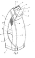
- the tape dispenser shown in the drawing has one of two housing shells 10, 12 composite housing in which a Thru axle 14 is arranged for receiving an adhesive tape roll 16.
- the upper area of the housing has a deflection element 18 limited exit gap 20 for the tape 22 to be unrolled and a arranged on the side of the deflecting element 18 at a distance from the outlet gap 20 Cutting blade 24 for cutting off a protruding piece of adhesive tape 62 on.
- the two housing shells 10, 12 form at their lower End of a footprint formed by a latched base part 26 and are about a pivot axis parallel to the unwind axis of the adhesive tape roll 16 28 to open the housing pivotable against each other and in their 1 and 2 shown locking position with each other via locking elements 30 latched.
- the latching connection 30 can press against one another by spring elastic arranged on the side walls 32 of the housing shell 12 corrugated grip areas 34 are solved. As shown in Figs. 1 and 3 can be seen the outlet gap 20 for the adhesive tape 22 obliquely upwards.
- the cutting blade 24 shown in the Embodiment has a serrated edge 38 is located in a slot opening 40 of the housing shell parallel to the outlet gap 20 10th
- the thru axle 14 for receiving the adhesive tape roll 16 is on the housing shell 12 transversely projecting retaining tongues 42 can be attached in a rotationally fixed manner. With its non-circular ends 44, it positively engages between the two housing shells 10, 12 formed a gusset-like opening 46.
- a gusset-like opening 46 Around also take up rolls of adhesive tape with a smaller inner roll diameter can, are on the mutually facing inner surfaces of the retaining tongues cylindrical retaining rings 70 are formed on which the tape roll with its open ends can be plugged.
- the retaining tabs 42 are for this purpose resiliently spreadable against each other.
- the deflection element 18 through the thickened free end one with its other end 47 at clamping points 48 of the housing shell 10 clamped spring tongue 50 is formed.
- the spring tongue 50 formed as a spiral spring resilient coupling member 52, the with its end 54 carrying the cutting blade 24 in the outer wall 58 the housing shell 10 is supported and in the direction of arrow 60 according to Art a slide guide is guided. If so when rolling and subsequent Cutting the adhesive tape 22 off the tape end to be cut 62 in Pulled in the direction of arrow 64, the deflection element 18 is expanded of the exit gap 20 up to the stop 66 against the spring force the spring tongue 50 and the resilient coupling member 52 taken.
- the invention relates to an adhesive tape dispenser with one arranged in a housing 10, 12 Receptacle 14 for an adhesive tape roll 16. At a distance from the receptacle 14 there is an outlet gap 20 on the housing 10, 12 for the adhesive tape to be unrolled arranged, which is delimited on one side by a deflection element 18. Further is located at a distance from the outlet gap 20 on the side of the deflecting element 18 a cutting blade 24 for cutting off a protruding piece of adhesive tape 62. Easy handling without risk of injury thereby enabling the deflecting element 18 when the protruding part is separated Adhesive tape piece 62 against the force of a spring 50 in the direction Cutting blade 24 is movable. The cutting blade 24 is in Active connection with the deflecting element 18 and is under its influence between a retracted end position and one with its cutting edge 38 movable beyond the end position protruding.
Landscapes
- Adhesive Tape Dispensing Devices (AREA)
Abstract
Description
- Fig. 1
- einen Klebebandabroller in schaubildlicher Darstellung;
- Fig. 2
- den Klebebandabroller nach Fig. 1 in schaubildlicher Explosivdarstellung;
- Fig. 3
- einen senkrechten Schnitt durch den Klebebandabroller nach Fig. 1.
Claims (20)
- Klebebandabroller mit einer in einem Gehäuse (10, 12) angeordneten Aufnahme (14) für eine Klebebandrolle (16), mit einem im Abstand von der Aufnahme (14) am Gehäuse angeordneten, einseitig durch ein Umlenkelement (18) begrenzten Austrittsspalt (20) für das abzurollende Klebeband (22) und mit einer auf der Seite des Umlenkelements im Abstand vom Austrittsspalt (20) angeordneten Schneidklinge (24) zum Abtrennen eines überstehenden Klebebandstücks (62), dadurch gekennzeichnet, daß das Umlenkelement (18) beim Abtrennen des überstehenden Klebebandstücks (62) entgegen der Kraft einer Feder (50, 52) in Richtung Schneidklinge (24) bewegbar ist, und daß die Schneidklinge (24) in Wirkverbindung mit dem Umlenkelement (18) steht und unter dessen Einwirkung zwischen einer eingezogenen Endstellung und einer mit ihrer Schneide (38) über das Gehäuse überstehenden Endstellung bewegbar ist.
- Klebebandabroller nach Anspruch 1, dadurch gekennzeichnet, daß die Schneidklinge (24) in einer Schubführung (56) des Gehäuses (10) angeordnet ist.
- Klebebandabroller nach Anspruch 1 oder 2, dadurch gekennzeichnet, daß das Umlenkelement (18) am freien Ende eines am Gehäuse gelagerten federunterstützten Hebels (50) angeordnet ist.
- Klebebandabroller nach Anspruch 3, dadurch gekennzeichnet, daß der Hebel (50) über ein Koppelglied (52) an die Schneidklinge (54) angelenkt ist.
- Klebebandabroller nach einem der Ansprüche 1 bis 4, dadurch gekennzeichnet, daß das Umlenkelement (18) am freien Ende einer am Gehäuse (10) eingespannten Federzunge (50) angeordnet ist.
- Klebebandabroller nach Anspruch 5, dadurch gekennzeichnet, daß die Federzunge (50) über ein federndes Koppelglied (52) mit der Schneidklinge (24) gekoppelt ist.
- Klebebandabroller nach Anspruch 6, dadurch gekennzeichnet, daß das federnde Koppelglied (52) als Biegefeder ausgebildet ist, die an ihrem einen Ende in die Schubführung (54) eingreift und die Schneidklinge (24) trägt und mit ihrem andere Ende im Abstand vom Umlenkelement (18) und von der Einspannstelle (48) mit der Federzunge (50) verbunden ist.
- Klebebandabroller nach einem der Ansprüche 1 bis 7, gekennzeichnet durch einen gehäusefesten Anschlag (66) für das Umlenkelement (18).
- Klebebandabroller nach einem der Ansprüche 5 bis 8, dadurch gekennzeichnet, daß die Federzunge (50) und das federnde Koppelglied (52) als einstückiges Formteil vorzugsweise aus Kunststoff ausgebildet sind.
- Klebebandabroller nach Anspruch 9, dadurch gekennzeichnet, daß die Schneidklinge (24) in das Formteil eingebettet ist.
- Klebebandabroller nach einem der Ansprüche 1 bis 10, dadurch gekennzeichnet, daß das Gehäuse aus zwei Gehäuseschalen (10, 12) besteht, die um eine zur Abrollachse der Klebebandrolle (16) parallele Schwenkachse (28) gegeneinander verschwenkbar sind und die in ihrer Schließstellung lösbar miteinander verrastbar sind.
- Klebebandabroller nach Anspruch 11, dadurch gekennzeichnet, daß die beiden Gehäuseschalen (10, 12) an ihrem einen, schwenkachsenseitigen Ende eine gemeinsame Stellfläche (26) bilden und mit ihrem anderen Ende gemeinsam den bezüglich der Stellfläche (26) schräg nach oben weisenden Austrittsspalt (20) begrenzen.
- Klebebandabroller mit einer in einem Gehäuse (10, 12) angeordneten Aufnahme (14) für eine Klebebandrolle (16), mit einem im Abstand von der Aufnahme (14) am Gehäuse angeordneten, einseitig durch ein Umlenkelement (18) begrenzten Austrittsspalt (20) für das abzurollende Klebeband (22) und mit einer auf der Seite des Umlenkelements im Abstand vom Austrittsspalt (20) angeordneten Schneidklinge (24) zum Abtrennen eines überstehenden Klebebandstücks (62), dadurch gekennzeichnet, daß das Gehäuse aus zwei Gehäuseschalen (10, 12) besteht, die um eine zur Abrollachse der Klebebandrolle (16) parallele Schwenkachse (28) gegeneinander verschwenkbar sind und die in ihrer Schließstellung lösbar miteinander verrastbar sind und daß die beiden Gehäuseschalen (10, 12) an ihrem einen, schwenkachsenseitigen Ende eine gemeinsame Stellfläche (26) bilden und mit ihrem anderen Ende gemeinsam den bezüglich der Stellfläche (26) schräg nach oben weisenden Austrittsspalt (20) begrenzen.
- Klebebandabroller nach Anspruch 12 oder 13, dadurch gekennzeichnet, daß die Schneidklinge (24) an einer der Gehäuseschalen (10) bezüglich der Stellfläche oberhalb des Austrittsspalts (20) angeordnet ist.
- Klebebandabroller nach Anspruch 14, dadurch gekennzeichnet, daß die Schneide (38) der Schneidklinge (24) durch eine zum Austrittsspalt (20) parallele Schlitzöffnung (40) der betreffenden Gehäuseschale (10) hindurch verschiebbar ist.
- Klebebandabroller nach einem der Ansprüche 12 bis 15, dadurch gekennzeichnet, daß die an der schneidklingenseitigen Gehäuseschale (10) gelagerte Federzunge (50) mit ihrem stirnseitigen, das Umlenkelement (18) tragenden Ende in einen randoffenen Austrittskanal (36) der anderen Gehäuseschale (12) spaltbegrenzend eingreift.
- Klebebandabroller nach einem der Ansprüche 11 bis 16, dadurch gekennzeichnet, daß die Aufnahme für die Klebebandrolle (16) als an einer der Gehäuseschalen (12) drehfest fixierbare Steckachse (14) ausgebildet ist.
- Klebebandabroller nach Anspruch 17, dadurch gekennzeichnet, daß die Steckachse (14) auf über die eine Gehäuseschale (12) überstehende Haltezungen (42) drehfest aufsteckbar ist.
- Klebebandabroller nach einem der Ansprüche 17 oder 18, dadurch gekennzeichnet, daß die Steckachse (14) mit ihren unrunden Enden (44) formschlüssig in eine zwischen den beiden Gehäuseschalen gebildete unrunde Öffnung (46) eingreift.
- Klebebandabroller nach einem der Ansprüche 11 bis 19, dadurch gekennzeichnet, daß die Aufnahme für die Klebebandrolle zwei über eine Gehäuseschale (12) überstehende, gegeneinander federnd aufspreizbare Haltezungen (42) aufweist, an deren einander zugewandten Innenseiten je ein zylindrischer Haltering (70) zum Aufstecken der Klebebandrolle angeformt ist.
Applications Claiming Priority (2)
| Application Number | Priority Date | Filing Date | Title |
|---|---|---|---|
| DE10047581 | 2000-09-22 | ||
| DE10047581A DE10047581A1 (de) | 2000-09-22 | 2000-09-22 | Klebebandabroller |
Publications (3)
| Publication Number | Publication Date |
|---|---|
| EP1190973A2 true EP1190973A2 (de) | 2002-03-27 |
| EP1190973A3 EP1190973A3 (de) | 2003-08-13 |
| EP1190973B1 EP1190973B1 (de) | 2005-01-26 |
Family
ID=7657631
Family Applications (1)
| Application Number | Title | Priority Date | Filing Date |
|---|---|---|---|
| EP01117081A Expired - Lifetime EP1190973B1 (de) | 2000-09-22 | 2001-07-13 | Klebebandabroller |
Country Status (2)
| Country | Link |
|---|---|
| EP (1) | EP1190973B1 (de) |
| DE (2) | DE10047581A1 (de) |
Cited By (2)
| Publication number | Priority date | Publication date | Assignee | Title |
|---|---|---|---|---|
| WO2008139209A3 (en) * | 2007-05-16 | 2009-01-15 | Rue De Int Ltd | Document handling apparatus |
| EP1999052A4 (de) * | 2006-03-27 | 2010-11-10 | 3M Innovative Properties Co | Bandspender |
Family Cites Families (10)
| Publication number | Priority date | Publication date | Assignee | Title |
|---|---|---|---|---|
| US2555187A (en) * | 1948-08-21 | 1951-05-29 | Derby Sealers Inc | Tape-dispensing mechanism |
| US2671271A (en) * | 1950-02-11 | 1954-03-09 | Derby Sealers Inc | Measuring and dispensing mechanism for tacky tape |
| GB838038A (en) * | 1957-08-20 | 1960-06-22 | Boeing Co | Improvements in jet engines |
| ES264528Y (es) * | 1982-04-15 | 1983-05-16 | Soporte para cinta autoadhesiva por una o varias caras. | |
| US4586639A (en) * | 1984-07-20 | 1986-05-06 | Clik-Cut, Inc. | Sheet material dispenser and method of dispensing sheet material |
| JPS6392569A (ja) * | 1986-10-02 | 1988-04-23 | Sakae Urushizaki | テ−プカツタ |
| DE3638722A1 (de) * | 1986-11-13 | 1988-05-26 | Pelikan Ag | Geraet zum auftragen eines klebstoff-filmes |
| GB9023809D0 (en) * | 1990-11-02 | 1990-12-12 | Item Products Npd Limited | Tape dispenser |
| NL9400288A (nl) * | 1994-02-25 | 1995-10-02 | Ninaber Peters Krouwel Ind Des | Houder voor plakband of dergelijke. |
| JP2995659B1 (ja) * | 1998-09-18 | 1999-12-27 | 株式会社トンボ鉛筆 | 塗膜転写具 |
-
2000
- 2000-09-22 DE DE10047581A patent/DE10047581A1/de not_active Withdrawn
-
2001
- 2001-07-13 EP EP01117081A patent/EP1190973B1/de not_active Expired - Lifetime
- 2001-07-13 DE DE50105178T patent/DE50105178D1/de not_active Expired - Fee Related
Cited By (3)
| Publication number | Priority date | Publication date | Assignee | Title |
|---|---|---|---|---|
| EP1999052A4 (de) * | 2006-03-27 | 2010-11-10 | 3M Innovative Properties Co | Bandspender |
| US8042592B2 (en) | 2006-03-27 | 2011-10-25 | 3M Innovative Properties Company | Tape dispenser |
| WO2008139209A3 (en) * | 2007-05-16 | 2009-01-15 | Rue De Int Ltd | Document handling apparatus |
Also Published As
| Publication number | Publication date |
|---|---|
| EP1190973B1 (de) | 2005-01-26 |
| DE10047581A1 (de) | 2002-04-11 |
| EP1190973A3 (de) | 2003-08-13 |
| DE50105178D1 (de) | 2005-03-03 |
Similar Documents
| Publication | Publication Date | Title |
|---|---|---|
| DE60210263T2 (de) | Nagelschere | |
| DE3714302A1 (de) | Schere | |
| DE102016008724A1 (de) | Messer | |
| WO1994026180A1 (de) | Chirurgisches instrument mit zwei trennbaren griffbranchen | |
| EP2130609A1 (de) | Austragvorrichtung für Medien | |
| EP1713618B1 (de) | Messerschärfvorrichtung | |
| EP2103558A2 (de) | Klebeband-Handabroller in Kompaktform | |
| EP1190973A2 (de) | Klebebandabroller | |
| EP3476446A1 (de) | Bindung mit sicherungselement für skibremse | |
| EP2789975A1 (de) | Absteckmarker | |
| CH615613A5 (en) | Knife-sharpening unit | |
| DE3335120C2 (de) | Rasierapparat insbesondere als Wegwerfeinheit | |
| DE2940057C2 (de) | Behältnis mit lösbarer Arretierung eines mit einem Handgriff versehenen Werkzeuges | |
| EP1333962A1 (de) | Schneidevorrichtung mit zwei durch handgriffbetätigung aufeinanderzubewegbaren backen | |
| DE2809162A1 (de) | Nassrasierapparat | |
| DE7536240U (de) | Tuerdrueckergarnitur mit rueckholfeder | |
| DE2829439C2 (de) | Staubsauger mit einem Saugschlauch, an dem ein Anschlußstutzen vorgesehen ist | |
| DE9111109U1 (de) | Aufwickelvorrichtung für Binden oder Bandagen | |
| EP1854595A2 (de) | Abschneidevorrichtung mit einem Rastelement zum schrittweisen Bewegen eines Auswuchtgewichtsstrangs | |
| DE9205178U1 (de) | Vielzweckmesser | |
| DE29800977U1 (de) | Vorrichtung zur Aufnahme von Hundekot | |
| DE102014113146B4 (de) | Ballträgerstruktur | |
| AT166271B (de) | Sicherheitsrasierapparat | |
| DE1924651C (de) | Vorrichtung zur hohenverstellbaren Lagerung der Laufrader einer Teppichkehr maschine | |
| DE20100760U1 (de) | Folienspender |
Legal Events
| Date | Code | Title | Description |
|---|---|---|---|
| PUAI | Public reference made under article 153(3) epc to a published international application that has entered the european phase |
Free format text: ORIGINAL CODE: 0009012 |
|
| AK | Designated contracting states |
Kind code of ref document: A2 Designated state(s): AT BE CH CY DE DK ES FI FR GB GR IE IT LI LU MC NL PT SE TR |
|
| AX | Request for extension of the european patent |
Free format text: AL;LT;LV;MK;RO;SI |
|
| PUAL | Search report despatched |
Free format text: ORIGINAL CODE: 0009013 |
|
| AK | Designated contracting states |
Designated state(s): AT BE CH CY DE DK ES FI FR GB GR IE IT LI LU MC NL PT SE TR |
|
| AX | Request for extension of the european patent |
Extension state: AL LT LV MK RO SI |
|
| 17P | Request for examination filed |
Effective date: 20030905 |
|
| AKX | Designation fees paid |
Designated state(s): DE FR GB |
|
| 17Q | First examination report despatched |
Effective date: 20040414 |
|
| GRAP | Despatch of communication of intention to grant a patent |
Free format text: ORIGINAL CODE: EPIDOSNIGR1 |
|
| GRAS | Grant fee paid |
Free format text: ORIGINAL CODE: EPIDOSNIGR3 |
|
| GRAA | (expected) grant |
Free format text: ORIGINAL CODE: 0009210 |
|
| AK | Designated contracting states |
Kind code of ref document: B1 Designated state(s): DE FR GB |
|
| REG | Reference to a national code |
Ref country code: IE Ref legal event code: FG4D Free format text: GERMAN Ref country code: GB Ref legal event code: FG4D Free format text: NOT ENGLISH |
|
| REF | Corresponds to: |
Ref document number: 50105178 Country of ref document: DE Date of ref document: 20050303 Kind code of ref document: P |
|
| GBT | Gb: translation of ep patent filed (gb section 77(6)(a)/1977) |
Effective date: 20050319 |
|
| PGFP | Annual fee paid to national office [announced via postgrant information from national office to epo] |
Ref country code: FR Payment date: 20050614 Year of fee payment: 5 |
|
| PGFP | Annual fee paid to national office [announced via postgrant information from national office to epo] |
Ref country code: GB Payment date: 20050615 Year of fee payment: 5 |
|
| PLBE | No opposition filed within time limit |
Free format text: ORIGINAL CODE: 0009261 |
|
| STAA | Information on the status of an ep patent application or granted ep patent |
Free format text: STATUS: NO OPPOSITION FILED WITHIN TIME LIMIT |
|
| ET | Fr: translation filed | ||
| 26N | No opposition filed |
Effective date: 20051027 |
|
| PG25 | Lapsed in a contracting state [announced via postgrant information from national office to epo] |
Ref country code: GB Free format text: LAPSE BECAUSE OF NON-PAYMENT OF DUE FEES Effective date: 20060713 |
|
| PGFP | Annual fee paid to national office [announced via postgrant information from national office to epo] |
Ref country code: DE Payment date: 20060726 Year of fee payment: 6 |
|
| GBPC | Gb: european patent ceased through non-payment of renewal fee |
Effective date: 20060713 |
|
| REG | Reference to a national code |
Ref country code: FR Ref legal event code: ST Effective date: 20070330 |
|
| PG25 | Lapsed in a contracting state [announced via postgrant information from national office to epo] |
Ref country code: FR Free format text: LAPSE BECAUSE OF NON-PAYMENT OF DUE FEES Effective date: 20060731 Ref country code: DE Free format text: LAPSE BECAUSE OF NON-PAYMENT OF DUE FEES Effective date: 20080201 |