EP1191136A2 - Courroies pour banc à étirer à courroies doublées - Google Patents
Courroies pour banc à étirer à courroies doublées Download PDFInfo
- Publication number
- EP1191136A2 EP1191136A2 EP01129186A EP01129186A EP1191136A2 EP 1191136 A2 EP1191136 A2 EP 1191136A2 EP 01129186 A EP01129186 A EP 01129186A EP 01129186 A EP01129186 A EP 01129186A EP 1191136 A2 EP1191136 A2 EP 1191136A2
- Authority
- EP
- European Patent Office
- Prior art keywords
- strappy
- fiber
- perforation
- holes
- compression
- Prior art date
- Legal status (The legal status is an assumption and is not a legal conclusion. Google has not performed a legal analysis and makes no representation as to the accuracy of the status listed.)
- Granted
Links
Images



Classifications
-
- D—TEXTILES; PAPER
- D01—NATURAL OR MAN-MADE THREADS OR FIBRES; SPINNING
- D01H—SPINNING OR TWISTING
- D01H5/00—Drafting machines or arrangements ; Threading of roving into drafting machine
- D01H5/18—Drafting machines or arrangements without fallers or like pinned bars
- D01H5/60—Arrangements maintaining drafting elements free of fibre accumulations
- D01H5/62—Non-rotary cleaning pads or plates; Scrapers
- D01H5/625—Non-rotary cleaning pads or plates; Scrapers in cooperation with suction or blowing means
-
- D—TEXTILES; PAPER
- D01—NATURAL OR MAN-MADE THREADS OR FIBRES; SPINNING
- D01H—SPINNING OR TWISTING
- D01H5/00—Drafting machines or arrangements ; Threading of roving into drafting machine
- D01H5/18—Drafting machines or arrangements without fallers or like pinned bars
- D01H5/26—Drafting machines or arrangements without fallers or like pinned bars in which fibres are controlled by one or more endless aprons
-
- D—TEXTILES; PAPER
- D01—NATURAL OR MAN-MADE THREADS OR FIBRES; SPINNING
- D01H—SPINNING OR TWISTING
- D01H5/00—Drafting machines or arrangements ; Threading of roving into drafting machine
- D01H5/18—Drafting machines or arrangements without fallers or like pinned bars
- D01H5/70—Constructional features of drafting elements
- D01H5/72—Fibre-condensing guides
-
- D—TEXTILES; PAPER
- D01—NATURAL OR MAN-MADE THREADS OR FIBRES; SPINNING
- D01H—SPINNING OR TWISTING
- D01H5/00—Drafting machines or arrangements ; Threading of roving into drafting machine
- D01H5/18—Drafting machines or arrangements without fallers or like pinned bars
- D01H5/70—Constructional features of drafting elements
- D01H5/86—Aprons; Apron supports; Apron tensioning arrangements
Definitions
- the invention relates to an apron for double apron drafting systems for spinning machines with a fiber bundling zone, which are the output roller pair of the main drafting zone connects and the delivery roller pair follows according to the Preamble of claim 1.
- a perforated strap for A drafting arrangement of this type is described in DE 43 23 472.
- the between the pair of output rollers and the pair of delivery rollers arranged pneumatic compression device has perforated straps that are in the middle of the running direction has arranged openings through which the suction air flow passes through to act on the fiber structure.
- the size of the openings can be dependent on the spun Thread number can be selected so that with a coarse thread number a coarser perforation than with a finer thread number is provided.
- the object of the present invention is the described Avoid disadvantages and create a strap that despite low suction power of the compression device Compaction effect of the known device improved.
- the object is characterized by the features of Claim 1 solved.
- DE 1.039.422 shows an apron with one in the transverse direction Perforated perforation.
- the device is not a strap for a compression device following a double apron drafting system, but a fiber separation, whereby after the The fibers are separated according to the perforation a finer or coarser fuse should be generated. It is a completely different spinning process.
- a double apron drafting system for spinning machines with one Fiber bundling zone which is the output roller pair of Main warping field and the delivery roller pair 5 follows, in its entirety is already in DE 43 23 472 described, so that only the invention Improvements to this drafting system are explained.
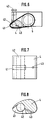
- FIG. 1 shows the strap 6 of the pneumatic compression device, which perforation breakthroughs 61, in the following Called compression holes 61, through a groove 62 are connected to each other.
- the groove 62 is strong drawn enlarged. Its width is based on the mass matched the fibers, which are summarized by the compression holes 61 become.
- the combined fibers lay in the groove 62, which is dimensioned so that it has a certain Clamping effect on the fibers. This will make the bundled Fibers up to the clamping line of the delivery cylinder 5 mechanically held so that the suction air flow only on bundling immediately after the outlet from the pair of output rollers the drafting system needs to be turned off.
- a single groove 62 would be closed wide and would not have a clamping effect, on the other hand too narrow a groove 62 will not be able to make the mass of coarser To catch yarn.
- the fiber mass only lies in the fine yarn middle groove. The outer grooves remain free. But with that always achieved sufficient clamping.
- the grooves 62 are also arranged symmetrically to the region of the compression holes 61.
- FIGs 3 and 4 straps 60, 600 are shown, in which in addition to the compression holes 61 perforations 63 are shown, their extent transverse to the fiber transport direction is larger than in the fiber transport direction.
- Cross holes 63 is the compression device in capable of coarse compaction with particularly wide fiber dressings to effect.
- the fibers are still bundled even when they are traversed the position of the fiber structure changes.
- the transverse extent this transverse holes 63 therefore suitably corresponds about the traversing stroke or the position of the Fiber dressing opposite the straps 6.
- Cross holes 63 and Compression holes 61 are arranged in alternation.
- the strap 60 in FIG. 3 is between two compression holes a transverse hole arranged. Cheaper for that However, air consumption is when the number of cross holes 63 is less than the number of compression holes 61. For example 4 is in each case in the strap 600 Transverse hole 63 arranged following two compression holes 61. This way, with low air consumption and traversing of the fiber structure achieved good compaction.
- Fig. 6 shows an embodiment in which the groove 41 in the strappy cage 4 are only less than half the length of strappy cage 4 extends.
- the to the suction line 42nd Connected groove 41 lies in the delivery cylinder 5 facing away Part of the strappy cage 4 and is to the output cylinder of the drafting system open.
- the length of this suction zone is about 10 to 25 mm.
- the suction zone can therefore be as short as possible to save suction air performance be held, i.e. it is only as long as it is for the summary of the fibers is absolutely necessary.
- the distance between the cylinder clamping lines is corresponding the stack length larger. Even then, the suction zone does not have to be larger his. Following the suction zone, gffs then take over. the grooves 62 in the straps 6 the cohesion or the clamping the combined fibers as already described above.
- Additional densification can also take place between the suction zone defined by the groove 41 and the clamping line of the delivery cylinder 5.
- a channel 43 is provided for this purpose, the groove 41 with the post-compression area before Delivery cylinder 5 connects.
- 11 and 12 is an alternative embodiment of the compression device shown at which two perforations 61 and 61 'and 63 and 63' are provided.
- the perforation 61 ', 63' also include the perforation holes Grooves 62 connected.
- 3 and 4 are here summarized, however, is due to the asymmetrical arrangement the groove 410 in the strappy cage 40 always only one of the rows of perforations in operation.
- the groove 410 is via a suction line 420 connected to the suction, not shown.
- This version has the advantage that by reversing the Strappy 660 the compacting device in a simple manner adapted to different sliver strengths and material requirements can be.
- the strap 660 can thus be used more flexibly as a strap with only one row of perforations.
- the suction in the fiber bundling zone is in for a long time Operation, it can not be prevented that in the groove 41st Collect fiber fly and dust and clog the airways be so that the operation of the pneumatic compression device is gradually impaired.
- the usual traveling blowers in ring spinning machines carry out satisfactory cleaning, as this is only on the outside are effective.
- a cleaning of the pneumatic compression device disassembly is very expensive.
- FIGS. 9 and 10 show an embodiment in which a cleaning device for the compression device is provided.
- a blown air line 45 with a connecting piece 44 opens into the groove 41 in the strappy cage 4 the mouth of the suction air line 42. Should a cleaning take place, so this compressed air line 45 compressed air initiated, but at the same time the negative pressure via the suction line 42 maintained. It has been shown that the Impurities that are mostly in the groove 41 and especially start at the mouth of the suction line 42, on this Way can be successfully eliminated.
- the compressed air is fed to the connecting piece 44. This can be done by hand, however also done by a walking machine.
- the suction effect can also be reduced if that the perforation is clogged by dust deposits. Also can cause burrs on the edges of the perforation Hang the fibers on it.
- burr-free perforation is problem-free works even with very dirty material without clogging.
- Such a burr-free perforation is caused by breaking the edges conveniently achieved by the usual punching process usually have a burr.
Landscapes
- Engineering & Computer Science (AREA)
- Mechanical Engineering (AREA)
- Textile Engineering (AREA)
- Spinning Or Twisting Of Yarns (AREA)
Applications Claiming Priority (7)
| Application Number | Priority Date | Filing Date | Title |
|---|---|---|---|
| DE19709580 | 1997-03-08 | ||
| DE19709580 | 1997-03-08 | ||
| DE19719773 | 1997-05-10 | ||
| DE19719773 | 1997-05-10 | ||
| DE19722528A DE19722528C2 (de) | 1997-03-08 | 1997-05-30 | Doppelriemchen-Streckwerk |
| DE19722528 | 1997-05-30 | ||
| EP98102622A EP0863233B1 (fr) | 1997-03-08 | 1998-02-16 | Dispositif d'étirage à double manchon |
Related Parent Applications (1)
| Application Number | Title | Priority Date | Filing Date |
|---|---|---|---|
| EP98102622A Division EP0863233B1 (fr) | 1997-03-08 | 1998-02-16 | Dispositif d'étirage à double manchon |
Publications (3)
| Publication Number | Publication Date |
|---|---|
| EP1191136A2 true EP1191136A2 (fr) | 2002-03-27 |
| EP1191136A3 EP1191136A3 (fr) | 2002-11-20 |
| EP1191136B1 EP1191136B1 (fr) | 2004-09-15 |
Family
ID=27217189
Family Applications (4)
| Application Number | Title | Priority Date | Filing Date |
|---|---|---|---|
| EP98102622A Expired - Lifetime EP0863233B1 (fr) | 1997-03-08 | 1998-02-16 | Dispositif d'étirage à double manchon |
| EP01129185A Expired - Lifetime EP1191135B1 (fr) | 1997-03-08 | 1998-02-16 | Courroies pour banc à étirer à courroies doublées |
| EP01129184A Expired - Lifetime EP1191134B1 (fr) | 1997-03-08 | 1998-02-16 | Courroies pour bancs à étirer à courroies doublées |
| EP01129186A Expired - Lifetime EP1191136B1 (fr) | 1997-03-08 | 1998-02-16 | Courroies pour banc à étirer à courroies doublées |
Family Applications Before (3)
| Application Number | Title | Priority Date | Filing Date |
|---|---|---|---|
| EP98102622A Expired - Lifetime EP0863233B1 (fr) | 1997-03-08 | 1998-02-16 | Dispositif d'étirage à double manchon |
| EP01129185A Expired - Lifetime EP1191135B1 (fr) | 1997-03-08 | 1998-02-16 | Courroies pour banc à étirer à courroies doublées |
| EP01129184A Expired - Lifetime EP1191134B1 (fr) | 1997-03-08 | 1998-02-16 | Courroies pour bancs à étirer à courroies doublées |
Country Status (8)
| Country | Link |
|---|---|
| US (2) | US6112509A (fr) |
| EP (4) | EP0863233B1 (fr) |
| JP (3) | JP4212008B2 (fr) |
| CN (2) | CN1082574C (fr) |
| BR (1) | BR9807481A (fr) |
| DE (7) | DE19758759B4 (fr) |
| ES (4) | ES2212789T3 (fr) |
| TR (1) | TR199800394A3 (fr) |
Families Citing this family (7)
| Publication number | Priority date | Publication date | Assignee | Title |
|---|---|---|---|---|
| DE19914201A1 (de) * | 1999-03-29 | 2000-10-05 | Zinser Textilmaschinen Gmbh | Verfahren und Vorrichtung zum Bündeln eines in einem Streckwerk einer Spinnereimaschine verzogenen Faserverbundes |
| JP2005023430A (ja) * | 2001-04-11 | 2005-01-27 | Toyota Industries Corp | 繊維束集束装置 |
| DE102007003525A1 (de) * | 2007-01-19 | 2008-07-31 | Spindelfabrik Suessen Gmbh | Saugkanal für eine Faserbündelungseinrichtung |
| DE102007042658A1 (de) | 2007-09-10 | 2009-03-12 | Cetex Institut für Textil- und Verarbeitungsmaschinen gemeinnützige GmbH | Verfahren und Vorrichtung zur Bearbeitung von Riemchen für Spinnereimaschinenstreckwerke mit Verdichtungseinrichtung |
| CN102449212B (zh) * | 2009-03-31 | 2015-03-18 | 奥斯德立克家用纺织品工业及贸易有限公司 | 纤维牵伸机构和其方法 |
| KR20130049767A (ko) * | 2010-03-19 | 2013-05-14 | 신닛테츠 수미킨 가가쿠 가부시키가이샤 | 금속 미립자 복합체 |
| DE102018006100A1 (de) * | 2018-08-03 | 2020-02-06 | Saurer Spinning Solutions Gmbh & Co. Kg | Streckwerkeinheit und Streckwerk für eine Spinnmaschine |
Family Cites Families (21)
| Publication number | Priority date | Publication date | Assignee | Title |
|---|---|---|---|---|
| DE882066C (de) | 1947-11-01 | 1953-07-06 | Warner Swasey Co | Streckwerk |
| BE511546A (fr) * | 1951-10-23 | |||
| US2774995A (en) | 1951-10-26 | 1956-12-25 | Warner Swasey Co | High reduction fiber drafting |
| FR1117278A (fr) * | 1954-12-22 | 1956-05-22 | Machines pour procédé d'étirage à grand coefficient | |
| US3122794A (en) * | 1961-02-14 | 1964-03-03 | Deering Milliken Res Corp | Drafting and scavenging apparatus |
| NL275433A (fr) * | 1961-03-06 | 1900-01-01 | ||
| GB997845A (en) * | 1963-03-08 | 1965-07-07 | Maremont Corp | Improvements in or relating to textile fibre processing apparatus |
| CH417420A (fr) * | 1963-08-14 | 1966-07-15 | Deering Milliken Res Corp | Appareil pour l'étirage de fibres textiles |
| US3438094A (en) * | 1966-09-02 | 1969-04-15 | Du Pont | High speed drafting process |
| US4290170A (en) * | 1980-03-27 | 1981-09-22 | Union Carbide Corporation | Device for aligning the attenuating fiber mats |
| DE3016409A1 (de) * | 1980-04-29 | 1981-11-05 | W. Schlafhorst & Co, 4050 Mönchengladbach | Walzenstreckwerk mit einer faserfuehrungsvorrichtung im hauptverzugsfeld |
| DE3839413A1 (de) * | 1988-11-22 | 1990-05-23 | Rieter Ag Maschf | Trichteranordnung am ausgang einer karde |
| DE3927739A1 (de) * | 1989-08-23 | 1991-02-28 | Fritz Stahlecker | Verfahren und vorrichtung zum falschdrallspinnen |
| US5243813A (en) * | 1989-10-04 | 1993-09-14 | Fritz Stahlecker | Process and an arrangement for false-twist spinning |
| DE3939776A1 (de) * | 1989-12-01 | 1991-06-06 | Fritz Stahlecker | Vorrichtung zum falschdrallspinnen |
| DE3939777A1 (de) * | 1989-12-01 | 1991-06-06 | Fritz Stahlecker | Vorrichtung zum falschdrallspinnen |
| DE4323472C2 (de) * | 1993-07-14 | 1997-08-07 | Inst F Textil Und Verfahrenste | Doppelriemchen-Streckwerk |
| US5648140A (en) * | 1995-06-06 | 1997-07-15 | Masonite Corporation | Conveyor and method for continuous vacuum lamination |
| US5706994A (en) * | 1995-06-26 | 1998-01-13 | Marquip, Inc. | Vacuum assisted web drive for corrugator double backer |
| DE29600417U1 (de) * | 1996-01-11 | 1996-03-07 | Zinser Textilmaschinen Gmbh, 73061 Ebersbach | Streckwerk für eine Spinnereimaschine |
| US5819907A (en) * | 1996-07-15 | 1998-10-13 | Goldco Industries, Inc. | Apparatus and method for conveying different types of force responsive articles |
-
1997
- 1997-05-30 DE DE19758759A patent/DE19758759B4/de not_active Expired - Fee Related
- 1997-05-30 DE DE19758758A patent/DE19758758C2/de not_active Expired - Fee Related
- 1997-05-30 DE DE19758757A patent/DE19758757C2/de not_active Expired - Fee Related
-
1998
- 1998-02-16 ES ES01129185T patent/ES2212789T3/es not_active Expired - Lifetime
- 1998-02-16 EP EP98102622A patent/EP0863233B1/fr not_active Expired - Lifetime
- 1998-02-16 EP EP01129185A patent/EP1191135B1/fr not_active Expired - Lifetime
- 1998-02-16 DE DE59811969T patent/DE59811969D1/de not_active Expired - Lifetime
- 1998-02-16 ES ES01129184T patent/ES2215104T3/es not_active Expired - Lifetime
- 1998-02-16 EP EP01129184A patent/EP1191134B1/fr not_active Expired - Lifetime
- 1998-02-16 EP EP01129186A patent/EP1191136B1/fr not_active Expired - Lifetime
- 1998-02-16 DE DE59810426T patent/DE59810426D1/de not_active Expired - Lifetime
- 1998-02-16 ES ES98102622T patent/ES2196411T3/es not_active Expired - Lifetime
- 1998-02-16 ES ES01129186T patent/ES2227050T3/es not_active Expired - Lifetime
- 1998-02-16 DE DE59810641T patent/DE59810641D1/de not_active Expired - Fee Related
- 1998-02-16 DE DE59808211T patent/DE59808211D1/de not_active Expired - Lifetime
- 1998-02-26 US US09/031,567 patent/US6112509A/en not_active Expired - Fee Related
- 1998-03-06 TR TR1998/00394A patent/TR199800394A3/tr unknown
- 1998-03-06 BR BR9807481-4A patent/BR9807481A/pt not_active Application Discontinuation
- 1998-03-07 CN CN98107394A patent/CN1082574C/zh not_active Expired - Fee Related
- 1998-03-09 JP JP05676698A patent/JP4212008B2/ja not_active Expired - Fee Related
-
2000
- 2000-07-10 US US09/613,347 patent/US6370737B1/en not_active Expired - Fee Related
-
2001
- 2001-12-15 CN CNB011437235A patent/CN1252331C/zh not_active Expired - Fee Related
-
2004
- 2004-11-19 JP JP2004335768A patent/JP2005089961A/ja active Pending
- 2004-11-19 JP JP2004335755A patent/JP4212054B2/ja not_active Expired - Fee Related
Also Published As
Similar Documents
| Publication | Publication Date | Title |
|---|---|---|
| EP0635590B1 (fr) | Dispositif d'étirage à double manchon | |
| EP2865794B1 (fr) | Métier à filer | |
| DE19837182B4 (de) | Transportband zum Transportieren eines zu verdichtenden Faserverbandes | |
| EP0964945B1 (fr) | Systeme d'etirage pour metiers a filer comportant une zone de mise en faisceaux de fibres et metier a anneau ainsi equipe | |
| EP1191136B1 (fr) | Courroies pour banc à étirer à courroies doublées | |
| EP1302572A2 (fr) | Métier à filer pour la réalisation de files comportant une âme | |
| DE19722528C2 (de) | Doppelriemchen-Streckwerk | |
| EP0924323B1 (fr) | Dispositif d'étirage pour des métiers à filer | |
| DE19949666A1 (de) | Vorrichtung zum Verdichten eines Faserverbandes | |
| DE602005006163T2 (de) | Kämmmaschine für Baumwolle und dergleichen mit verbesserter Vorrichtung zur Faserbandformung | |
| WO2002034976A1 (fr) | Bande transporteuse servant a transporter un assemblage de fibres a comprimer | |
| DE10137004A1 (de) | Spinnmaschine mit einer Vielzahl von Spinnstellen | |
| DE10146608A1 (de) | Luftspinnvorrichtung | |
| DE102019128326A1 (de) | Verdichtungsvorrichtung für ein Streckwerk einer Spinnmaschine sowie Streckwerk für eine Verdichtungsvorrichtung | |
| DE10106891A1 (de) | Spinnmaschine mit einer Vielzahl von Spinnstellen | |
| EP3741889B1 (fr) | Guide condenseur pour un métier à filer, banc d'étirage pourvu du guide condenseur et procédé de fonctionnement du guide condenseur | |
| DE19805396B4 (de) | Spinnmaschine mit Verdichtungseinrichtung | |
| DE10054613A1 (de) | Spinnmaschine mit einer Verdichtungseinrichtung | |
| DE10106771A1 (de) | Spinnmaschine mit einer Vielzahl von Spinnstellen | |
| DE9422313U1 (de) | Doppelriemchen-Streckwerk | |
| DE102023118453A1 (de) | Luftspinnmaschine mit einer Vielzahl nebeneinander angeordneter Spinnstellen | |
| CH519031A (de) | Absaugeinrichtung zum Entfernen von Unreinigkeiten und Flug bei Krempelmaschine | |
| DE10022747A1 (de) | Spinnmaschine mit einer Vielzahl von Spinnstellen | |
| DE10130560A1 (de) | Spinnvorrichtung | |
| DE10045654A1 (de) | Vorrichtung zum Verdichten eines Faserverbandes |
Legal Events
| Date | Code | Title | Description |
|---|---|---|---|
| PUAI | Public reference made under article 153(3) epc to a published international application that has entered the european phase |
Free format text: ORIGINAL CODE: 0009012 |
|
| AC | Divisional application: reference to earlier application |
Ref document number: 863233 Country of ref document: EP |
|
| AK | Designated contracting states |
Kind code of ref document: A2 Designated state(s): CH DE ES FR IT LI |
|
| RIN1 | Information on inventor provided before grant (corrected) |
Inventor name: DR.-ING.ARTZT, PETER Inventor name: ZOUDLIK, HOLGER DIPL.-ING. |
|
| PUAL | Search report despatched |
Free format text: ORIGINAL CODE: 0009013 |
|
| RIC1 | Information provided on ipc code assigned before grant |
Free format text: 7D 01H 5/86 A, 7D 01H 5/72 B, 7D 01H 5/26 B |
|
| AK | Designated contracting states |
Kind code of ref document: A3 Designated state(s): CH DE ES FR IT LI |
|
| 17P | Request for examination filed |
Effective date: 20021121 |
|
| 17Q | First examination report despatched |
Effective date: 20030410 |
|
| AKX | Designation fees paid |
Designated state(s): CH DE ES FR IT LI |
|
| GRAP | Despatch of communication of intention to grant a patent |
Free format text: ORIGINAL CODE: EPIDOSNIGR1 |
|
| GRAS | Grant fee paid |
Free format text: ORIGINAL CODE: EPIDOSNIGR3 |
|
| GRAA | (expected) grant |
Free format text: ORIGINAL CODE: 0009210 |
|
| AC | Divisional application: reference to earlier application |
Ref document number: 0863233 Country of ref document: EP Kind code of ref document: P |
|
| AK | Designated contracting states |
Kind code of ref document: B1 Designated state(s): CH DE ES FR IT LI |
|
| PG25 | Lapsed in a contracting state [announced via postgrant information from national office to epo] |
Ref country code: FR Free format text: LAPSE BECAUSE OF FAILURE TO SUBMIT A TRANSLATION OF THE DESCRIPTION OR TO PAY THE FEE WITHIN THE PRESCRIBED TIME-LIMIT Effective date: 20040915 |
|
| REG | Reference to a national code |
Ref country code: CH Ref legal event code: EP |
|
| RIN1 | Information on inventor provided before grant (corrected) |
Inventor name: ARTZT, PETER, DR.-ING. Inventor name: ZOUDLIK, HOLGER, DIPL.-ING. |
|
| REF | Corresponds to: |
Ref document number: 59811969 Country of ref document: DE Date of ref document: 20041021 Kind code of ref document: P |
|
| REG | Reference to a national code |
Ref country code: ES Ref legal event code: FG2A Ref document number: 2227050 Country of ref document: ES Kind code of ref document: T3 |
|
| PLBE | No opposition filed within time limit |
Free format text: ORIGINAL CODE: 0009261 |
|
| STAA | Information on the status of an ep patent application or granted ep patent |
Free format text: STATUS: NO OPPOSITION FILED WITHIN TIME LIMIT |
|
| 26N | No opposition filed |
Effective date: 20050616 |
|
| EN | Fr: translation not filed | ||
| PGFP | Annual fee paid to national office [announced via postgrant information from national office to epo] |
Ref country code: ES Payment date: 20080225 Year of fee payment: 11 |
|
| REG | Reference to a national code |
Ref country code: ES Ref legal event code: FD2A Effective date: 20090217 |
|
| PG25 | Lapsed in a contracting state [announced via postgrant information from national office to epo] |
Ref country code: ES Free format text: LAPSE BECAUSE OF NON-PAYMENT OF DUE FEES Effective date: 20090217 |
|
| PGFP | Annual fee paid to national office [announced via postgrant information from national office to epo] |
Ref country code: DE Payment date: 20130408 Year of fee payment: 16 |
|
| PGFP | Annual fee paid to national office [announced via postgrant information from national office to epo] |
Ref country code: CH Payment date: 20140227 Year of fee payment: 17 |
|
| PGFP | Annual fee paid to national office [announced via postgrant information from national office to epo] |
Ref country code: IT Payment date: 20140219 Year of fee payment: 17 |
|
| REG | Reference to a national code |
Ref country code: DE Ref legal event code: R119 Ref document number: 59811969 Country of ref document: DE |
|
| REG | Reference to a national code |
Ref country code: DE Ref legal event code: R119 Ref document number: 59811969 Country of ref document: DE Effective date: 20140902 |
|
| PG25 | Lapsed in a contracting state [announced via postgrant information from national office to epo] |
Ref country code: DE Free format text: LAPSE BECAUSE OF NON-PAYMENT OF DUE FEES Effective date: 20140902 |
|
| REG | Reference to a national code |
Ref country code: CH Ref legal event code: PL |
|
| PG25 | Lapsed in a contracting state [announced via postgrant information from national office to epo] |
Ref country code: LI Free format text: LAPSE BECAUSE OF NON-PAYMENT OF DUE FEES Effective date: 20150228 Ref country code: CH Free format text: LAPSE BECAUSE OF NON-PAYMENT OF DUE FEES Effective date: 20150228 |
|
| PG25 | Lapsed in a contracting state [announced via postgrant information from national office to epo] |
Ref country code: IT Free format text: LAPSE BECAUSE OF NON-PAYMENT OF DUE FEES Effective date: 20150216 |