EP1191296A2 - Arrangement de circuit pour tour de refroidissement à circuit fermé - Google Patents
Arrangement de circuit pour tour de refroidissement à circuit fermé Download PDFInfo
- Publication number
- EP1191296A2 EP1191296A2 EP01307954A EP01307954A EP1191296A2 EP 1191296 A2 EP1191296 A2 EP 1191296A2 EP 01307954 A EP01307954 A EP 01307954A EP 01307954 A EP01307954 A EP 01307954A EP 1191296 A2 EP1191296 A2 EP 1191296A2
- Authority
- EP
- European Patent Office
- Prior art keywords
- manifold
- chamber
- segment
- fluid
- circuit
- Prior art date
- Legal status (The legal status is an assumption and is not a legal conclusion. Google has not performed a legal analysis and makes no representation as to the accuracy of the status listed.)
- Withdrawn
Links
- 238000001816 cooling Methods 0.000 title claims abstract description 60
- 239000012530 fluid Substances 0.000 claims description 82
- 238000012546 transfer Methods 0.000 claims description 16
- 238000004891 communication Methods 0.000 claims description 12
- 239000007921 spray Substances 0.000 claims description 12
- 230000008878 coupling Effects 0.000 claims description 7
- 238000010168 coupling process Methods 0.000 claims description 7
- 238000005859 coupling reaction Methods 0.000 claims description 7
- 239000007788 liquid Substances 0.000 claims description 6
- 239000011800 void material Substances 0.000 claims 2
- XLYOFNOQVPJJNP-UHFFFAOYSA-N water Substances O XLYOFNOQVPJJNP-UHFFFAOYSA-N 0.000 abstract description 33
- 230000000712 assembly Effects 0.000 abstract description 6
- 238000000429 assembly Methods 0.000 abstract description 6
- 238000000034 method Methods 0.000 description 9
- 239000003595 mist Substances 0.000 description 7
- 230000008569 process Effects 0.000 description 6
- 230000000694 effects Effects 0.000 description 3
- 230000004048 modification Effects 0.000 description 3
- 238000012986 modification Methods 0.000 description 3
- WYTGDNHDOZPMIW-RCBQFDQVSA-N alstonine Natural products C1=CC2=C3C=CC=CC3=NC2=C2N1C[C@H]1[C@H](C)OC=C(C(=O)OC)[C@H]1C2 WYTGDNHDOZPMIW-RCBQFDQVSA-N 0.000 description 2
- 230000004075 alteration Effects 0.000 description 2
- 230000008901 benefit Effects 0.000 description 2
- 230000001419 dependent effect Effects 0.000 description 2
- 238000013461 design Methods 0.000 description 2
- 238000007599 discharging Methods 0.000 description 2
- 238000001704 evaporation Methods 0.000 description 2
- 238000013459 approach Methods 0.000 description 1
- 238000003491 array Methods 0.000 description 1
- 235000019628 coolness Nutrition 0.000 description 1
- 238000011161 development Methods 0.000 description 1
- 230000018109 developmental process Effects 0.000 description 1
- 230000008020 evaporation Effects 0.000 description 1
- 238000004321 preservation Methods 0.000 description 1
- 230000008707 rearrangement Effects 0.000 description 1
- 230000009467 reduction Effects 0.000 description 1
- 238000000926 separation method Methods 0.000 description 1
- 238000005507 spraying Methods 0.000 description 1
- 238000009834 vaporization Methods 0.000 description 1
- 230000008016 vaporization Effects 0.000 description 1
Images



Classifications
-
- F—MECHANICAL ENGINEERING; LIGHTING; HEATING; WEAPONS; BLASTING
- F28—HEAT EXCHANGE IN GENERAL
- F28D—HEAT-EXCHANGE APPARATUS, NOT PROVIDED FOR IN ANOTHER SUBCLASS, IN WHICH THE HEAT-EXCHANGE MEDIA DO NOT COME INTO DIRECT CONTACT
- F28D5/00—Heat-exchange apparatus having stationary conduit assemblies for one heat-exchange medium only, the media being in contact with different sides of the conduit wall, using the cooling effect of natural or forced evaporation
- F28D5/02—Heat-exchange apparatus having stationary conduit assemblies for one heat-exchange medium only, the media being in contact with different sides of the conduit wall, using the cooling effect of natural or forced evaporation in which the evaporating medium flows in a continuous film or trickles freely over the conduits
Definitions
- the present invention provides a coil tube or circuit arrangement for a closed circuit cooling tower. More specifically, a coil tube assembly for a cooling tower, which is usually a counterflow closed-circuit cooling tower, has a coil tube assembly with a plurality of coil circuits.
- the disclosed method of circuiting the coil assembly for closed-circuit cooling towers gives an enhanced performance, and more particularly enhanced performance for coil assemblies operating at low internal fluid flow.
- the circuits are provided between an upper header with a fluid inlet nozzle to a lower header with a fluid outlet nozzle.
- the individual circuits extend from the upper header to the lower header in a serpentine arrangement, which may be generally described as a series of parallel straight tube lengths connected by u-shaped bends. Fluid has historically been communicated from the top of the coil tube assembly, or upper header, to the lower header by traversing the plurality of parallel tube lengths.
- the fluid to be cooled is circulated inside the tubes of the units heat exchanger. Heat flows from the process fluid through the coil tube wall to the water cascading over the tubes from the spray-water distribution system. Air is forced upward over the coil, evaporating a small percentage of the water, absorbing the latent heat of vaporization and discharging the heat to the atmosphere. The remaining water is recovered in the tower sump for recirculation to the water spray. Water entrained in the air stream is recaptured in mist eliminators at the unit discharge and returned to the sump. It is also known that the water distribution system can be shut off and the unit may be run dry. Air is still forced upward over the coil, but the heat is now solely dissipated to the atmosphere by sensible cooling.
- U.S. Patent No. 4,196,157 to Schinner teaches a separation arrangement between the adjacent tubes of a coil assembly.
- the structural arrangement of a typical closed-circuit cooling tower structure is noted in the text.
- the typical feed arrangement for the fluid to be cooled is taught and illlustrated in this patent with an upper and inlet manifold for receipt of warm fluid for cooling, a lower and outlet manifold for discharge of cooler fluid, and the connection of the serpentine tube assembly therebetween coupling the inlet and outlet manifold.
- This is an exemplary teaching of the understanding of heat transfer and maximum expected cooling for closed-circuit cooling towers in the prior art.
- the present invention provides a coil tube or circuit arrangement for a closed circuit cool ing tower as defined by the attached claims and provides means for recovering the plenum-area, spray-water cooling effect between about the bottom of the cooling coil and the water in the sump.
- the tube bundles and their layout are generally consistent with prior practice for the purposes of maintaining the structural arrangement of the cooling-tower housing footprint
- the direction of fluid flow through the tubing has been reconfigured to provide the last leg or segment of each circuit with fluid flow in the vertically upward direction.
- the upward flow in this last leg or segment takes advantage of the above-noted plenum-area cooling effect, or added cooling, provided below the coil assembly.
- the last leg in the coil is upwardly directed in concurrent flow with the flow of air to better utilize the available heat transfer/temperature reduction for the fluid to be cooled, without incurring any increased operating costs above those associated with current unit operating costs.
- the prior art generally utilizes inlet and outlet headers or manifolds, which facilitate the handling of multiple tubing structures, but it is known that individually piped arrangements could be configured to accommodate the routing of a tube to produce the directional flow required, and this limitation is considered to be included within the teaching of this application and the use of manifolds to more expeditiously accomplish this task.
- the present invention provides reconfiguration of the coil assemblies in closed-circuit cooling towers illustrated in Figure 1, and more particularly coil circuits for units operating at low internal fluid flows.
- fluid refers to gasses and liquids but is typically a liquid.
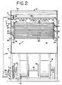
- the reconfigured layout of alternative arrangements are particularly noted in Figures 10 to 13, but the physical environment and typical position of the coil assemblies are illustrated in Figures 1 and 2.
- Closed-circuit cooling tower 11 of Figures 1 and 2 is illustrative of a counterflow structure, but is an exemplary illustration and not a limitation to the present invention. Cooling tower 11 has a generally vertical casing 10 with different levels within its interior, including mist eliminator 12, water spray assembly 14, coil assembly 16, fan assembly 18 and lower water trough or sump 20.
- Casing 10 has vertical front wall 24 and rear wall 22 in Figure 1 with side walls 26 and 28 noted in Figure 2. Diagonal wall 30 downwardly extends from front wall 24 to rear wall 22 to provide sump 20.
- Fan assembly 18 is positioned behind and below diagonal wall 30. The illustrated fan assembly 18 has a pair of centrifugal fans 32 with outlet cowls 34 projecting through wall 30 into conduit 13 above sump 20 but below coil assembly 16. Fan assembly 18 includes drive motor 42 and pulley 38 on common drive shaft 36, which pulley 38 and motor 42 are coupled by belt 40.
- Recirculation line 45 in Figure 2 extends through side wall 26 of housing 10 near the base of sump 20.
- Line 45 extends from sump 20 to recirculation pump 46, line 44 and subsequently to water-spray assembly 14 for communication of fluid for spraying over coil assembly 16.
- Water-spray assembly 14 has water box 48 extending along side wall 26 and a pair of distribution pipes 50 extending horizontally across the interior of housing 10 to opposite wall 28. Pipes 50 are fitted with a plurality of nozzles 52, which emit intersecting fan-shaped water sprays to provide an even distribution of water over coil assembly 16.
- the specific type or style of water spray assembly 14 and nozzle 52 is merely exemplary and not a limitation to the present invention.
- Mist eliminator 12 has a plurality of closely spaced elongated strips 54, which are bent along their length to form sinuous paths from the region of water spray assembly 14 through top 41 of housing 10. Mist eliminator 12 extends across substantially the entire cross-section of housing 10 at top 41.
- Coil assembly 16 is noted in Figures 1 and 2 with upper inlet manifold 56 and lower outlet manifold 58, which manifolds 56 and 58 extend horizontally across the upper interior conduit 15 adjacent side wall 26, as noted in Figures 2 to 4.
- Fluid inlet conduit or nozzle 62 and outlet conduit or nozzle 64 extend through side wall 26 and are connected with upper manifold 56 and lower manifold 58, respectively. These fluid nozzles are connected to receive a process fluid to be cooled.
- Coil assembly 16 has a plurality of typical circuits 66 connected between upper manifold 56 and lower manifold 58 in Figures 2 to 4.
- circuits 91 and 93 at front and rear walls 22 and 24 are only two of multiple circuits that would be provided to fill chamber 15 between walls 22 and 24.
- Each of these circuits 91 and 93 would extend between upper header 56 and lower header 58 or have an individual header not shown, which may depend upon the header design and the width of chamber 15.
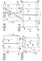
- Illustrative of the arrangement of two individual tube bundles and their related headers is the tube arrangement noted in Figure 8.
- Each typical circuit 66 in Figures 1 to 4 has a plurality of elongated segments 95 and is formed into a serpentine arrangement through 180°-bends 68 and 70 in Figure 4 near side walls 26 and 28.
- different segments 95 of each circuit 66 extend generally horizontally across the interior conduit 15 of housing 10 between side walls 26 and 28 at different levels in interior 15 along parallel vertical planes closely spaced to the plane of each of the other circuits 66.
- circuits 66 are arranged in alternately offset arrays with each individual straight length being located a short distance lower or higher than the individual straight lengths on each side of it.
- FIG. 5 illustrates a coil assembly arrangement 16 with two similar circuits 66 and 75 with their own headers 56, 58 in a parallel relationship in chamber 15 of a closed-circuit cooling tower 11.
- fluid-to-be-cooled flows into closed-circuit cooling tower 11 through inlet nozzle 62.
- This fluid, or process liquid is then distributed by upper manifold 56 to the upper ends of circuits 66 and it flows down through serpentine tube circuits 66 to lower manifold 68 for discharge from outlet nozzle 64.
- water is sprayed from spray nozzles 52 downward onto the outer surfaces of circuits 66 while air is simultaneously blown from fan 32 upward between circuits 66.
- the sprayed water is collected in sump 20 for recirculation to spray assembly 14.
- mist eliminator assembly 12 The upwardly flowing air passes through mist eliminator assembly 12 to capture entrained water and return it to sump 20 before exhausting the air from unit 11.
- fan 32 is noted at the lower portion of unit 11, it is known that such fans can be positioned at the tops of such units to pull air through the assembly, and the present assembly 11 is merely exemplary of a closed circuit unit 11 and not a limitation.
- the fluid-to-be-cooled passes downward through circuits 66 from upper manifold 56 to lower manifold 58, the fluid yields heat to the tube walls. This heat passes through the tube walls to the downward flowing water on the tube surface. As the water continues downward, it encounters the upwardly directed air and transfers heat to the air, both by sensible heat transfer and by latent heat transfer, that is by partial evaporation. The remaining water is collected in sump 20 for recirculation. A certain amount of water is entrained in the air as droplets, which are carried from coil assembly 16 and water spray assembly 14. However, as this water bearing air flow is transferred through mist eliminator assembly 12, the liquid droplets are separated from the air and are deposited on the elements of the mist eliminator. The water is then recovered in sump 20.
- a circuit arrangement with a pressure drop less than approximately three pounds per square inch could be considered for a half-circuit arrangement.
- a circuit arrangement with a pressure drop less than approximately one pound per square inch could be considered for utilization of a one-third circuit arrangement.
- FIGs 5 to 13 are schematic end-connection views of tube bundles similar to the illustration of coil assembly in Figure 4.
- coil assembly 16 is undivided and the process-fluid flow direction is noted from top to bottom by typical circuit 66.
- coil assembly 16 is split such that a first group of circuits 65 is connected by crossover pipe 80 to a second group of circuits 67.
- Upper manifold 56 is now provided in a two-section arrangement with first section 51 and second section 53 separated by divider 71.
- lower manifold 58 has been divided by divider 73 into third section 55 and fourth section 57.
- upper manifold 56 and lower manifold 58 permits fluid flow between upper and lower manifolds, subsequent flow from lower manifold 58 to upper manifold 56 and final discharge at fourth section 57 of lower manifold 58.
- This inter-manifold fluid transfer permits the fluid-to-be-cooled to flow in series through typical circuits 65 and 67 counter to the air flow in chamber 15.
- FIG 7 a second alternative circuiting arrangement, which may be referred to as a one-third circuit assembly, is shown with typical circuit 66 of coil assembly 16 noted in Figure 5 having first segment 65, second segment 67 and third segment 69.
- lower-manifold third section 55 acts as a conduit to transfer process fluid between first segment 65 and second segment 67, which fluid is transferred through second segment 67 to upper-manifold second section 53.
- second upper-manifold section 53 acts as a conduit to transfer fluid to third segment 69.
- the fluid is transferred through third segment 69 to lower-manifold fourth section 57 and discharge nozzle 64.
- the fluid-to-be-cooled is exposed to counterflowing air through first segment 65 and third segment 69.
- the fluid flow in the figures is noted by arrows on typical circuits 66 and the several noted segments 65, 67 and 69.
- the fluid in typical circuits 66 is exposed to counterflow air in two segments with the expectation that this will further cool the fluid in the segments before its discharge from nozzle 64.
- there are physical fluid dynamic losses from such arrangements including changes in fluid velocity and significant pressure drops from inlet nozzle 62 to outlet nozzle 64.
- the half-circuited arrangement of Figure 6 may experience a pressure drop approximately seven times greater than the pressure drop of assembly of Figure 5.
- the one-third circuit of Figure 7 can be expected to experience a pressure drop of approximately twenty-one times the pressure drop experienced in a standard coil assembly as illustrated in Figure 5.
- the internal heat-transfer efficiency of coil assembly 16 increases. The consequent greater pressure drop would be tolerated where the initial pressure drop in a conventional coil arrangement was relatively low.
- Figure 8 shows a coil assembly 16 having individual typical circuits 66 and 75 extending between upper manifold 56 and lower manifold 58 with individual inlet nozzles 62 and outlet nozzles 64.
- the individual circuits 66 and 75 have been provided in series by coupling crossover pipe 80 between discharge nozzle 64 of circuit 66 and inlet nozzle 62 of circuit 75.
- FIG 10 is an illustration of a coil assembly 16 with a typical circuit 66, which has been half-circuited.
- This Figure illustrates the most fundamental case of a closed-circuit cooling tower 11 where upper manifold 56 has been divided into first section 51 with inlet nozzle 62 and second section 53 with outlet nozzle 64.
- Coil assembly 16 including circuit 66 is positioned in chamber 15 and has inlet nozzle 62 and outlet nozzle 64 in upper manifold 56, which has been divided into first section 51 and second section 53 by divider 73.
- a fluid outlet nozzle 64 in lower manifold 58 has been sealed or is not present
- Lower manifold 58 can now be characterized as a conduit communicating fluid between first segment 65 and second segment 67.
- air flow is communicated through chamber 15 vertically upward as noted in Figures 1 and 2.
- process-fluid flow in segments 65 and 67 is exposed to air flow in both segments 65 and 67.
- process fluid flow in segment 65 is counterflow with the air flow, and in segment 67 it is in parallel concurrent flow with the air flow.
- Figure 11 illustrates a two-coil arrangement that has been half-circuited, that is two typical circuits 66 have been joined in a series connection. More specifically first circuit 66 is noted as segment 65, and second circuit 66 is noted as segment 67 in this arrangement, which segments 65 and 67 were originally independent circuits each with an inlet nozzle 62 in upper manifold 56 and an outlet nozzle 64 in lower manifold 58. However, in this illustration, the nozzles in lower manifolds 58 are coupled by external crossover pipe 80. Thus, inlet port 62 and upper manifold 56 are coupled to lower manifold 58 by segment 65.
- Lower manifolds 58 and crossover pipe 80 now function as a conduit between first segment 65 and second segment 67, which segment is connected between lower manifold 58 and outlet nozzle 64 in upper manifold 56.
- fluid flow in final segment 67 is again provided in a concurrent direction with the air flow noted at arrow 81, and communicates from lower section 17 of chamber 15 at the final segment transfer.
- Lower section 17 is noted in Figure 1 of closed-circuit cooling tower 11.
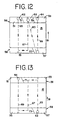
- Figure 12 illustrates an alternative embodiment or tube arrangement wherein typical circuit 66 is provided as a one-third circuit coil assembly.
- upper manifold 56 has first divider 71 and third divider 79 while lower manifold 58 has second divider 73.
- lower manifold 58 has third section 55 and fourth section 57, which is consistent with the illustration of Figure 6.
- upper manifold 56 now includes first section 51, second section 53 and fifth section 59, which also includes outlet nozzle 64.
- inlet nozzle 62 and first section 51 are connected to lower manifold third section 55 by segment 65.
- Second segment 67 couples second upper-manifold section 53 and lower-manifold third section 55, where lower manifold section 55 acts as a conduit between segments 65 and 67.
- Crossover pipe 80 in this arrangement couples segment 67 at upper-manifold, second section 53 to segment 69 at lower-manifold, fourth-section 57, which crossover pipe 80 may be noted as an external pipe section. Subsequently, segment 69 communicates fluid from lower-manifold fourth-section 57 to upper-manifold, fifth section 59 and outlet nozzle 64. In this configuration of Figure 12, final segment 69 provides fluid flow in a concurrent direction with the air flowing through chamber 15, as noted by arrow 81.
- Figure 13 illustrates a second alternative embodiment wherein typical circuit 66 is provided as a one-third circuit coil assembly.
- upper manifold 56 has first divider 71, which again divides manifold 56 into first section 51 and second section 53.
- Lower manifold 58 has second divider 73, which divides manifold 58 into third section 55 and fourth section 57.
- inlet nozzle 62 is positioned in fourth section 57 of lower manifold 58
- first segment 65 is connected between inlet nozzle 62 and second section 53 of upper manifold 56.
- Second segment 67 couples upper manifold, second section 53 and lower-manifold, third section 55 for transfer of fluid to third section 55 at lower end 17 of chamber 15.
- Third segment 69 is connected between lower-manifold, third section 55 and upper-manifold, first section 51 and outlet nozzle 64 for discharge of fluid.
- upper-manifold section 53 serves as a conduit between first segment 65 and second segment 67.
- lower-manifold segment 55 serves as a conduit between second segment 67 and third segment 69 for communication of fluid.
- both first and third segments 65 and 69 provide fluid flow in the same direction as the air flow noted at arrow 81, and thus final segment 69 provides fluid flow in the air-flow direction from lower region 17 of chamber 15.
- closed-circuit cooling tower 11 appears as a standard operating system.
- the present invention more fully utilizes available cooling capacity, which was previously underutilized, to reduce the temperature of the fluid to be cooled communicating through coil assembly 16 and typical circuits 66.
- the amount of increased cooling may be dependent upon the particular size of unit 11 and the operating parameters associated therewith, such as air flow velocity, fluid flow rate and pressure drop of the fluid.
- utilization of the available cooling and the reduced fluid outlet temperature can be provided at no increase in capital expenditure.
- increases in cooling are available for extant heat exchange units without increasing the structure sizes. It is acknowledged that there may be currently unrecognized unit-size or operating parameter limitations to take advantage of this heretofore unused capacity.
- this available cooling capacity may be readily utilized by relatively low-pressure drop, low process-fluid-velocity units 11, which low-pressure drop units 11 are known by these terms in the HVAC industry.
- the operable condition provides that the final circuit segment communicating to fluid outlet nozzle 64 in the above-shown examples is to be provided in a parallel flow direction with the air flow from the lower area 17 of plenum chamber 15.
- the positions of the mechanical operating equipment of the various systems, such as pump 46 and fan 32, may be changed as a design choice, but such changes are not required for the present invention.
- the alternative structures of Figures 12 and 13 clearly note that the position of inlet nozzle 62 may be accommodated by alternatives.
- the illustrations note only one or two manifolds in the side-by-side relationships of circuits or tube bundles 66, it is considered that these are demonstrative of coil assemblies 16 which may require multiple circuits 66 to fill chamber 15 in a typical closed-circuit cooling tower 11.
Landscapes
- Engineering & Computer Science (AREA)
- Physics & Mathematics (AREA)
- Thermal Sciences (AREA)
- Mechanical Engineering (AREA)
- General Engineering & Computer Science (AREA)
- Heat-Exchange Devices With Radiators And Conduit Assemblies (AREA)
Applications Claiming Priority (2)
| Application Number | Priority Date | Filing Date | Title |
|---|---|---|---|
| US668597 | 2000-09-22 | ||
| US09/668,597 US6574980B1 (en) | 2000-09-22 | 2000-09-22 | Circuiting arrangement for a closed circuit cooling tower |
Publications (2)
| Publication Number | Publication Date |
|---|---|
| EP1191296A2 true EP1191296A2 (fr) | 2002-03-27 |
| EP1191296A3 EP1191296A3 (fr) | 2004-04-21 |
Family
ID=24682988
Family Applications (1)
| Application Number | Title | Priority Date | Filing Date |
|---|---|---|---|
| EP01307954A Withdrawn EP1191296A3 (fr) | 2000-09-22 | 2001-09-18 | Arrangement de circuit pour tour de refroidissement à circuit fermé |
Country Status (6)
| Country | Link |
|---|---|
| US (1) | US6574980B1 (fr) |
| EP (1) | EP1191296A3 (fr) |
| CN (1) | CN1203287C (fr) |
| AU (1) | AU765388B2 (fr) |
| BR (1) | BR0104163B1 (fr) |
| CA (1) | CA2355219C (fr) |
Cited By (3)
| Publication number | Priority date | Publication date | Assignee | Title |
|---|---|---|---|---|
| ES2255345A1 (es) * | 2003-04-01 | 2006-06-16 | Torres Intercal, S.A. | Bateria tubular para torres de refrigeracion evaporativa con circuito cerrado. |
| WO2019046160A1 (fr) | 2017-08-31 | 2019-03-07 | Baltimore Aircoil Company, Inc. | Agencement collecteur d'eau |
| US11255620B2 (en) | 2016-09-30 | 2022-02-22 | Baltimore Aircoil Company, Inc. | Water collection/deflection arrangement |
Families Citing this family (20)
| Publication number | Priority date | Publication date | Assignee | Title |
|---|---|---|---|---|
| US20030136134A1 (en) * | 2002-01-18 | 2003-07-24 | Pun John Y. | Fluid and air heat exchanger and method |
| US7243909B2 (en) * | 2004-12-10 | 2007-07-17 | Koplin Edward C | Collector sump cooling tower |
| CN100529630C (zh) * | 2007-11-14 | 2009-08-19 | 中国科学技术大学 | 用于煤或生物质热解液化的喷雾与降膜复合式冷凝装置 |
| KR100931272B1 (ko) * | 2009-03-24 | 2009-12-11 | 주식회사 성지공조기술 | 모듈형 냉각탑 |
| US20120067546A1 (en) * | 2010-09-17 | 2012-03-22 | Evapco, Inc. | Hybrid heat exchanger apparatus and method of operating the same |
| US9303925B2 (en) * | 2012-02-17 | 2016-04-05 | Hussmann Corporation | Microchannel suction line heat exchanger |
| US10731881B2 (en) | 2013-01-11 | 2020-08-04 | Carrier Corporation | Fan coil unit with shrouded fan |
| CN108816702B (zh) * | 2018-06-28 | 2020-03-31 | 清华大学 | 一种具有超疏-超亲水结构的自驱动集水表面及制备方法 |
| ES3029136T3 (en) | 2019-03-19 | 2025-06-23 | Baltimore Aircoil Co Inc | Heat exchanger having plume abatement assembly bypass |
| DE102019110236A1 (de) * | 2019-04-18 | 2020-10-22 | Güntner Gmbh & Co. Kg | Wärmeübertrageranordnung mit wenigstens einem Mehrpass-Wärmeübertrager und Verfahren zum Betrieb einer Wärmeübertrageranordnung |
| DE102019110237A1 (de) | 2019-04-18 | 2020-10-22 | Güntner Gmbh & Co. Kg | Wärmeübertrageranordnung mit wenigstens einem Mehrpass-Wärmeübertrager und Verfahren zum Betrieb einer Wärmeübertrageranordnung |
| US11732967B2 (en) | 2019-12-11 | 2023-08-22 | Baltimore Aircoil Company, Inc. | Heat exchanger system with machine-learning based optimization |
| CN115843350B (zh) | 2020-05-12 | 2026-03-27 | 巴尔的摩汽圈公司 | 冷却塔 |
| US11976882B2 (en) | 2020-11-23 | 2024-05-07 | Baltimore Aircoil Company, Inc. | Heat rejection apparatus, plume abatement system, and method |
| US12038233B2 (en) | 2020-12-23 | 2024-07-16 | Baltimore Aircoil Company, Inc. | Hybrid heat exchanger |
| USD1078948S1 (en) | 2021-01-18 | 2025-06-10 | Baltimore Aircoil Company, Inc. | Indirect heat exchanger tube controlled wrinkle bend |
| WO2022155475A1 (fr) | 2021-01-18 | 2022-07-21 | Baltimore Aircoil Company, Inc. | Réservoir à pression d'échangeur de chaleur indirect doté de coudes à plis réglés |
| USD1046085S1 (en) | 2021-10-22 | 2024-10-08 | Baltimore Aircoil Company, Inc. | Heat exchanger tube |
| US12595967B2 (en) | 2022-06-10 | 2026-04-07 | Baltimore Aircoil Company, Inc. | Heat exchange apparatus, system, and method |
| GB2635978A (en) | 2022-06-24 | 2025-06-04 | Baltimore Aircoil Co Inc | Heat transfer apparatus and method |
Citations (1)
| Publication number | Priority date | Publication date | Assignee | Title |
|---|---|---|---|---|
| US4196157A (en) | 1978-07-06 | 1980-04-01 | Baltimore Aircoil Company, Inc. | Evaporative counterflow heat exchange |
Family Cites Families (21)
| Publication number | Priority date | Publication date | Assignee | Title |
|---|---|---|---|---|
| DE1051296B (de) * | 1956-06-25 | 1959-02-26 | Escher Wyss Gmbh | Verdunstungskuehler |
| US3575387A (en) | 1968-12-05 | 1971-04-20 | Baltimore Aircoil Co Inc | Air control damper for evaporative heat exchangers |
| US3572657A (en) | 1969-06-04 | 1971-03-30 | Baltimore Aircoil Co Inc | Water baffle |
| US3804389A (en) | 1969-06-17 | 1974-04-16 | Baltimore Aircoil Co Inc | Wet deck fill section |
| DE2153436A1 (de) * | 1971-10-27 | 1973-05-03 | Metallgesellschaft Ag | Kuehler mit indirekter und direkter kuehlstufe |
| US4104112A (en) * | 1973-10-17 | 1978-08-01 | Niagara Blower Company | Method and apparatus for concentrating aqueous solutions |
| US4172786A (en) * | 1978-09-29 | 1979-10-30 | Nasa | Ozonation of cooling tower waters |
| US4568022A (en) | 1980-04-04 | 1986-02-04 | Baltimore Aircoil Company, Inc. | Spray nozzle |
| HU180147B (en) * | 1980-06-12 | 1983-02-28 | Huetoetechnika Ipari Szoevetke | Heat exchanger |
| US4518544A (en) | 1983-01-20 | 1985-05-21 | Baltimore Aircoil Company, Inc. | Serpentine film fill packing for evaporative heat and mass exchange |
| FR2543282A1 (fr) * | 1983-03-21 | 1984-09-28 | Bertin & Cie | Refrigerant ferme a ventilation forcee et a circuit etanche |
| AR243673A1 (es) * | 1989-11-28 | 1993-08-31 | Dodds Diego Eduardo Federico | Un aparato para controlar la purga continua de agua en circuitos de recirculacion de agua de torres para enfriamientos de agua o condensadores evaporativos. |
| US5349829A (en) * | 1992-05-21 | 1994-09-27 | Aoc, Inc. | Method and apparatus for evaporatively cooling gases and/or fluids |
| US5273687A (en) * | 1992-12-09 | 1993-12-28 | Baltimore Aircoil Company | Microbiological control of recirculating water in evaporative cooling systems at idle conditions |
| US5435382A (en) | 1993-06-16 | 1995-07-25 | Baltimore Aircoil Company, Inc. | Combination direct and indirect closed circuit evaporative heat exchanger |
| US5724828A (en) | 1995-04-21 | 1998-03-10 | Baltimore Aircoil Company, Inc. | Combination direct and indirect closed circuit evaporative heat exchanger with blow-through fan |
| JPH08303989A (ja) * | 1995-05-11 | 1996-11-22 | Tokyo Electric Power Co Inc:The | 密閉形冷却塔 |
| US5596877A (en) | 1995-08-16 | 1997-01-28 | Baltimore Aircoil Company, Inc. | Header and coil arrangement for cooling apparatus |
| US6141986A (en) * | 1998-11-20 | 2000-11-07 | Koplin; Edward C. | Indirect supplemental evaporation cooler |
| US6142219A (en) * | 1999-03-08 | 2000-11-07 | Amstead Industries Incorporated | Closed circuit heat exchange system and method with reduced water consumption |
| US6213200B1 (en) * | 1999-03-08 | 2001-04-10 | Baltimore Aircoil Company, Inc. | Low profile heat exchange system and method with reduced water consumption |
-
2000
- 2000-09-22 US US09/668,597 patent/US6574980B1/en not_active Expired - Lifetime
-
2001
- 2001-08-14 CA CA002355219A patent/CA2355219C/fr not_active Expired - Fee Related
- 2001-09-05 AU AU67115/01A patent/AU765388B2/en not_active Ceased
- 2001-09-18 EP EP01307954A patent/EP1191296A3/fr not_active Withdrawn
- 2001-09-20 BR BRPI0104163-0A patent/BR0104163B1/pt not_active IP Right Cessation
- 2001-09-21 CN CNB01140812XA patent/CN1203287C/zh not_active Expired - Lifetime
Patent Citations (1)
| Publication number | Priority date | Publication date | Assignee | Title |
|---|---|---|---|---|
| US4196157A (en) | 1978-07-06 | 1980-04-01 | Baltimore Aircoil Company, Inc. | Evaporative counterflow heat exchange |
Cited By (6)
| Publication number | Priority date | Publication date | Assignee | Title |
|---|---|---|---|---|
| ES2255345A1 (es) * | 2003-04-01 | 2006-06-16 | Torres Intercal, S.A. | Bateria tubular para torres de refrigeracion evaporativa con circuito cerrado. |
| ES2255345B1 (es) * | 2003-04-01 | 2007-09-16 | Torres Intercal, S.A. | Bateria tubular para torres de refrigeracion evaporativa con circuito cerrado. |
| US11255620B2 (en) | 2016-09-30 | 2022-02-22 | Baltimore Aircoil Company, Inc. | Water collection/deflection arrangement |
| WO2019046160A1 (fr) | 2017-08-31 | 2019-03-07 | Baltimore Aircoil Company, Inc. | Agencement collecteur d'eau |
| EP3676556A4 (fr) * | 2017-08-31 | 2021-04-28 | Baltimore Aircoil Company, Inc. | Agencement collecteur d'eau |
| US11248859B2 (en) | 2017-08-31 | 2022-02-15 | Baltimore Aircoil Company, Inc. | Water collection arrangement |
Also Published As
| Publication number | Publication date |
|---|---|
| CN1203287C (zh) | 2005-05-25 |
| EP1191296A3 (fr) | 2004-04-21 |
| BR0104163A (pt) | 2002-05-07 |
| US6574980B1 (en) | 2003-06-10 |
| BR0104163B1 (pt) | 2011-01-25 |
| AU6711501A (en) | 2002-03-28 |
| AU765388B2 (en) | 2003-09-18 |
| CN1346961A (zh) | 2002-05-01 |
| CA2355219C (fr) | 2005-05-31 |
| CA2355219A1 (fr) | 2002-03-22 |
Similar Documents
| Publication | Publication Date | Title |
|---|---|---|
| US6574980B1 (en) | Circuiting arrangement for a closed circuit cooling tower | |
| US7779898B2 (en) | Heat transfer tube assembly with serpentine circuits | |
| KR100690101B1 (ko) | 열교환기용 코일 조립체 및 이를 이용한 열 교환기 | |
| US10443942B2 (en) | Cooling tower with indirect heat exchanger | |
| US10288351B2 (en) | Cooling tower with indirect heat exchanger | |
| EP2616746B1 (fr) | Appareil à échangeur de chaleur hybride et procédés pour son exploitation | |
| US4683101A (en) | Cross flow evaporative coil fluid cooling apparatus and method of cooling | |
| KR100376749B1 (ko) | 감소된 물 소모를 갖는 높이가 낮은 열교환 시스템 및 방법 | |
| EP0942249B1 (fr) | Echangeur de chaleur à évaporation avec circuit fermé direct et indirect en combinaison | |
| CA1149727A (fr) | Echangeur de chaleur par evaporation a circulation a contre-courant | |
| KR960038336A (ko) | 열교환 방법 및 열교환장치 | |
| US9995533B2 (en) | Cooling tower with indirect heat exchanger | |
| EP3056846B1 (fr) | Appareil d'échange de chaleur amélioré | |
| US9016354B2 (en) | Method for cooling a humid gas and a device for the same | |
| WO2003001132A2 (fr) | Refroidisseur evaporatif | |
| WO2017120603A1 (fr) | Amélioration de la capacité thermique d'un échangeur de chaleur à ailettes elliptiques | |
| US20190049163A1 (en) | Evaporative refrigerant condenser heat exchanger | |
| CN103403484B (zh) | 用于处理气体的装置 | |
| EP3400412A1 (fr) | Amélioration de la capacité thermique d'un échangeur de chaleur à ailettes elliptiques | |
| RU2750513C1 (ru) | Пассивный радиатор модульного типа | |
| AU2002310244B2 (en) | Evaporative cooler | |
| AU2002310244A1 (en) | Evaporative cooler |
Legal Events
| Date | Code | Title | Description |
|---|---|---|---|
| PUAI | Public reference made under article 153(3) epc to a published international application that has entered the european phase |
Free format text: ORIGINAL CODE: 0009012 |
|
| AK | Designated contracting states |
Kind code of ref document: A2 Designated state(s): AT BE CH CY DE DK ES FI FR GB GR IE IT LI LU MC NL PT SE TR |
|
| AX | Request for extension of the european patent |
Free format text: AL;LT;LV;MK;RO;SI |
|
| PUAL | Search report despatched |
Free format text: ORIGINAL CODE: 0009013 |
|
| AK | Designated contracting states |
Kind code of ref document: A3 Designated state(s): AT BE CH CY DE DK ES FI FR GB GR IE IT LI LU MC NL PT SE TR |
|
| AX | Request for extension of the european patent |
Extension state: AL LT LV MK RO SI |
|
| 17P | Request for examination filed |
Effective date: 20040519 |
|
| 17Q | First examination report despatched |
Effective date: 20040721 |
|
| AKX | Designation fees paid |
Designated state(s): BE DE ES FR GB IT |
|
| STAA | Information on the status of an ep patent application or granted ep patent |
Free format text: STATUS: THE APPLICATION IS DEEMED TO BE WITHDRAWN |
|
| 18D | Application deemed to be withdrawn |
Effective date: 20050201 |