EP1191496B1 - Détecteur de fumée à lumière dispersée - Google Patents
Détecteur de fumée à lumière dispersée Download PDFInfo
- Publication number
- EP1191496B1 EP1191496B1 EP01122157A EP01122157A EP1191496B1 EP 1191496 B1 EP1191496 B1 EP 1191496B1 EP 01122157 A EP01122157 A EP 01122157A EP 01122157 A EP01122157 A EP 01122157A EP 1191496 B1 EP1191496 B1 EP 1191496B1
- Authority
- EP
- European Patent Office
- Prior art keywords
- light
- scattering
- smoke detector
- smoke
- receiver
- Prior art date
- Legal status (The legal status is an assumption and is not a legal conclusion. Google has not performed a legal analysis and makes no representation as to the accuracy of the status listed.)
- Expired - Lifetime
Links
Images



Classifications
-
- G—PHYSICS
- G08—SIGNALLING
- G08B—SIGNALLING SYSTEMS, e.g. PERSONAL CALLING SYSTEMS; ORDER TELEGRAPHS; ALARM SYSTEMS
- G08B29/00—Checking or monitoring of signalling or alarm systems; Prevention or correction of operating errors, e.g. preventing unauthorised operation
- G08B29/18—Prevention or correction of operating errors
- G08B29/183—Single detectors using dual technologies
-
- G—PHYSICS
- G08—SIGNALLING
- G08B—SIGNALLING SYSTEMS, e.g. PERSONAL CALLING SYSTEMS; ORDER TELEGRAPHS; ALARM SYSTEMS
- G08B17/00—Fire alarms; Alarms responsive to explosion
- G08B17/10—Actuation by presence of smoke or gases, e.g. automatic alarm devices for analysing flowing fluid materials by the use of optical means
- G08B17/103—Actuation by presence of smoke or gases, e.g. automatic alarm devices for analysing flowing fluid materials by the use of optical means using a light emitting and receiving device
- G08B17/107—Actuation by presence of smoke or gases, e.g. automatic alarm devices for analysing flowing fluid materials by the use of optical means using a light emitting and receiving device for detecting light-scattering due to smoke
-
- G—PHYSICS
- G08—SIGNALLING
- G08B—SIGNALLING SYSTEMS, e.g. PERSONAL CALLING SYSTEMS; ORDER TELEGRAPHS; ALARM SYSTEMS
- G08B17/00—Fire alarms; Alarms responsive to explosion
- G08B17/12—Actuation by presence of radiation or particles, e.g. of infrared radiation or of ions
- G08B17/125—Actuation by presence of radiation or particles, e.g. of infrared radiation or of ions by using a video camera to detect fire or smoke
-
- G—PHYSICS
- G08—SIGNALLING
- G08B—SIGNALLING SYSTEMS, e.g. PERSONAL CALLING SYSTEMS; ORDER TELEGRAPHS; ALARM SYSTEMS
- G08B29/00—Checking or monitoring of signalling or alarm systems; Prevention or correction of operating errors, e.g. preventing unauthorised operation
- G08B29/02—Monitoring continuously signalling or alarm systems
- G08B29/04—Monitoring of the detection circuits
- G08B29/043—Monitoring of the detection circuits of fire detection circuits
-
- G—PHYSICS
- G08—SIGNALLING
- G08B—SIGNALLING SYSTEMS, e.g. PERSONAL CALLING SYSTEMS; ORDER TELEGRAPHS; ALARM SYSTEMS
- G08B17/00—Fire alarms; Alarms responsive to explosion
- G08B17/10—Actuation by presence of smoke or gases, e.g. automatic alarm devices for analysing flowing fluid materials by the use of optical means
- G08B17/11—Actuation by presence of smoke or gases, e.g. automatic alarm devices for analysing flowing fluid materials by the use of optical means using an ionisation chamber for detecting smoke or gas
- G08B17/113—Constructional details
Definitions
- the invention is based on a scattered light smoke detector the genus of the independent claim.
- European Patent Application EP 0 472 039 A2 discloses a method and a device for the detection of Fire by measuring the duration and / or the intensity of electromagnetic radiation.
- the scattered light smoke detector according to the invention with the features of the independent claim has the other hand Advantage that a distinction between permanent Foreign bodies in the scattering point of the scattered light smoke detector and actual smoke is possible.
- Such foreign bodies can e.g. Ladders being turned off for crafting or boxes that are stacked high to be.
- Spiders can live in narrow shafts in the open space of the Stray light smoke detectors build their network and by accident in the scattering point of the scattered light smoke detector permanently linger.
- the scattered light smoke detector according to the invention recognizes such foreign bodies and eliminates them Measuring signals, so that false fire messages avoided become.
- the means for Distinction between smoke and other foreign bodies Processor for analyzing the time course of received signals the light receiver, wherein the processor to the Light receiver is connected. Based on the time course it is advantageously possible to determine if smoke is present or another foreign body in the scattered light smoke detector is present. With smoke becomes with increasing time an increasing Intensity of the scattered light signal registered while during Penetration of a foreign body into the scattering point a kind Jump function occurs at short notice, then back in to move to a fixed signal. This distinction with regard to on a jump in the time function allows so on simple way the distinction between smoke and one other foreign bodies. It is also advantageous that an existing scattered light smoke detector is just software It must be added that this temporal analysis of the Receive signal from the light receiver performs. This is the Inventive scattered light detector in a simple manner realizable.
- the light receiver an optic, preferably a faceted mirror attached is the scattered signals from an area around the scattering point in couples in the light receiver.
- the total signal at Light receiver is the integral of the signals from all Scattering areas in this area.
- suitable Facet mirror it is possible many spatially to grasp scattered areas in which the Detector reacts sensitively to stray light. In presence From Rauch it can be assumed that all scattered areas in the Substantially homogeneous with the corresponding smoke density provide a proportion of the scattered light signal while a Spider locally scatters a sub-signal to the receiver. With Such an arrangement can be achieved by simple Amplitude comparison distinguished a spider from smoke become.
- the light receiver is formed as a photoreceiver array, wherein the Photoreceiver array at least two photoreceptor elements having.
- the Photoreceiver array at least two photoreceptor elements having.
- the scattered light smoke detector in such a way that a distinction between smoke and other foreign bodies is possible, is the training of Light source with adjustable wavelength.
- the scatter does not depend or only slightly off the wavelength, so is at a tuning of the light emitter no significant Effect on the stray signals occur.
- small Particles as are smoke particles, is this effect of Intensity variation as a function of the wavelength clearly measurable. This advantageously makes it possible to distinguish such smoke particles from larger parts. This distinction is then made by a processor in the Scattered light smoke detector according to the invention carried out.
- the light transmitter with an amplitude modulator is connected.
- Amplitude-modulated light signals enable one hand due to the phase shift between sent and received signals, these are the pulses coming out of the Amplitude modulation have arisen, one Distance determination of the scattering object while a pulse broadening, so a dispersion, a measure of a diffuse scattering body is, as it is above all a Cloud of smoke is. So it is advantageous possible that, depending on the pulse broadening can be determined, whether smoke or another foreign body is present.
- the Scattered light smoke detector has an ultrasonic sensor, wherein the ultrasonic sensor comprises a transmitter and a receiver and wherein the ultrasonic sensor arranged such is so that the ultrasonic sensor the area around the Scattering monitored.
- the ultrasonic sensor monitors it
- the optical scattering range of Scattered light detector Is there a solid foreign body in the scattering area, so receives the ultrasonic sensor and the Scattered light sensor a signal. Is smoke in the Scattering point, only the scattered light sensor receives a signal but not the ultrasonic sensor.
- Ultrasonic sensors which are in the megahertz range, are particularly suitable work, because these ultrasonic sensors a very have good directivity.
- Ultrasonic sensor is still advantageously detectable, whether a foreign body in an area around the smoke detector, which may be a Influencing the flow conditions for the Fire detection means. This can be as a warning from the Central output.
- FIG. 1 shows a first embodiment of the scattered light smoke detector according to the invention
- Figure 2 a second embodiment of the invention Scattering light smoke detector with a facet mirror
- Figure 3 a third embodiment of the invention Scattered smoke detector with a photoreceptor arrays
- FIG 4 shows a fourth embodiment of the invention Scattered smoke detector with an amplitude modulator
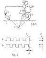
- FIG 5 shows a fifth embodiment of the invention Scattered smoke detector with an ellipsoid
- Figure 6 a amplitude modulated optical signal for determining a Distance
- Figure 7 amplitude modulated optical signals for identification of a cloud of smoke
- FIG. 8 of the scattered light smoke detector according to the invention with a Ultrasonic detection for foreign bodies.
- Scattered light smoke detectors used as fire detectors have the advantage of being independent of stray light sources, Dust, pollution, insects, short-term smoke and temporarily introduced foreign bodies in the measuring point, such as e.g. Cleaning equipment, to be.
- Longer term Smoke clouds as they arise in a fire, provide the scattered light smoke detector for a clear scatter signal, which is recognized as a fire detection signal, for example by comparison with a predetermined threshold. at a permanent retention of objects in the measuring point, this is the scattering point, is the scattered light smoke detector but functionally give a fire alarm.
- a scattered light smoke detector suggested that has means to smoke between to differentiate other foreign bodies.
- a processor relates to the time history analyzed by received signals of the light receiver.
- FIG. 1 shows a first embodiment of the invention scattered light smoke detector according to the invention as a block diagram shown.
- a cover 3 protects the Scattered light smoke detector against moisture, aggressive gases and mechanical damage.
- the cover 3 is as transparent plastic formed. Alternatively it is possible to use glass.
- the cover 3 is such procure them for the light for the Scattered light measurement is transparent. It can also be used as a Filter for unwanted interference act. Especially if infrared radiation is used, that is Ambient light easily through the cover 3 and the Light receiver 2 filterable.
- Behind the cover 3 is located on the one hand, a light transmitter 1, here a light emitting diode in Infrared.
- a laser preferably a semiconductor laser, and / or other wavelength ranges possible, which is controlled by a transmitter drive 5.
- the transmitter drive 5 is thus a driver circuit for the light transmitter 1. In the case of a laser, it is a typical laser driver circuit with temperature and Bias compensation.
- the control 5 is via a second output connected to a processor 7. Of the Processor 7 is via a data input / output with a Memory 8 connected in the permanently stored Reference signals are stored and the storage of intermediate values is used.
- About a second Data input is the processor 7 with a Reception evaluation 6 connected.
- About a data output is the processor 7 to a signaling device. 9 connected.
- An input of the reception evaluation 6 is with a light receiver 2 connected.
- the light receiver 2 is here a photodiode.
- the light emitting diode 1 and the photodiode 2 are arranged such that a scattering point 4 outside the Outdoor scattered light smoke detector is located.
- the reception evaluation 6 is here a receiver amplifier and an analog / digital conversion.
- the signaling device 9 may have a Be a light, a siren or a communication module, the signaling to a center, preferably via a bus transfers. This is particularly advantageous if several scattered light smoke detectors are used, the Connected to the central office via the bus central monitoring of a building.
- the processor 7 now performs a time course analysis of Receiving signals of the photodiode 2 by. There is smoke in the door Scattering point 4, this leads to a continuous Increase in the intensity of the received scattered light by the Photodiode 2. However, a foreign body in the scattering point 4th introduced, then when introducing the foreign body in the scattering point 4 a jump in the time course of Intensity function of the received signals by the Photodiode 2 take place, then after the introduction and the Remain the foreign body in the scattering point 4 again to cause a flat signal plateau. A short appearance a foreign body in the scattering point 4 calls a short Pulse in the reception function of the leakage signals and is thus recognized as a signal that is not for Alarm triggering is used.
- FIG. 2 shows a second embodiment of the invention represented scattered light smoke detector according to the invention, wherein around the light receiver 2 a facet mirror of two concave mirrors (concave mirror segments) 10 and 11 attached is.
- the concave mirrors 10 and 11 collect light from one Each time around its own scatter point and couple it in the light receiver 2 a.
- the scattering point (s) are Strictly speaking, areas of volume where the light lobe of the Radiation source and the receiving lobe of the light receiver to cut.
- two scatter points as it is for the optical axes of the two mirrors 10 and 11 and the optical axis of the light emitter 1 each two Intersections are.
- the light receiver 2 is therefore sensitive all around, so that the light receiver 2 now consists of several diodes, the light can receive from different directions, is composed.
- the cover 3 in turn protects the Scattered smoke detector from external attacks.
- the light receiver 2 is connected via its output to the Receive evaluation 6 connected via their data output is connected to the processor 7.
- the processor 7 is connected to the memory 8 via a data input / output. About a data output, the processor 7 with the Signaling device 9 connected.
- To a second Data input of the processor 7 is the transmitter drive 5 connected.
- a second output of the transmitter control 5 leads to the light emitter 1, here again a light emitting diode is. Furthermore, a laser can be used here.
- the concave mirrors 10 and 11 as Facet mirror is the integral of the captured Scattering areas formed by the light receiver 2.
- Presence of smoke is assumed to be all Scattering essentially homogeneous with the corresponding Smoke density provide a proportion of the scattered light signal, while a spider only locally sends a sub signal to the Receiver scatters.
- a spider as a foreign body of smoke be differentiated.
- the evaluation can in particular also done by an evaluation of the time signal.
- Smoke gives a continuous signal, while an insect as an example for a foreign body a signal jump when leaving and Entering each segment generates. An insect would accordingly a pulse train passing through the scattering area produce.
- a threshold value in the memory 8 is then provide, which sets a threshold for the amplitude from the smoke is recognized as recognized.
- a spider would be a signal result, which is below the threshold.
- the threshold is determined by experimental data.
- FIG. 3 shows a third embodiment of the invention Sreulichtrauchmelders invention shown.
- the Cover 3 again protects the scattered light smoke detector external attacks.
- the light transmitter 1 is above its entrance connected to the transmitter control 5.
- the transmitter control 5 is via a second output to the processor. 7 connected.
- the processor 7 is via a data input / output connected to the memory 8.
- To a second data input of the processor 7 is a photoreceptor array evaluation 13 connected.
- To a data output of the processor 7 is a signaling device 9 connected.
- the Photoreceptor array evaluation 13 is via its input with a photoreceiver array 12 connected.
- the photoreceiver array 12 consists of a field of photodiodes.
- a lens 14 is between the cover 3 and the photoreceptor array 12th arranged.
- the lens 14 is arranged such that the Photodiodes of the photoreceiver array 12 multiple locations to detect the scattering point 4.
- the photoreceiver array evaluation 13 asks the individual Signals from the photodiodes and digitized them to them then to the processor 7, which is a Spatial resolution of the received signals around the scattering point 4 performs.
- the processor 7 which is a Spatial resolution of the received signals around the scattering point 4 performs.
- the lens 14 a spatial distribution of To record signals.
- Through the beams 15, 16, 17 and 18 are exemplary two local areas, which by the Photoreceiver diode array 12 are detected, shown. Through this spatial resolution can now be clearly between Smoke that will be homogeneous, small animals that only in single areas emerge, and objects differ.
- FIG. 4 shows a fourth embodiment of the invention represented scattered light smoke detector according to the invention.
- the Cover 3 in turn protects the scattered light smoke detector external interventions.
- the light transmitter 1 is over its Input connected to an amplitude modulator 19.
- One Data output of the amplitude modulator 19 leads to a first data input of the processor 7.
- the transmitter control 5 is connected to a data input of the amplitude modulator 19 connected.
- a second output of the transmitter control 5 leads to a second data input of the processor 7.
- the Processor 7 is via its third data input with the Receiver evaluation 6 connected. Via a data input / output the processor 7 is connected to the memory 8.
- About a data output of the processor 7 is the Signaling device 9 connected.
- To an entrance the receiver evaluation 6 is the light receiver. 2 connected.
- the light emitter 1 and the light receiver 2 are arranged so that the scattering point 4 outside the Outdoor scattered light smoke detector is located.
- the amplitude modulator 19 forms from the electrical signal the transmitter driver 5 a pulse train and thereby performs an amplitude modulation. In the simplest form is this is just a switch, so a series of periodic light pulses in the light transmitter 1 is generated and then again a blanking is performed and this alternately in a clock, the amplitude modulator 19th pretends.
- the processor 7 evaluates the received signals in Comparison to these sent signals, the Amplitude modulator 19 transmits directly to the processor 7, by. As a result, the processor 7 is able, on the one hand a distance determination based on the phase shift between the transmitted and the received pulses perform and on the other hand check if it is a cloud of smoke or an object.
- FIG. 6 shows how pulse sequences, the were sent and received in phase differ.
- Figure 6a is the transmitted pulse train represented by the arrow 21, on the Reflection plane 22 falls.
- Figure 6b is the received Pulse sequence shown.
- the phase shift 23 is a measure of the Distance from the light transmitter and receiver to the Reflection plane 22.
- Figure 7a is again sent Pulse sequence shown that hits a cloud of smoke 25.
- the received pulse sequence is from the Cloud of smoke 25 shown. Because of that many scattering centers present in the cloud of smoke 25, the pulses widen the transmitted pulse train A, and it comes to a Pulse dispersion as shown in Figure 7b.
- the width of the received pulses in Figure 7b is a measure of whether smoke present or not. This can be done by means of a Threshold comparison can be determined by the processor 7. This threshold is then specified and in memory 8 stored.
- a Tunable wavelength light source as a light emitter 1. It can, for example, a tunable Semiconductor laser can be used in the infrared range, the tuned over a predetermined wavelength range will be to detect if the scattered light signals are dependent on the wavelength. This scattering will Called Rayleigh scattering. For small particles, as in a cloud of smoke, this is Rayleigh scattering wavelength dependent.
- the processor 7 is thus on the Transmitter control 5 on the currently used wavelength informed, then the received signals as a function of To analyze transmission wavelength.
- FIG. 5 shows a fifth embodiment of the invention represented scattered light smoke detector according to the invention.
- the Cover 3 again protects the scattered light smoke detector external interventions.
- the light transmitter 1 is over its Input connected to the transmitter drive 5, wherein the Transmitter control 5 via a data output with a first Data input of the processor 7 is connected.
- the processor 7 is via a data input / output with the memory 8 connected.
- a second data input is the processor 7 connected to the reception evaluation 6.
- At one Data output of the processor 7 is the Signaling device 9 connected.
- Of the Light receiver 2 is connected to an input of Receiver evaluation 6 connected.
- To the light receiver 2 is a Ellepsoid 20 arranged, which ensures that as much stray light in the light receiver. 2 is coupled. This improves the signal-to-noise ratio the scattered light smoke detector.
- An alternative method is that a stronger light emitter 1 is used.
- Fig. 8 the scattered light smoke detector according to the invention with an ultrasonic detection shown.
- the light transmitter 1 and the light receiver 2 are arranged so that the Scattering point 4 outside the scattered light smoke detector outdoors lies.
- the cover 3 protects the scattered light smoke detector external attacks.
- To an input of the light emitter 1 is the transmitter control 5 connected.
- a data output of the Transmitter drive 5 leads to a first data input of the Processor 7.
- the Ultrasonic receiver is aligned to the scattering point 4, on which an ultrasonic transmitter 26 is aligned.
- Of the Ultrasonic transmitter is either in continuous operation or in operated periodic periods.
- the Reception evaluation 6 To a third input of the processor 7 is the Reception evaluation 6 connected. To a data output of the processor 7 is a signaling 9 connected. Via a data input, the processor 7 is connected to the Memory 8 connected. To an entrance of the Reception evaluation 6, the light receiver 2 is connected.
- the processor. 7 based on the received signal from the signal processing 28, the received signals from the ultrasonic receiver 27th amplified and digitized, realizes that this is a Foreign body is and not smoke, which is the Scatter signals that the light receiver 2 receives causes.
- the optical signal received by the Supervised ultrasonic signal It is about Smoke that causes the scattering signals in the scattering point 4, then the ultrasonic receiver does not receive a received signal.
- Ultrasonic waves offer the option of targeting an area to sound so that false signals are unlikely.
- the function of an ultrasonic transmitter and receiver can also be integrated in one component. It will be first Ultrasound pulse emitted. Then you put on reception and waits for any of these Subject reflected signal (echo mode).
Landscapes
- Physics & Mathematics (AREA)
- General Physics & Mathematics (AREA)
- Engineering & Computer Science (AREA)
- Computer Security & Cryptography (AREA)
- Business, Economics & Management (AREA)
- Emergency Management (AREA)
- Chemical & Material Sciences (AREA)
- Analytical Chemistry (AREA)
- Multimedia (AREA)
- Fire-Detection Mechanisms (AREA)
- Investigating Or Analysing Materials By Optical Means (AREA)
Claims (9)
- Détecteur de fumée à lumière dispersée, comportant un photoémetteur (1) et un photorécepteur (2) installés de façon que le point de dispersion (4) du photoémetteur (1) et du photorécepteur (2) se situe à l'extérieur du détecteur de fumée à lumière dispersée, dans l'espace libre,
caractérisé par
un moyen de recouvrement (3) pour protéger le photoémetteur et le photorécepteur (2), ainsi que des moyens (7) pour distinguer entre la fumée et d'autres corps étrangers qui pourraient se trouver dans la zone entourant le point de dispersion (4),
les moyens pour distinguer entre la fumée et d'autres corps étrangers comprenant un processeur (7) pour analyser l'évolution chronologique des signaux de réception du photorécepteur (2), le processeur (7) étant relié au photorécepteur (2). - Détecteur de fumée à lumière dispersée selon la revendication 1,
caractérisé en ce que
les moyens pour distinguer entre la fumée et d'autres corps étrangers comprennent sur le photorécepteur (2), une optique (10, 11) qui injecte les signaux dispersés provenant de plusieurs zones de dispersion dans un domaine autour du point de dispersion (4) dans les photorécepteurs (2). - Détecteur de fumée à lumière dispersée selon la revendication 2,
caractérisé en ce que
l'optique est réalisée sous la forme d'un miroir à facettes (10, 11). - Détecteur de fumée à lumière dispersée selon les revendications 1, 2 ou 3,
caractérise en ce que
le photorécepteur est réalisé par un réseau de photorécepteurs (12), ce réseau de photorécepteurs (12) ayant au moins deux éléments photorécepteurs. - Détecteur de fumée à lumière dispersée selon la revendication 4,
caractérisé en ce qu'
un système de lentille (14) est installé en amont du réseau photorécepteur (12). - Détecteur de fumée à lumière dispersée selon les revendications 1, 2, 3, 4 ou 5,
caractérisé en ce que
le photoémetteur (1) est réalisé sous la forme d'une source lumineuse qui peut être accordée, et cette source lumineuse accordable émet la lumière avec une longueur d'onde variable en fonction des signaux de dispersion venant d'une commande d'émetteur (5). - Détecteur de fumée à lumière dispersée selon l'une des revendications 1 à 6,
caractérisé en ce que
le photoémetteur (1) peut être relié à un modulateur d'amplitude (19). - Détecteur de fumée à lumière dispersée selon l'une des revendications 1 à 6,
caractérisé en ce que
le détecteur de fumée à lumière dispersée comporte un capteur à ultrasons ayant un émetteur d'ultrasons et un récepteur d'ultrasons, et est installé pour surveiller le domaine autour du point de dispersion (4). - Détecteur de fumée à lumière dispersée selon la revendication 8,
caractérisé en ce que
le capteur d'ultrasons fonctionne en mode Echo.
Applications Claiming Priority (2)
| Application Number | Priority Date | Filing Date | Title |
|---|---|---|---|
| DE10046992A DE10046992C1 (de) | 2000-09-22 | 2000-09-22 | Streulichtrauchmelder |
| DE10046992 | 2000-09-22 |
Publications (3)
| Publication Number | Publication Date |
|---|---|
| EP1191496A1 EP1191496A1 (fr) | 2002-03-27 |
| EP1191496B1 true EP1191496B1 (fr) | 2004-08-11 |
| EP1191496B2 EP1191496B2 (fr) | 2010-11-24 |
Family
ID=7657231
Family Applications (1)
| Application Number | Title | Priority Date | Filing Date |
|---|---|---|---|
| EP01122157A Expired - Lifetime EP1191496B2 (fr) | 2000-09-22 | 2001-09-15 | Détecteur de fumée à lumière dispersée |
Country Status (6)
| Country | Link |
|---|---|
| US (1) | US6515589B2 (fr) |
| EP (1) | EP1191496B2 (fr) |
| AT (1) | ATE273545T1 (fr) |
| DE (3) | DE10046992C1 (fr) |
| ES (1) | ES2225374T5 (fr) |
| TR (1) | TR200402201T4 (fr) |
Cited By (1)
| Publication number | Priority date | Publication date | Assignee | Title |
|---|---|---|---|---|
| WO2012167858A1 (fr) | 2011-06-09 | 2012-12-13 | Ista International Gmbh | Détecteur de fumées et son procédé de fonctionnement |
Families Citing this family (59)
| Publication number | Priority date | Publication date | Assignee | Title |
|---|---|---|---|---|
| US6876305B2 (en) * | 1999-12-08 | 2005-04-05 | Gentex Corporation | Compact particle sensor |
| DE10232878B4 (de) * | 2002-07-19 | 2012-02-23 | Robert Bosch Gmbh | Vorrichtung und Verfahren zur Distanzmessung |
| DE10246056A1 (de) * | 2002-10-02 | 2004-04-22 | Robert Bosch Gmbh | Rauchmelder |
| AU2003902319A0 (en) | 2003-05-14 | 2003-05-29 | Garrett Thermal Systems Limited | Laser video detector |
| AU2004290246B2 (en) * | 2003-11-17 | 2010-06-10 | Hochiki Corporation | Smoke sensor using scattering light |
| DE102004001699A1 (de) | 2004-01-13 | 2005-08-04 | Robert Bosch Gmbh | Brandmelder |
| DE102004002591B4 (de) | 2004-01-16 | 2016-03-03 | Robert Bosch Gmbh | Brandmelder |
| CA2883638C (fr) * | 2004-11-12 | 2017-06-20 | Xtralis Technologies Ltd | Detecteur de particules, systeme et procede |
| DE102005045484A1 (de) | 2005-07-29 | 2007-02-01 | Cedes Ag | Sensorvorrichtung |
| EP1783713B1 (fr) * | 2005-11-04 | 2008-05-28 | Siemens Aktiengesellschaft | Prévention contre la manipulation abusive d'un détecteur de feu |
| EP1783712B1 (fr) * | 2005-11-04 | 2008-05-07 | Siemens Aktiengesellschaft | Détecteur de feu optique fonctionnant par principe d'absorbance et diffusion combinée |
| DE102006023048C5 (de) * | 2006-05-17 | 2014-12-11 | Techem Energy Services Gmbh | Brandwarnmelder und Verfahren zur Überprüfung dessen Funktionsfähigkeit |
| DE202006015553U1 (de) | 2006-10-09 | 2006-12-14 | Schako Klima Luft Ferdinand Schad Kg Zweigniederlassung Kolbingen | Vorrichtung zur Erkennung von Rauch |
| DE102007013295A1 (de) | 2007-03-16 | 2008-09-18 | Aoa Apparatebau Gauting Gmbh | Rauchmelder |
| US7493816B1 (en) * | 2007-09-28 | 2009-02-24 | Honeywell International Inc. | Smoke detectors |
| ATE459949T1 (de) * | 2007-09-28 | 2010-03-15 | Siemens Building Tech Ag | Vorrichtung zur überwachung eines brandmelders und konfigurierungsverfahren und brandmelder |
| CN101836244B (zh) * | 2007-10-26 | 2012-05-23 | 松下电器产业株式会社 | 火灾警报系统 |
| CA2993208C (fr) | 2007-11-15 | 2021-01-26 | Garrett Thermal Systems Limited | Detection de particules |
| US7760359B2 (en) * | 2007-12-10 | 2010-07-20 | Honeywell International Inc. | Beam detector distance measurement |
| DK2093734T3 (da) | 2008-02-19 | 2011-10-10 | Siemens Ag | Røgalarm med tidslig fortolkning af et tilbagekoblingssignal, testfremgangsmåde til funktionsdygtighed af en røgalarm |
| CN102171733B (zh) * | 2008-10-09 | 2015-04-29 | 报知机株式会社 | 烟检测器 |
| EP2189956B1 (fr) | 2008-11-21 | 2013-05-08 | Hekatron Vertriebs GmbH | Détecteur d'incendie et procédé destiné à la reconnaissance d'impuretés |
| DE102009013556A1 (de) | 2009-03-17 | 2010-09-30 | Airbus Deutschland Gmbh | Streulichtrauchmelder |
| US8638436B2 (en) * | 2009-09-15 | 2014-01-28 | Hochiki Corporation | Smoke sensor |
| WO2011057997A2 (fr) * | 2009-11-16 | 2011-05-19 | Thomson Licensing | Procede d'estimation de diffusion de la lumiere |
| DE102009047531A1 (de) * | 2009-12-04 | 2011-06-09 | Atral- Secal Gmbh | Rauchmelder mit Ultraschall-Abdecküberwachung |
| EP2423895B1 (fr) | 2010-08-26 | 2017-03-08 | Siemens Schweiz AG | Alarme incendie à lumière diffusée dotée de moyens de suppression d'une alerte acoustique en cas de faible tension d'alimentation |
| DE102010037744B3 (de) * | 2010-09-23 | 2011-12-08 | Sick Ag | Optoelektronischer Sensor |
| US8624745B2 (en) | 2011-03-16 | 2014-01-07 | Honeywell International Inc. | High sensitivity and high false alarm immunity optical smoke detector |
| DE102011108390B4 (de) | 2011-07-22 | 2019-07-11 | PPP "KB Pribor" Ltd. | Verfahren zur Herstellung eines Rauchdetektors vom offenen Typ |
| DE102011108389A1 (de) | 2011-07-22 | 2013-01-24 | PPP "KB Pribor" Ltd. | Rauchdetektor |
| DE102012201589A1 (de) | 2012-02-03 | 2013-08-08 | Robert Bosch Gmbh | Brandmelder mit Mensch-Maschinen-Schnittstelle sowie Verfahren zur Steuerung des Brandmelders |
| US9191762B1 (en) | 2012-02-23 | 2015-11-17 | Joseph M. Matesa | Alarm detection device and method |
| US8907802B2 (en) | 2012-04-29 | 2014-12-09 | Valor Fire Safety, Llc | Smoke detector with external sampling volume and ambient light rejection |
| US8952821B2 (en) | 2012-04-29 | 2015-02-10 | Valor Fire Safety, Llc | Smoke detector utilizing ambient-light sensor, external sampling volume, and internally reflected light |
| US9140646B2 (en) | 2012-04-29 | 2015-09-22 | Valor Fire Safety, Llc | Smoke detector with external sampling volume using two different wavelengths and ambient light detection for measurement correction |
| ES2529124T3 (es) | 2012-09-07 | 2015-02-17 | Amrona Ag | Dispositivo y procedimiento para la detección de señales de luz dispersada |
| DE102013101280B4 (de) | 2013-02-08 | 2025-02-20 | Schako Kg | Rauchmelder |
| DE202013005222U1 (de) | 2013-06-08 | 2013-07-01 | Manuel Müller | Deckenlampe mit Rauchmelder |
| KR20160079057A (ko) | 2013-10-30 | 2016-07-05 | 발로르 파이어 세이프티, 엘엘씨 | 외부 샘플링 볼륨 및 주변광 배제를 갖는 연기 감지기 |
| EP2879104B2 (fr) | 2013-11-27 | 2022-05-11 | Siemens Schweiz AG | Dispositif auxiliaire pour un détecteur de danger configuré sous forme de détecteur ponctuel pour la surveillance du fonctionnement du détecteur de danger, agencement et utilisation d'un tel dispositif |
| DE102014200243B4 (de) | 2014-01-09 | 2025-10-30 | Robert Bosch Gmbh | Rauchmelder mit Umgebungslichterkennung sowie Verfahren |
| US9652958B2 (en) | 2014-06-19 | 2017-05-16 | Carrier Corporation | Chamber-less smoke sensor |
| EP3029647B1 (fr) | 2014-12-04 | 2017-05-31 | Siemens Schweiz AG | Détecteur de fumée à écran diffusant ouvert, notamment équipé d'une LED Side-looker |
| GB2537940B (en) * | 2015-05-01 | 2018-02-14 | Thorn Security | Fire detector drift compensation |
| EP3091516A1 (fr) | 2015-05-06 | 2016-11-09 | Siemens Schweiz AG | Détecteur de fumée à écran diffusant ouvert et appareil de communication mobile pour un tel détecteur de fumée à écran diffusant ouvert pour la réception de données de détecteur et pour l'envoi des données mises à jour |
| EP3091517B1 (fr) * | 2015-05-06 | 2017-06-28 | Siemens Schweiz AG | Détecteur de fumée à écran diffusant ouvert et appareil de contrôle pour un tel détecteur de fumée à écran diffusant ouvert |
| WO2018027104A1 (fr) | 2016-08-04 | 2018-02-08 | Carrier Corporation | Détecteur de fumée |
| ES2897220T3 (es) * | 2017-06-05 | 2022-02-28 | Carrier Corp | Método para monitorizar el estado de la cubierta protectora de un dispositivo de detección |
| WO2018226567A1 (fr) | 2017-06-09 | 2018-12-13 | Carrier Corporation | Détecteur de fumée sans chambre avec détection et surveillance de la qualité de l'air intérieur |
| EP3454311B1 (fr) | 2017-09-08 | 2020-06-10 | Tyco Fire & Security GmbH | Détecteur de fumée sans chambre |
| US20190293556A1 (en) | 2018-03-26 | 2019-09-26 | Kidde Technologies, Inc. | Protective cover for chamberless point sensor |
| US11176796B2 (en) | 2018-07-13 | 2021-11-16 | Carrier Corporation | High sensitivity fiber optic based detection |
| US11948439B2 (en) | 2018-07-13 | 2024-04-02 | Carrier Corporation | High sensitivity fiber optic based detection |
| WO2020014461A2 (fr) | 2018-07-13 | 2020-01-16 | Carrier Corporation | Robustesse améliorée pour la détection de fumée par fibre optique à haute sensibilité |
| DE102018216836B3 (de) * | 2018-10-01 | 2020-02-13 | Siemens Schweiz Ag | Offener Streulichtrauchmelder mit koaxialer Anordnung von Lichtsender und Lichtempfänger |
| WO2020118001A1 (fr) * | 2018-12-05 | 2020-06-11 | Carrier Corporation | Détection d'incendie à transmission de données |
| CN113470301A (zh) * | 2021-07-29 | 2021-10-01 | 上海嘉筠通信技术有限公司 | 一种带自动灭火材料的烟雾报警器 |
| DE102023203881A1 (de) | 2023-04-26 | 2024-10-31 | Hekatron Vertriebs Gmbh | Brandmelder und Vorrichtung zur Überwachung |
Family Cites Families (12)
| Publication number | Priority date | Publication date | Assignee | Title |
|---|---|---|---|---|
| US4206456A (en) * | 1975-06-23 | 1980-06-03 | Chloride Incorporated | Smoke detector |
| JP2935549B2 (ja) * | 1990-08-23 | 1999-08-16 | 能美防災株式会社 | 火災検出方法及び装置 |
| US5502434A (en) * | 1992-05-29 | 1996-03-26 | Hockiki Kabushiki Kaisha | Smoke sensor |
| US5420567A (en) * | 1993-02-02 | 1995-05-30 | Schwarz; Frank | Combination fire/intrusion alarm detectors using active infared elements |
| CH686914A5 (de) * | 1993-12-20 | 1996-07-31 | Cerberus Ag | Brandmeldesystem zur Frueherkennung von Braenden. |
| DE4414166C1 (de) * | 1994-04-22 | 1995-12-07 | Lorenz Mesgeraetebau | Verfahren und Vorrichtung zur Messung der Lichtstreuung an Partikeln |
| JPH1123458A (ja) * | 1997-05-08 | 1999-01-29 | Nittan Co Ltd | 煙感知器および監視制御システム |
| US6150935A (en) * | 1997-05-09 | 2000-11-21 | Pittway Corporation | Fire alarm system with discrimination between smoke and non-smoke phenomena |
| DE19835797C2 (de) * | 1998-08-07 | 2003-01-23 | Deutsch Zentr Luft & Raumfahrt | Verfahren zur Erfassung von Rauch mittels eines Lidar-Systems |
| DE19912911C2 (de) * | 1999-03-22 | 2001-07-19 | Schako Metallwarenfabrik | Vorrichtung zur Erkennung von Rauch |
| DE19951403B4 (de) † | 1999-10-26 | 2010-01-07 | Schako Metallwarenfabrik Ferdinand Schad Kg Zweigniederlassung Kolbingen | Verfahren zur Erkennung von Rauch |
| EP1039426A3 (fr) * | 1999-03-22 | 2001-01-31 | Schako Metallwarenfabrik Ferdinand Schad Kg | Dispositif pour détecter de la fumée |
-
2000
- 2000-09-22 DE DE10046992A patent/DE10046992C1/de not_active Expired - Lifetime
- 2000-09-22 DE DE10066246A patent/DE10066246A1/de not_active Withdrawn
-
2001
- 2001-09-15 AT AT01122157T patent/ATE273545T1/de active
- 2001-09-15 TR TR2004/02201T patent/TR200402201T4/xx unknown
- 2001-09-15 EP EP01122157A patent/EP1191496B2/fr not_active Expired - Lifetime
- 2001-09-15 ES ES01122157T patent/ES2225374T5/es not_active Expired - Lifetime
- 2001-09-15 DE DE50103194T patent/DE50103194D1/de not_active Expired - Lifetime
- 2001-09-21 US US09/960,019 patent/US6515589B2/en not_active Expired - Lifetime
Cited By (1)
| Publication number | Priority date | Publication date | Assignee | Title |
|---|---|---|---|---|
| WO2012167858A1 (fr) | 2011-06-09 | 2012-12-13 | Ista International Gmbh | Détecteur de fumées et son procédé de fonctionnement |
Also Published As
| Publication number | Publication date |
|---|---|
| ATE273545T1 (de) | 2004-08-15 |
| TR200402201T4 (tr) | 2004-10-21 |
| DE10066246A1 (de) | 2005-10-06 |
| ES2225374T3 (es) | 2005-03-16 |
| DE50103194D1 (de) | 2004-09-16 |
| US6515589B2 (en) | 2003-02-04 |
| EP1191496A1 (fr) | 2002-03-27 |
| ES2225374T5 (es) | 2011-04-08 |
| US20020080040A1 (en) | 2002-06-27 |
| DE10046992C1 (de) | 2002-06-06 |
| EP1191496B2 (fr) | 2010-11-24 |
Similar Documents
| Publication | Publication Date | Title |
|---|---|---|
| EP1191496B1 (fr) | Détecteur de fumée à lumière dispersée | |
| EP2093733B1 (fr) | Détection de fumée à l'aide de deux mesures à lumière diffusée spectrales différentes | |
| EP2093734B1 (fr) | Détecteur de fumée doté d'une évaluation temporelle d'un signal de rétrodiffusion, procédé de test pour la capacité fonctionnelle d'un détecteur de fumée | |
| DE10011411C2 (de) | Bildgebender Brandmelder | |
| EP3029647B1 (fr) | Détecteur de fumée à écran diffusant ouvert, notamment équipé d'une LED Side-looker | |
| EP2252984B1 (fr) | Évaluation d'un signal différentiel entre deux signaux de sortie de deux dispositifs de réception situés dans un dispositif de détection | |
| EP2541273B1 (fr) | Détection et détermination de distance d'objets | |
| EP2899565B1 (fr) | Capteur mesurant l'éloignement et procédé destiné à la détection et la détermination de l'éloignement d'objets | |
| EP1376504B1 (fr) | Capteur de fumée par diffusion de lumière | |
| EP0756703B1 (fr) | Dispositif de mesure de la dispersion de la lumiere par des particules | |
| EP3270362B1 (fr) | Détecteur d'incendie comprenant une chambre de mesure et un support de circuit destiné à disposer ensemble un détecteur d'incendie de la chambre de mesure et au moins un autre capteur destiné à détecter une grandeur de mesure dans l'environnement à l'extérieur du détecteur d'incendie | |
| DE4341080C1 (de) | Lichtelektrische Vorrichtung mit einem Testobjekt | |
| WO2004001694A1 (fr) | Detecteur d'incendie | |
| WO2004032083A1 (fr) | Detecteur de fumees | |
| EP1012805A1 (fr) | Detecteur de fumee | |
| DE3930272C2 (fr) | ||
| EP2093731A1 (fr) | Détecteur de fumée optique linéaire doté de plusieurs rayons partiels | |
| DE102005010657B4 (de) | Objekterfassungsvorrichtung | |
| DE19900019A1 (de) | Faseroptischer Sensor | |
| DE202007008540U1 (de) | Optischer Sensor zum Nachweis von Objekten im Bereich einer sicherheitsmäßig zu überwachenden Einrichtung | |
| DE19958358B4 (de) | Meß- und Zählsensor | |
| DE19814575A1 (de) | Optischer Sensor | |
| DE10004570A1 (de) | Optisches Sensorsystem zur kontinuierlichen Analyse von flüssigen oder gasförmigen Medien | |
| DE10003691A1 (de) | Optischer Sensor | |
| EP1818884A1 (fr) | Dispositif de détection de fumée |
Legal Events
| Date | Code | Title | Description |
|---|---|---|---|
| PUAI | Public reference made under article 153(3) epc to a published international application that has entered the european phase |
Free format text: ORIGINAL CODE: 0009012 |
|
| AK | Designated contracting states |
Kind code of ref document: A1 Designated state(s): AT BE CH CY DE DK ES FI FR GB GR IE IT LI LU MC NL PT SE TR |
|
| AX | Request for extension of the european patent |
Free format text: AL;LT;LV;MK;RO;SI |
|
| 17P | Request for examination filed |
Effective date: 20020927 |
|
| AKX | Designation fees paid |
Free format text: AT BE CH CY DE DK ES FI FR GB GR IE IT LI LU MC NL PT SE TR |
|
| 17Q | First examination report despatched |
Effective date: 20030611 |
|
| GRAP | Despatch of communication of intention to grant a patent |
Free format text: ORIGINAL CODE: EPIDOSNIGR1 |
|
| GRAS | Grant fee paid |
Free format text: ORIGINAL CODE: EPIDOSNIGR3 |
|
| GRAA | (expected) grant |
Free format text: ORIGINAL CODE: 0009210 |
|
| AK | Designated contracting states |
Kind code of ref document: B1 Designated state(s): AT BE CH CY DE DK ES FI FR GB GR IE IT LI LU MC NL PT SE TR |
|
| PG25 | Lapsed in a contracting state [announced via postgrant information from national office to epo] |
Ref country code: NL Free format text: LAPSE BECAUSE OF FAILURE TO SUBMIT A TRANSLATION OF THE DESCRIPTION OR TO PAY THE FEE WITHIN THE PRESCRIBED TIME-LIMIT Effective date: 20040811 Ref country code: IE Free format text: LAPSE BECAUSE OF FAILURE TO SUBMIT A TRANSLATION OF THE DESCRIPTION OR TO PAY THE FEE WITHIN THE PRESCRIBED TIME-LIMIT Effective date: 20040811 Ref country code: FI Free format text: LAPSE BECAUSE OF FAILURE TO SUBMIT A TRANSLATION OF THE DESCRIPTION OR TO PAY THE FEE WITHIN THE PRESCRIBED TIME-LIMIT Effective date: 20040811 Ref country code: CY Free format text: LAPSE BECAUSE OF FAILURE TO SUBMIT A TRANSLATION OF THE DESCRIPTION OR TO PAY THE FEE WITHIN THE PRESCRIBED TIME-LIMIT Effective date: 20040811 |
|
| REG | Reference to a national code |
Ref country code: GB Ref legal event code: FG4D Free format text: NOT ENGLISH |
|
| REG | Reference to a national code |
Ref country code: CH Ref legal event code: EP |
|
| REG | Reference to a national code |
Ref country code: CH Ref legal event code: NV Representative=s name: SCINTILLA AG, DIREKTION |
|
| REG | Reference to a national code |
Ref country code: IE Ref legal event code: FG4D Free format text: GERMAN |
|
| PG25 | Lapsed in a contracting state [announced via postgrant information from national office to epo] |
Ref country code: LU Free format text: LAPSE BECAUSE OF NON-PAYMENT OF DUE FEES Effective date: 20040915 |
|
| REF | Corresponds to: |
Ref document number: 50103194 Country of ref document: DE Date of ref document: 20040916 Kind code of ref document: P |
|
| PG25 | Lapsed in a contracting state [announced via postgrant information from national office to epo] |
Ref country code: MC Free format text: LAPSE BECAUSE OF NON-PAYMENT OF DUE FEES Effective date: 20040930 Ref country code: BE Free format text: LAPSE BECAUSE OF NON-PAYMENT OF DUE FEES Effective date: 20040930 |
|
| PG25 | Lapsed in a contracting state [announced via postgrant information from national office to epo] |
Ref country code: SE Free format text: LAPSE BECAUSE OF FAILURE TO SUBMIT A TRANSLATION OF THE DESCRIPTION OR TO PAY THE FEE WITHIN THE PRESCRIBED TIME-LIMIT Effective date: 20041111 Ref country code: GR Free format text: LAPSE BECAUSE OF FAILURE TO SUBMIT A TRANSLATION OF THE DESCRIPTION OR TO PAY THE FEE WITHIN THE PRESCRIBED TIME-LIMIT Effective date: 20041111 Ref country code: DK Free format text: LAPSE BECAUSE OF FAILURE TO SUBMIT A TRANSLATION OF THE DESCRIPTION OR TO PAY THE FEE WITHIN THE PRESCRIBED TIME-LIMIT Effective date: 20041111 |
|
| GBT | Gb: translation of ep patent filed (gb section 77(6)(a)/1977) |
Effective date: 20041215 |
|
| NLV1 | Nl: lapsed or annulled due to failure to fulfill the requirements of art. 29p and 29m of the patents act | ||
| REG | Reference to a national code |
Ref country code: ES Ref legal event code: FG2A Ref document number: 2225374 Country of ref document: ES Kind code of ref document: T3 |
|
| REG | Reference to a national code |
Ref country code: IE Ref legal event code: FD4D |
|
| BERE | Be: lapsed |
Owner name: ROBERT BOSCH G.M.B.H. Effective date: 20040930 |
|
| PLAQ | Examination of admissibility of opposition: information related to despatch of communication + time limit deleted |
Free format text: ORIGINAL CODE: EPIDOSDOPE2 |
|
| PLBQ | Unpublished change to opponent data |
Free format text: ORIGINAL CODE: EPIDOS OPPO |
|
| PLAQ | Examination of admissibility of opposition: information related to despatch of communication + time limit deleted |
Free format text: ORIGINAL CODE: EPIDOSDOPE2 |
|
| PLAR | Examination of admissibility of opposition: information related to receipt of reply deleted |
Free format text: ORIGINAL CODE: EPIDOSDOPE4 |
|
| PLBI | Opposition filed |
Free format text: ORIGINAL CODE: 0009260 |
|
| PLBQ | Unpublished change to opponent data |
Free format text: ORIGINAL CODE: EPIDOS OPPO |
|
| PLAX | Notice of opposition and request to file observation + time limit sent |
Free format text: ORIGINAL CODE: EPIDOSNOBS2 |
|
| ET | Fr: translation filed | ||
| 26 | Opposition filed |
Opponent name: NOVAR GMBH Effective date: 20050509 |
|
| PLAF | Information modified related to communication of a notice of opposition and request to file observations + time limit |
Free format text: ORIGINAL CODE: EPIDOSCOBS2 |
|
| PLBB | Reply of patent proprietor to notice(s) of opposition received |
Free format text: ORIGINAL CODE: EPIDOSNOBS3 |
|
| APBP | Date of receipt of notice of appeal recorded |
Free format text: ORIGINAL CODE: EPIDOSNNOA2O |
|
| APAH | Appeal reference modified |
Free format text: ORIGINAL CODE: EPIDOSCREFNO |
|
| APBQ | Date of receipt of statement of grounds of appeal recorded |
Free format text: ORIGINAL CODE: EPIDOSNNOA3O |
|
| BERE | Be: lapsed |
Owner name: ROBERT *BOSCH G.M.B.H. Effective date: 20040930 |
|
| PG25 | Lapsed in a contracting state [announced via postgrant information from national office to epo] |
Ref country code: PT Free format text: LAPSE BECAUSE OF NON-PAYMENT OF DUE FEES Effective date: 20050111 |
|
| PLAB | Opposition data, opponent's data or that of the opponent's representative modified |
Free format text: ORIGINAL CODE: 0009299OPPO |
|
| APBU | Appeal procedure closed |
Free format text: ORIGINAL CODE: EPIDOSNNOA9O |
|
| PUAH | Patent maintained in amended form |
Free format text: ORIGINAL CODE: 0009272 |
|
| STAA | Information on the status of an ep patent application or granted ep patent |
Free format text: STATUS: PATENT MAINTAINED AS AMENDED |
|
| 27A | Patent maintained in amended form |
Effective date: 20101124 |
|
| AK | Designated contracting states |
Kind code of ref document: B2 Designated state(s): AT BE CH CY DE DK ES FI FR GB GR IE IT LI LU MC NL PT SE TR |
|
| REG | Reference to a national code |
Ref country code: CH Ref legal event code: AEN Free format text: AUFRECHTERHALTUNG DES PATENTES IN GEAENDERTER FORM |
|
| REG | Reference to a national code |
Ref country code: ES Ref legal event code: DC2A Ref document number: 2225374 Country of ref document: ES Kind code of ref document: T5 Effective date: 20110408 |
|
| REG | Reference to a national code |
Ref country code: FR Ref legal event code: PLFP Year of fee payment: 16 |
|
| PGFP | Annual fee paid to national office [announced via postgrant information from national office to epo] |
Ref country code: AT Payment date: 20160921 Year of fee payment: 16 |
|
| PGFP | Annual fee paid to national office [announced via postgrant information from national office to epo] |
Ref country code: ES Payment date: 20160923 Year of fee payment: 16 |
|
| PGFP | Annual fee paid to national office [announced via postgrant information from national office to epo] |
Ref country code: IT Payment date: 20160922 Year of fee payment: 16 |
|
| REG | Reference to a national code |
Ref country code: FR Ref legal event code: PLFP Year of fee payment: 17 |
|
| REG | Reference to a national code |
Ref country code: AT Ref legal event code: MM01 Ref document number: 273545 Country of ref document: AT Kind code of ref document: T Effective date: 20170915 |
|
| PG25 | Lapsed in a contracting state [announced via postgrant information from national office to epo] |
Ref country code: IT Free format text: LAPSE BECAUSE OF NON-PAYMENT OF DUE FEES Effective date: 20170915 Ref country code: AT Free format text: LAPSE BECAUSE OF NON-PAYMENT OF DUE FEES Effective date: 20170915 |
|
| REG | Reference to a national code |
Ref country code: FR Ref legal event code: PLFP Year of fee payment: 18 |
|
| REG | Reference to a national code |
Ref country code: ES Ref legal event code: FD2A Effective date: 20181019 |
|
| PG25 | Lapsed in a contracting state [announced via postgrant information from national office to epo] |
Ref country code: ES Free format text: LAPSE BECAUSE OF NON-PAYMENT OF DUE FEES Effective date: 20170916 |
|
| PGFP | Annual fee paid to national office [announced via postgrant information from national office to epo] |
Ref country code: TR Payment date: 20200914 Year of fee payment: 20 Ref country code: FR Payment date: 20200921 Year of fee payment: 20 Ref country code: GB Payment date: 20200923 Year of fee payment: 20 |
|
| PGFP | Annual fee paid to national office [announced via postgrant information from national office to epo] |
Ref country code: CH Payment date: 20200925 Year of fee payment: 20 |
|
| PGFP | Annual fee paid to national office [announced via postgrant information from national office to epo] |
Ref country code: DE Payment date: 20201121 Year of fee payment: 20 |
|
| REG | Reference to a national code |
Ref country code: DE Ref legal event code: R071 Ref document number: 50103194 Country of ref document: DE |
|
| REG | Reference to a national code |
Ref country code: GB Ref legal event code: PE20 Expiry date: 20210914 |
|
| PG25 | Lapsed in a contracting state [announced via postgrant information from national office to epo] |
Ref country code: GB Free format text: LAPSE BECAUSE OF EXPIRATION OF PROTECTION Effective date: 20210914 |
|
| PG25 | Lapsed in a contracting state [announced via postgrant information from national office to epo] |
Ref country code: TR Free format text: LAPSE BECAUSE OF NON-PAYMENT OF DUE FEES Effective date: 20210915 |